Ultraheat - Heating TRUMA - Free user manual and instructions
Find the device manual for free Ultraheat TRUMA in PDF.

| Product Type | Electric auxiliary heater for motorhome |
| Brand | Truma |
| Model | Ultraheat |
| Weight | Approx. 2 kg |
| Power supply | 230 V~, 50 Hz |
| Available power levels | 500 W, 1000 W, 2000 W |
| Current consumption per level | 500 W: 2.2 A; 1000 W: 4.5 A; 2000 W: 8.5 A |
| Main function | Electric supplementary heater for Truma S 3004/S 5004 heaters |
| Power setting | 3-position rotary switch (500/1000/2000 W) + off |
| Temperature setting | Rotary knob from 1 to 9 |
| Operating indicator | Green LED lit when operating |
| Control type | Automatic with integrated temperature sensor in the control unit |
| Compatibility | Truma heaters S 3004, S 3004 P, S 5004, S 5004 E, S 5004 E NL (from 04/2012) |
| Prohibited use | Do not use with S models prior to 04/2012, nor outside the vehicle |
| Optional accessories | Extension cable 5 m (34300-01), external sensor FFC 2 (34203-01) |
| Maintenance and cleaning | No maintenance required (self-cleaning). Clean only when cold and disconnected from power |
| Repairs | Must be carried out exclusively by qualified Truma-approved personnel |
| Manufacturer warranty | 24 months in EU + Iceland, Norway, Switzerland, Turkey |
| Disposal | Observe national regulations (e.g., ELV directive in Germany) |
Frequently Asked Questions - Ultraheat TRUMA
User questions about Ultraheat TRUMA
0 question about this device. Answer the ones you know or ask your own.
Ask a new question about this device
Download the instructions for your Heating in PDF format for free! Find your manual Ultraheat - TRUMA and take your electronic device back in hand. On this page are published all the documents necessary for the use of your device. Ultraheat by TRUMA.
USER MANUAL Ultraheat TRUMA
natural_image
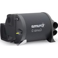
Exterior view of a modern electric heater unit (no visible text or symbols)EN Operating instructions
To be kept in the vehicle
FR Mode d'emploi
natural_image
3D mechanical component diagram showing a circular feature with a curved arrow indicating rotation (no text or symbols)Abb. 1
text_image
Technical diagram of a mechanical device with numbered components, likely a valve or connector assembly.Abb. 2
1 About these instructions 9
1.1 Document number 9
1.2 Validity 9
1.3 Designations 9
1.4 Target group 9
1.5 Supporting documents 9
1.6 Symbols and means of representation 9
1.7 Warnings 10
1.8 Abbreviations and glossary 10
2 Purpose 10
2.1 Intended use 10
2.2 Inappropriate use 10
2.3 Operating approval 10
2.4 Installation, dismantling, repositioning ..... 10
3 Safety instructions 10
3.1 General safety 10
3.2 Obligations of the operator / vehicle owner .. 11
3.3 Safe operation 11
3.4 Troubleshooting 12
4 Product Description 12
4.1 Design 12
4.2 Product labelling 12
4.3 Function 12
4.4 Operation 12
4.5 Control panel 13
4.6 Accessories* 13
5 Start-Up 13
6 Operation 13
6.1 Switching on Ultraheat 13
6.2 Switching off Ultraheat 13
7 Faults 13
8 Cleaning and Care 13
9 Repair 14
10 Disposal and Recycling 14
11 Technical Data 14
12 WARRANTY 14
12.1 Scope of Manufacturer's Warranty 14
12.2 Warranty exclusions 15
12.3 Making a warranty claim 15
1 About these instructions
These instructions are part of the product.
▶ Always carry the operating instructions in the vehicle.
▶ Also make the safety instructions available to other users.
1.1 Document number
The document number of these instructions can be found in the footer on every page and on the back page.
The document number consists of
• Part number (10 digits)
- Revision status (2 digits)
• Publication date (month/year)
1.2 Validity
These instructions are for the Ultraheat electric additional heater.
1.3 Designations
Collectively. Truma S heaters are described as S-heaters below
1.4 Target group
These instructions are intended for users.
For the sake of simplicity, in the following, no distinction is made between genders. Gender equality is intended in the way terms are used.
1.5 Supporting documents
Operating instructions for the heater in which the Ultraheat electric additional heater is installed.
1.6 Symbols and means of representation
| Symbol | Meaning |
| Warning about dangers to persons | |
| Expert | |
| Additional information to provide a better understanding or to optimise work processes. | |
| Symbol for an action.Something must be done here. | |
| * | Optional parts |
| (Fig. 3-1) | Reference to a picturee.g. Figure 3 - number 1 |
1.7 Warnings
In these instructions, warnings are used to warn about material damage and injury to persons.
▶Always read and observe warnings.
| Warning word Meaning | |
| DANGER | Danger for persons.Failure to observe will result in serious injury or death. |
| WARNING | Danger for persons.Failure to observe could result in serious injury or death. |
| CAUTION | Danger for persons.Failure to observe could result in minor injury. |
| NOTICE | Information to prevent material damage |
1.8 Abbreviations and glossary
| Word Meaning | |
| ESD | (englisch: Electro Static Device Electronic components that are sensitive to static charges. |
| LED | (englisch: Light Emitting Diode Light diode, indicator light |
| Line power | Power supplied to the vehicle from outside. A connection is usually established from a power supply socket at the campsite to the external socket on the vehicle using an extension cable. |
2 Purpose
2.1 Intended use
The Ultraheat electrical additional heater is an accessory for S-heaters and is approved solely for installation and operation in one of the following heaters:
• Truma S 3004, S 3004 P
• Truma S 5004, S 5004 E, S 5004 E NL
The intended use of the respective S-heater in accordance with regulations also applies.
2.2 Inappropriate use
All uses other than those listed under intended use are unauthorised and therefore not permitted.
The Ultraheat electric additional heater may not be used with the following heaters:
• All S-heaters manufactured before 04/2012
- Trumatic S 3002, S 3002 P
- Trumatic S 5002, S 5002 E, S 5002 E NL
• Trumatic S 2200, S 2200 P, Truma S 2200
- Trumatic S 55 T
• Trumatic S 3002 K, S 5002 K
Ultraheat electric additional heaters may not be operated separately outside an S-heater.
Ultraheat electric additional heaters may not be operated outdoors, in other words, not outside a vehicle.
2.3 Operating approval
The following circumstances invalidate the operating approval of the appliance:
- Modifications to the device, including accessories.
- Using replacement and accessory parts other than original Truma parts.
- Not observing the information in these operating instructions.
In some countries, these circumstances also invalidate the operating approval for the vehicle.
2.4 Installation, dismantling, repositioning
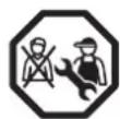
Only competent, trained personnel (experts) may install and repair the Truma product and carry out the function check with consideration of the installation and operating instructions and the current recognised
rules of engineering. Experts are persons who, based on their professional training, their knowledge of and experience with Truma products and the relevant standards, are able to carry out the required work properly and recognise potential hazards.
The following applies to non-experts:
▶Do not install the appliance, either in different locations or in different vehicles.
▶Do not dismantle the appliance, reposition it or repair it on your own.
▶Have the appliance installed, dismantled or repositioned only by an expert.
3 Safety instructions
3.1 General safety
Not following the rules in the operating instructions can result in serious material damage and serious risk to the health or life of persons.
Read and closely observe the safety instructions to prevent danger, material damage and injury.
Carefully read and observe the operating instructions for the appliance and supporting documents regarding the gas supply (gas tanks, gas lines) and the vehicle, and keep them in a safe place for later use.
Observe local laws, guidelines and standards associated with the use and operation of the appliance.
3.2 Obligations of the operator / vehicle owner
Equipment safety
▶Make sure that the appliance can be operated properly in all operating phases.
▶Check the heater and the gas system in accordance with the relevant national regulations and arrange for the prescribed inspection intervals.
Duty of supervision
The vehicle owner is responsible for correct operation of the appliance. Children aged under 3 years must be kept away unless they are under constant supervision. Children aged over 3 years and under 8 years may only switch the appliance on and off if they are under supervision or if they have been instructed on how to safely use the appliance and have understood the potential dangers, and provided that the appliance is located or installed in its normal place of use.
Children aged between 3 and 8 years old may not insert the plug into the socket, regulate the appliance, clean the appliance and/or perform user maintenance. This appliance may be used by children from 8 years old and by persons with reduced physical, sensory or mental capabilities or with a lack of experience and knowledge only if they are supervised or have been instructed in the safe use of the appliance and understand the resulting risks.
Children must not be allowed to play with the appliance.
Some parts of the product can become very hot and cause burn injuries. Particular caution is required when children and vulnerable persons are present.
3.3 Safe operation
Risk of fire from overheating.
Due to the danger of overheating and fire, the heater's warm air outlet must not be obstructed under any circumstances. Therefore, no textiles or similar are to be hung in front of or onto the heater for drying. Incorrect use can damage your heater and the fabrics caused by overheating.
- Keep the warm air outlet (Fig. 1-1) of the heater clear.
Remove all obstacles from the circulated air intake of the heater (Fig. 1-2).
▶If a warm air system with fan is installed, keep the warm air outlets (Fig. 1-3) clear.
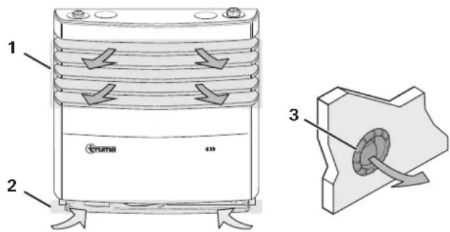
text_image
1 2 Cruma 3Fig. 1
Risk of burning from hot surfaces.
Possible injury / material damage if the heater is operated without a cover. Risk of burn injury from hot surfaces at the heat exchanger.
▶Operate the heater only with the cover fitted.
The cover can become very hot near the warm air outlet (Fig. 1-1).
▶Do not touch the cover during operation.
Risk of fire from flammable liquids.
If flammable liquids come into contact with hot parts of the heater (heating rods, heat exchanger), they may catch fire.
▶Do not place liquids (bottles, glasses) on or above the S-heater.
▶Do not store flammable liquids or spray cans in or above the installation space.
Electric shock from liquids.
If non-flammable liquids get into the control unit, they can cause a short circuit.
▶Do not place liquids (bottles, glasses) on or above the S-heater.
Electric shock from uncovered, damaged electric cables.
If power cables are damaged (Ultraheat, fan):
Switch off the power supply; for example, via fuses or residual current circuit-breakers (RCCB) in the main distribution board of the vehicle. Unplug the line power. Prevent the power supply from being switched back on.
▶Have the power cable replaced by the manufacturer, customer service or an electrician.
Risk of fire from overheated cable drum.
If the electricity for the vehicle is supplied via a cable drum, high current consumption can heat the rolled up cable.
▶Completely unroll the cable from the drum.
3.4 Troubleshooting
▶Have faults repaired without delay and only by an expert.
▶ Only resolve faults yourself if remedies are described in the chapter on "Faults" in these operating instructions.
3.4.1 What must I do if there are unusual noises or smells?
▶Close off the gas supply and switch off the heater.
▶Switch off Ultraheat.
▶Have an expert check the heater.
4 Product Description
The Ultraheat electric additional heater is an accessory for Truma S-heaters and operates with 230 V\~ line power. The additional heater can be operated on its own. For this purpose, three operating levels are available: 500 W, 1000 W and 2000 W. The additional heater can also be used in combination with an S-heater.
4.1 Design
The Ultraheat electric additional heater consists of a heating element (Fig. 2-4), a control unit (Fig. 2-5) and a control panel (Fig. 2-1). The heating element and the control unit are installed in the S-heater (Fig. 2-3) between the heat exchanger and the installation box. The control panel is mounted outside the S-heater in a wall or piece of furniture.
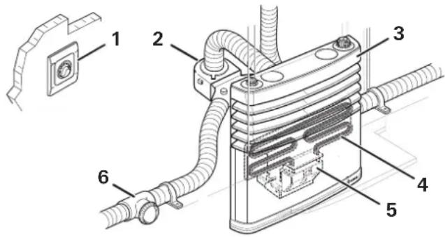
text_image
Technical diagram of a mechanical device with numbered components, likely an electrical or fluid system component.Fig. 2
4.2 Product labelling
The appliance type and the serial number are printed on the type plate.
The type plate of the Ultraheat additional heater is located on the cover of the control unit.
4.3 Function
The heating elements of the electric additional heater heat the air in the S-heater. A fan* (Fig. 2-2) distributes the warm air in the vehicle through warm air ducts and outlets (Fig. 2-6).
The operating level can be adjusted to suit the electrical fuse on the power connection (fuse at the campsite).
The desired room temperature is adjusted using the control panel and the control unit switches the heating elements on an off automatically to reach the desired temperature.
The green LED in the control panel remains on while the temperature is being controlled.
4.4 Operation
S-heaters can be operated with gas and/or the electric additional heater. If the S-heater is operated with gas and the electric additional heater at the same time, the additional heater may switch off to prevent potential overheating.
Generally, heating operation is possible also without fan regardless of operating mode (gas or additional heater). However, in order to ensure that the warm air is distributed evenly and quickly and to lower the surface temperature of the cover, we recommend that you operate the S-heater/Ultraheat with the fan running and a warm air system at all times.
If the Ultraheat additional heater is operated with a remote sensor*, the sensor must not be placed near other heat sources (cookers, lamps, opposite warm air outlets etc.) or in locations where heat can accumulate (below shelves, in corners, behind curtains).
4.5 Control panel
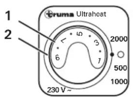
text_image
1 2 Cruma Ultraheat 230 V ~ 5 6 7 8 9 10 2000 500 1000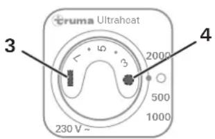
text_image
Cruma Ultraheat 230 V~ 500 1000 2000 4 3Fig. 3
The rotary switch (Fig. 3-2) is used to switch the electric additional heater on an off and to adjust the heating output. A green LED (Fig. 3-4) beneath the rotary switch is lit when the electric additional heater has been switched on. The control knob (Fig. 3-1) is used to adjust the room temperature. The temperature level is shown on a scale of 1 to 9.
① The temperature setting on the control panel (1 – 9) must be determined individually depending on heating requirements and the type of vehicle.
For temperature control, the room temperature is measured with a temperature sensor in the control panel (Fig. 3-3).
Symbol Function
| 2000 Additional heater is heating with 2000 watts | |
| ○ | OFFAdditional heater is off |
| 500 Additional heater is heating with 500 watts | |
| 1000 Additional heater is heating with 1000 watts | |
4.6 Accessories\*
- Extension cable for control panel, 5 m (part no. 34300-01)
- The FFC 2 room temperature sensor, complete with 4 m connection cable (part no. 34203-01), monitors the room temperature regardless of the position of the control panel.
5 Start-Up
During the initial start-up of a brand new appliance, small quantities of fumes and a slight odour may occur briefly.
When the appliance is started up, especially after a long period of non-use, there may be some fumes and/or smell due to dust or dirt for a short time.
▶ Make sure the room is well ventilated.
▶ If necessary, switch on the S-heater fan.
▶ To allow a self-cleaning process, operate the additional heater at its highest operating level for a few minutes.
6 Operation
Before switching on, make sure that the set operating level corresponds to the fuse of the campsite power supply (refer to "Technical Data").
To ensure that warm air is distributed throughout the vehicle quickly and evenly, we recommend that you always operate the heater with the fan running.
① In electrical mode, operate the fan at least at level 3 (manual or automatic).
6.1 Switching on Ultraheat
▶ Set the rotary switch to the desired heating power 500, 1000 or 2000.
The green LED is lit and also indicates the selected temperature setting.
▶ Set the desired temperature level 1 - 9 on the control knob.
6.2 Switching off Ultraheat
▶ Set the rotary switch to ○
The green LED is off.
7 Faults
Listed below are some actions that can be taken to rectify faults. If these actions do not produce the desired result, contact Truma Service.
Ultraheat is switched on but the green LED in the control panel remains off.
Possible cause: No 230 V\~ power supply.
▶ Check 230 V\~ power supply.
- Are other 230 V\~ appliances in the vehicle working?
• Is the line power cable connected?
- Has the fuse in the line power connection (fuse-box at campsite) blown?
- Has the RCCB (residual current circuit-breaker) in the 230 V\~ vehicle distribution board tripped?
- Has a fuse in the 230 V\~ vehicle distribution board blown?
8 Cleaning and Care
The Ultraheat requires no cleaning or care (self-cleaning, refer to "Start-Up").
When cleaning the S-heater with installed additional heater, observe the following additional warnings.

UTION
of burns from hot appliance parts.
Clean only when the S-heater and additional heater are switched off and have cooled down.

UTION
from sharp edges.
In spite of careful manufacturing, the additional heater may contain sharp parts, which could cause cuts.
▶Vear protective gloves while cleaning.

UTION
tric shock from power supply
Before opening the S-heater, disconnect all poles from the 230 V\~ power supply.
Switch off the appliance, switch off at the fuse, unplug the line power.
9 Repair
▶Do NOT attempt to repair the appliance yourself.
▶Have the appliance repaired only by an expert.
10 Disposal and Recycling
The appliance must be disposed of in accordance with the administrative regulations of the respective country in which it is used. National regulations and laws (in Germany, for example, the End-of-life Vehicle Regulation) must be observed.
11 Technical Data
| Variable Value | |
| Voltage | 230 V~, 50 Hz |
| Power consumption at operating level | 500 W: 2.2 A1000 W: 4.5 A2000 W: 8.5 A |
| Weight approx. 2 kg | |
CE
12 WARRANTY
Manufacturer's Warranty (European Union)
12.1 Scope of Manufacturer's Warranty
As the Manufacturer of the appliance, Truma undertakes a warranty towards the Consumer that covers any material and/or manufacturing defects of the appliance.
This Warranty is applicable in EU member states as well as in Iceland, Norway, Switzerland and Turkey. A Consumer is the natural person who was the first one to purchase the appliance from the Manufacturer, OEM or dealer and who neither resold the appliance in a commercial or self-employed professional capacity nor installed it for a third party in such a capacity.
The Manufacturer's Warranty covers any of the aforementioned defects that occur within 24 months upon concluding the purchase agreement between the seller and the Consumer. The Manufacturer or an authorised service partner undertakes to remedy such defects through subsequent fulfilment, i.e. at its discretion either by repairing or replacing the defective item. Defective parts shall become the property of the Manufacturer or the authorised service partner. If the appliance is no longer manufactured at the time of defect notification and if replacement delivery has been opted for, then the Manufacturer may deliver a similar product.
If the Manufacturer remedies a defect under its Warranty commitment, the term of the Warranty shall not start again with regard to the repaired or replaced parts; rather, the original warranty period shall continue to be applicable to the appliance. Only the Manufacturer itself or an authorised service partner shall be entitled to conduct a warranty job. Any costs that occur in the event of a warranty claim shall be settled directly between the authorised service partner and the Manufacturer. The Warranty does not cover additional costs arising from complicated removal or installation jobs on the appliance (e.g. dismantling of furnishings or parts of the vehicle body), and neither does it cover travel expenses incurred by the authorised service partner or the Manufacturer.
No further-reaching claims shall be permitted, especially damage claims presented by the Consumer or third parties. This shall not affect the provisions of the German Product Liability Act (Produkthaftungsgesetz).
The voluntary manufacturer's warranty does not affect the Consumer's legally valid claims for defects against the seller in the relevant country of purchase. In individual countries there may be warranties that can be issued by the relevant dealer (official distributor, Truma Partner). In such cases the warranty can be implemented directly through the dealer from whom the Consumer bought the appliance. The warranty regulations of the country in which the appliance was purchased by the Consumer for the first time shall also be applicable.
12.2 Warranty exclusions
No warranty claim shall be applicable under the following circumstances:
- Improper, unsuitable, faulty or negligent use and any use that is not compliant with the intended purpose
- Improper installation, assembly or commissioning, contrary to operating or installation instructions
- Improper operation or operation contrary to operating or installation instructions, particularly any disregard for maintenance, care or warning notes
- Instances where installations, repairs or any other procedures have been conducted by non-authorised parties
- Consumable materials and parts which are subject to natural wear and tear
- Installation of replacement, supplementary or accessory parts that are not original manufacturer's parts or which have not been approved by the manufacturer. This applies in particular if the appliance is subject to networked control, if the control units or the software have not been approved by Truma or if the Truma control unit (e.g. Truma CP plus or Truma iNetBox) has not been exclusively used for controlling Truma appliances or appliances approved by Truma.
- As a consequence of damage arising from foreign substances (e.g. oil, or plasticisers in the gas), chemical or electrochemical influences in the water, or cases when the appliance has come into contact with unsuitable substances (e.g. chemical products, flammable substances or unsuitable cleaning agents)
- Damage caused by abnormal environmental or unsuitable operating conditions
- Damage caused by force majeure or natural disasters or any other influences not within Truma's responsibility
• Damage resulting from improper transport - End customer's or third-party modifications of the appliance, including any replacement, supplementary or accessory parts, or installation of the same, especially concerning the exhaust gas system or the cowl.
12.3 Making a warranty claim
The warranty must be claimed with an authorised service partner or at the Truma Service Centre. All the relevant addresses and phone numbers can be found at www.truma.com, in the “Service” section.
The Manufacturer's address is:
Truma Service Centre
85640 Putzbrunn, Germany
To ensure a smooth procedure, we would be grateful if you could have the following details ready before contacting us:
• Detailed description of the defect
- Serial number of the appliance
- Date of purchase
The authorised service partner or the Truma Service Centre will then specify the further procedure. To avoid transport damage, the affected appliance must only be shipped by prior arrangement with the authorised service partner or the Truma Service Centre.
If the warranty claim is recognised by the Manufacturer, then the transport expenses shall be borne by the same. If no warranty claim is applicable, the Consumer will be notified accordingly and any repair and transport expenses shall then be the Consumer's liability.
We ask you not to send in an appliance without prior arrangement.
Table des matières
natural_image
3D mechanical component diagram showing a circular feature with a curved arrow indicating rotation (no text or symbols)Fig. 1
text_image
Technical diagram of a mechanical device with numbered components, likely a valve or connector assembly.Fig. 2
natural_image
3D mechanical component diagram showing a circular feature inserted into a housing, with no visible text or symbolsFigura 1
text_image
Technical diagram of a mechanical device with numbered components, likely a valve or connector assembly.Figura 2
text_image
Technical diagram of a mechanical device with numbered components, likely a valve or pump assembly.Afb. 2
6.2 Sluk for Ultraheat 42
7 Fejl 42
natural_image
3D mechanical component diagram showing a circular feature with a curved arrow, labeled with number 3 (no text or symbols beyond label)Fig. 1
text_image
Technical diagram of a mechanical device with numbered components, likely a valve or connector assembly.Fig. 2
4.2 Produktmærkning
6.2 Sluk for Ultraheat
text_image
Technical diagram of a mechanical device with numbered components, likely a valve or pump assembly.Bild 2
4.2 Produktmärkning
natural_image
3D mechanical component diagram showing a circular feature inserted into a housing, with no visible text or symbolsFig. 1
text_image
Technical diagram of a mechanical device with numbered components, likely a valve or connector assembly.Fig. 2
6.2 Apagar Ultraheat
EN Should problems occur, please contact the Truma Service Centre or one of our authorised service partners (see www.truma.com).
In order to avoid delays, please have the unit model and serial number ready (see type plate).