Combi D 4 - Heating TRUMA - Free user manual and instructions
Find the device manual for free Combi D 4 TRUMA in PDF.
| Product type | Warm air heater with integrated water heater |
| Brand | Truma |
| Model | Combi D 4 |
| Category | Heater |
| Fuel | Diesel according to DIN EN 590 |
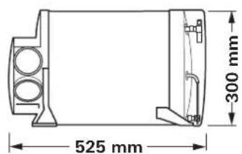
| Dimensions (L x W x H) | 450 x 525 x 300 mm |
| Weight (without water) | 15.8 kg (unit only) / 17.2 kg (with periphery) |
| Power supply | 12 V DC |
| Power consumption | 1.8 - 4 A (heating + water); standby: 0.001 A |
| Heating power | 2,000 / 4,000 W (2 automatic stages) |
| Water heater volume | 10 liters |
| Max. pump / system pressure | 2.8 bar / 4.5 bar |
| Heating time (from 15°C to 60°C) | ≈ 20 min (water only); ≈ 80 min (heating + water) |
| Max. air flow | 287 m³/h |
| Fuel consumption | 220 - 452 ml/h |
| Frost protection | FrostControl (automatic drain valve at 3°C) |
| Included accessories | Control unit (digital or analog), temperature sensor |
| Maintenance | Drain water heater before frost; check exhaust; maintenance every 2 years |
| Safety | Automatic shutoff on fault; overheat protection; do not use in garages |
| Spare parts | Original Truma spare parts |
| Repairability | Repairs by authorized service center only |
| Warranty | 2 years (EU) |
| Application | Motorhomes, caravans (not in buses) |
Frequently Asked Questions - Combi D 4 TRUMA
User questions about Combi D 4 TRUMA
0 question about this device. Answer the ones you know or ask your own.
Ask a new question about this device
Download the instructions for your Heating in PDF format for free! Find your manual Combi D 4 - TRUMA and take your electronic device back in hand. On this page are published all the documents necessary for the use of your device. Combi D 4 by TRUMA.
USER MANUAL Combi D 4 TRUMA
natural_image
Exterior view of a Truma Combi D electric motor (no signage or text beyond branding)text_image
Technical diagram of a mechanical assembly with numbered components and a digital display panel showing measurement data.Bild 1
text_image
Technical diagram of a mechanical device with labeled parts (a, b, c, d) and directional arrows indicating movement or assembly.Bild 3
text_image
T 20 A T 10 ABild 4
Technische Daten
natural_image
Technical line drawing of a mechanical component with dimension标注 (450 mm), no readable text or symbols present.Bild 5

text_image
525 mm 300 mmStörungen
natural_image
Exterior view of a black Trumo network device with two Ethernet ports and a USB port (no visible text or symbols)Bild 7
Truma CP classic
natural_image
Line drawing of a cable and plug assembly with a separate connector (no text or symbols)Bild 9
natural_image
Exterior view of a Truma Combi D electric motor (no signage or text beyond branding)EN Operating instructions
To be kept in the vehicle
Page 02
text_image
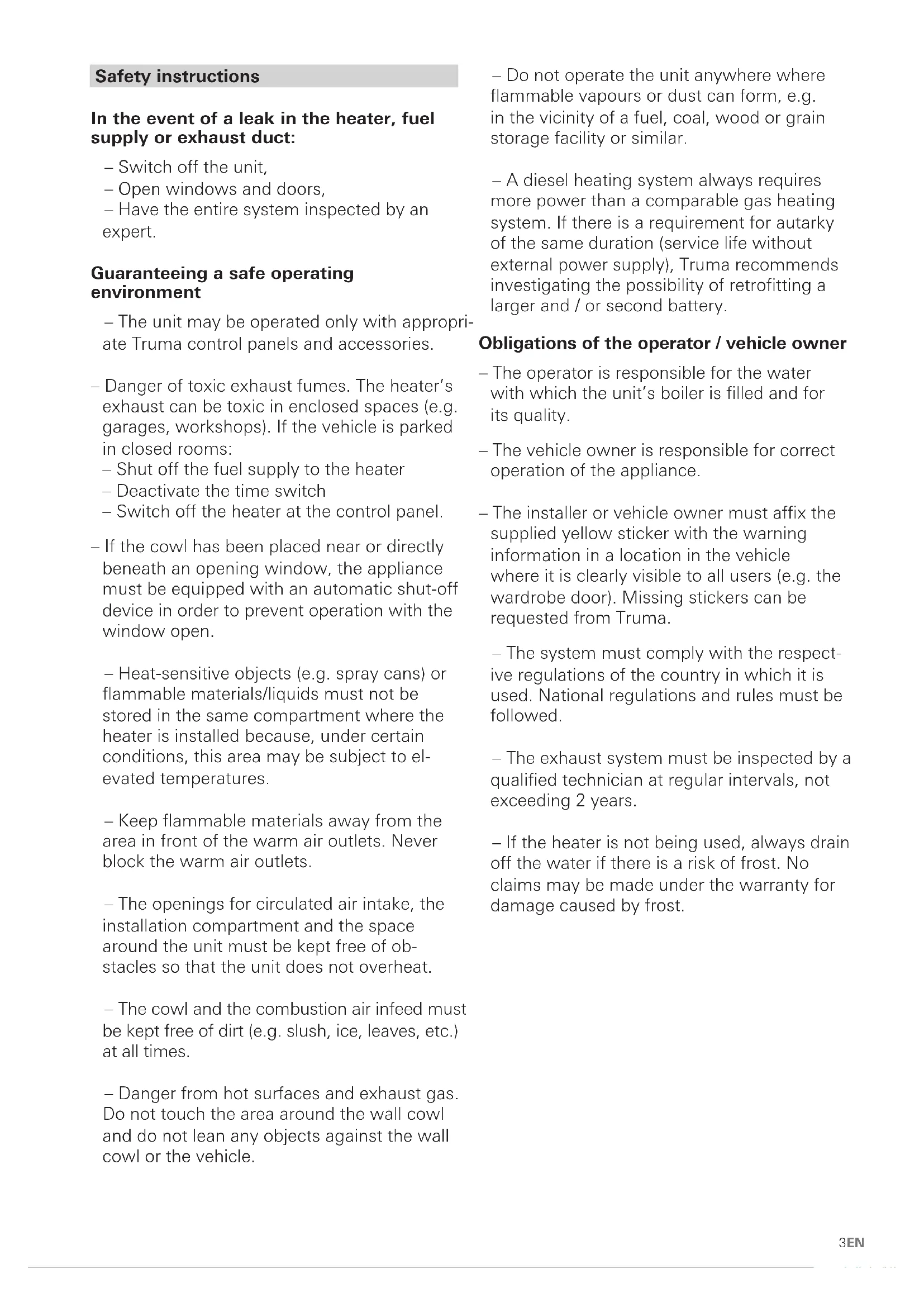
Technical diagram of a mechanical device with numbered components and an analog multimeter on the left.Figure 1
1 Control panel, digital or analogue (no picture)
2 Room temperature sensor
3 Cold water connection
4 Hot water connection
5 Fuel line connection
6 Warm air outlets
7 Circulated air intake
8 Exhaust gas discharge
9 Combustion air infeed
10 Electronic control unit
11 Water container (10 litres)
12 Burner
13 Heat exchanger
14 FrostControl (Safety/drain valve)
Inhaltsverzeichnis
Symbols used .... 2 Intended use .... 2
Safety instructions 3
Function description 5
Fuel supply 5
Fuel quality 5
Fuel at low temperatures 5
Operating instructions
Control panels .... 5 Room temperature sensor .... 5
FrostControl 5
Opening the safety/drain valve 6
Closing the safety/drain valve 6
Automatic opening of the safety/drain valve 6
Filling the boiler 6
Draining the boiler 6
Initial start-up 6
Filling the fuel lines 6
Start-up 6
Switching off 6
Maintenance 7
Fuses 7
Technical data 7
Faults 8
Troubleshooting guide (water supply) 8
Troubleshooting guide (fuel supply) 8
Disposal 8
Accessories 8
Manufacturer's Warranty
(European Union) 9
Symbols used
Symbol indicates possible hazards.
Note containing information and tips.
Intended use
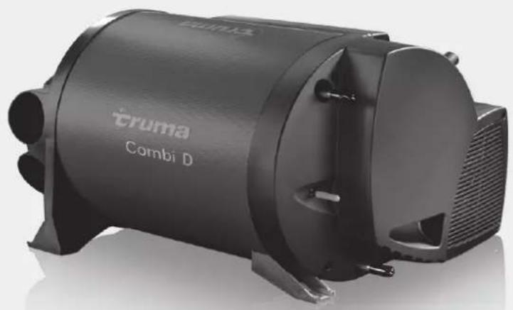
The Combi D 4 diesel heater is a warm air heater with integrated hot water boiler (10 litre volume). This unit was designed for installation in motor homes and caravans. Installation inside buses (vehicle classes M2 and M3) and vehicles is not permitted.
The applicable regulations must be complied with when the equipment is being installed in special vehicles and vehicles for transporting hazardous goods.
An additional altitude kit (part no. 34610-01) is required for long periods of heater operation at altitudes of 1500 to 2750 m.
Safety instructions
In the event of a leak in the heater, fuel supply or exhaust duct:
- Switch off the unit,
- Open windows and doors,
- Have the entire system inspected by an expert.
Guaranteeing a safe operating environment
- The unit may be operated only with appropriate Truma control panels and accessories.
- Danger of toxic exhaust fumes. The heater's exhaust can be toxic in enclosed spaces (e.g. garages, workshops). If the vehicle is parked in closed rooms:
- Shut off the fuel supply to the heater
- Deactivate the time switch
- Switch off the heater at the control panel.
- If the cowl has been placed near or directly beneath an opening window, the appliance must be equipped with an automatic shut-off device in order to prevent operation with the window open.
- Heat-sensitive objects (e.g. spray cans) or flammable materials/liquids must not be stored in the same compartment where the heater is installed because, under certain conditions, this area may be subject to elevated temperatures.
- Keep flammable materials away from the area in front of the warm air outlets. Never block the warm air outlets.
- The openings for circulated air intake, the installation compartment and the space around the unit must be kept free of obstacles so that the unit does not overheat.
– The cowl and the combustion air infeed must be kept free of dirt (e.g. slush, ice, leaves, etc.) at all times.
- Danger from hot surfaces and exhaust gas. Do not touch the area around the wall cowl and do not lean any objects against the wall cowl or the vehicle.
- Do not operate the unit anywhere where flammable vapours or dust can form, e.g. in the vicinity of a fuel, coal, wood or grain storage facility or similar.
- A diesel heating system always requires more power than a comparable gas heating system. If there is a requirement for autarky of the same duration (service life without external power supply), Truma recommends investigating the possibility of retrofitting a larger and / or second battery.
Obligations of the operator / vehicle owner
- The operator is responsible for the water with which the unit's boiler is filled and for its quality.
- The vehicle owner is responsible for correct operation of the appliance.
- The installer or vehicle owner must affix the supplied yellow sticker with the warning information in a location in the vehicle where it is clearly visible to all users (e.g. the wardrobe door). Missing stickers can be requested from Truma.
– The system must comply with the respective regulations of the country in which it is used. National regulations and rules must be followed.
– The exhaust system must be inspected by a qualified technician at regular intervals, not exceeding 2 years.
- If the heater is not being used, always drain off the water if there is a risk of frost. No claims may be made under the warranty for damage caused by frost.
Safe operation
– During heater operation, do not allow the fuel display in the fuel tank to drop to the "low fuel" mark.
If the vehicle fuel tank runs empty, the opening of the fuel removal duct is roughly at the same height as the surface of the fuel. In this state, particularly when the fuel in the vehicle fuel tank is slopping around due to vehicle movement, a large amount of air is sucked in. This leads to an irregular supply of fuel to the heater. The heater burner is unable to maintain clean combustion in this condition, leading to the formation of smoke and odours.
- Ensure that the inside of the vehicle is sufficiently ventilated. When the unit is started up, there may be some smoke and/or smell due to dust or dirt. Especially if it has not been used for a long time.
– The appliance can be used by children aged 8 and over, as well as by persons with reduced physical, sensory or mental capabilities or with a lack of experience and knowledge, provided that they are supervised or have been instructed on how to use the appliance safely and that they understand the resulting risks. Children must not be allowed to play with the appliance.
- The exhaust double duct (exhaust gas sound muffler and extraction duct) must be inspected regularly, particularly following long journeys, to check for any damage and to ensure that the connection is sound. The same applies to the mounting of the heater and the cowl.
Operation while driving
- The heater must not be used during refuelling or in enclosed car parks, in garages, or on ferries.
- To prevent damage to the appliance from spray water, such as when cleaning the vehicle, do not spray water directly into the wall cowl.
Troubleshooting
- If you notice unusual noises or smells, switch off the Combi.
- Danger of fire / explosion if you attempt to use a Combi that has been damaged by flooding or if the vehicle has been involved in an accident. A damaged Combi must be repaired by an expert or be replaced.
– Repairs to the appliance may only be carried out by an expert.
- Have faults repaired by an expert without delay.
- Only carry out repairs yourself if the solution is described in the troubleshooting guide of this manual.
– Following a deflagration (backfire), have the appliance and the exhaust duct checked by an expert.
Maintenance / Repairs / Cleaning
– The appliance may only be repaired and cleaned by an expert.
– Guarantee claims, warranty claims and acceptance of liability will be ruled out in the event of the following:
- Modifications to the appliance (including accessories),
- Modifications to the exhaust duct and the cowl,
- Use of replacement and accessory parts other than original Truma parts,
- Failure to follow the installation and operating instructions.
The appliance's operating permit, and consequently also the vehicle's operating permit in some countries, are also rendered void.
- With a new Combi or if the appliance has not been used for some time, thoroughly rinse all hot/cold water hoses with drinking water before use.
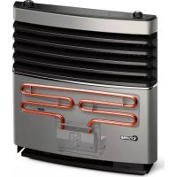
Function description
The Combi D 4 diesel heater is a warm air heater with an integrated hot water boiler (10 litre volume). The burner is fan-assisted, which ensures that operation is problem-free, even when on the move.
In heating and hot water mode the heater can be used to heat the room and heat water up at the same time. If only hot water is required, select hot water mode.
- In hot water mode, the water is heated at the lowest burner setting. Once the water temperature has been reached, the burner switches off.
- In heating and hot water mode, the unit automatically selects the required operating level according to the temperature difference between the temperature set on the control panel and the current room temperature. If the boiler has been filled, the water is automatically heated as well. The water temperature depends on the selected operating mode and the heater output.
At a temperature of approximately 3 °C at the automatic FrostControl safety/drain valve, the valve will open and drain the boiler.
Fuel supply
Fuel quality
The heater requires DIN EN 590 diesel fuel for operation. Operation using bio-diesel (PME, RME or AME) is not permitted.
Fuel at low temperatures
The refineries and filling stations will automatically perform the required adjustments for the usual winter temperatures (winter diesel).
Difficulties can occur at temperatures below 0 °C if the vehicle still has summer diesel in its fuel tank.
If no special diesel fuel is available for use in low temperatures, e.g. winter diesel, then petroleum or benzine should be mixed in with the fuel, in accordance with the instructions given by the vehicle manufacturer.
Temperature
0 °C to -20 °C Winter diesel
-20 °C to -30 °C. Polar or Arctic diesel
Used oil should not be used as an additive!
To guarantee that all fuel lines of the heater unit are filled with winter diesel or another permitted mixture after fuelling, the heater must be operated for at least 15 minutes.
Operating instructions
Read the safety instructions and operating instructions carefully before starting the unit.
Operating instructions can be viewed in offline mode with a mobile device and the Truma App. Download the operating instructions when you have a WiFi connection and save them on your mobile device.
Before initial use, be sure to flush the entire water supply thoroughly with clear water.
The materials of the appliance that come into contact with water are drinking water safe (see manufacturer's declaration: www.truma.com – Manufacturer's Declaration).
Control panels
The control panels are described in separate operating instructions.
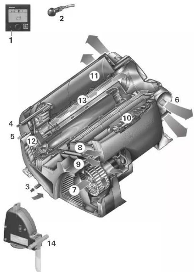
Room temperature sensor
To measure the room temperature, an external room temperature sensor (2) is located in the vehicle. The position of the sensor is determined by the vehicle manufacturer depending on the vehicle model. More information can be found in the operating instructions for your vehicle.
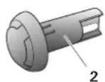
Figure 2
The temperature setting on the control panel depends on personal heating requirements and the design of the vehicle, and must be determined individually.
FrostControl
(safety/drain valve)
FrostControl is a currentless safety/drain valve. When there is a danger of frost, it automatically drains the contents of the boiler through a drainage socket. If excessive pressure is present in the system, pressure will be automatically intermittently equalized through the pressure relief valve.
text_image
Technical diagram of a mechanical device with labeled parts (a, b, c, d) and directional arrows indicating movement or force.Figure 3
a = rotary switch position "On"
b = pushbutton position "Closed"
c = pushbutton position "Drain"
d = drainage socket (led outside through floor of vehicle)
Opening the safety/drain valve
Turn the rotary switch by 180^ until it engages, whereby the pushbutton pops out (position c). The water from the boiler drains through the drainage socket (d).
The FrostControl drainage socket (d) must be free of contamination (slush, ice, leaves, etc.) at all times so the water can drain out easily! No claims may be made under the warranty for damage caused by frost.
Closing the safety/drain valve
Check whether the rotary switch is set to "On" (position a), i.e. parallel to the water connection and engaged.
Close the safety/drain valve by pressing the pushbutton. The pushbutton must engage in position (b) "closed".
Only when the temperature at the safety/drain valve is above approx. 7 °C can it be closed manually with the pushbutton (position b) and the boiler filled.
Truma supplies a heating element (part no. 70070-01) as an accessory, which is plugged into the FrostControl and fixed in place with a retaining bracket. This heating element heats the FrostControl to approx. 10 °C when the Combi D is switched on. This means that the boiler can be filled sooner, irrespective of the temperature in the installation compartment.
Automatic opening of the safety/drain valve
If the temperature at the safety/drain valve is below about 3 ^ , it will open automatically and the pushbutton pops out (position c). The water from the boiler drains through the drainage socket (d).
Filling the boiler
Check whether the safety/drain valve is closed (see "Closing the safety/drain valve").
When the temperature at FrostControl is below approx. 7 °C, first switch on the heater to warm the installation compartment and FrostControl. The safety/drain valve can be closed after several minutes, when the temperature at FrostControl is above 7 °C.
- Switch on the power for the pump assembly (main switch or pump switch).
- Open hot water taps in the kitchen and bathroom (set pre-selecting mixing taps or single-lever fittings to "hot"). Leave the valves open until the boiler has been filled by displacing the air and water is flowing without interruption.
Even if the cold water system alone is operated without the boiler, the boiler will still fill with water. To avoid frost damage, the boiler must be drained via the safety/drain valve, even if it was not operated.
In the event of frost, filling may be prevented by frozen residual water. The boiler can be thawed by turning it on briefly (no more than 2 minutes). Frozen lines can be thawed by heating the interior.
If the boiler is connected to a central water supply (rural or urban connection), a pressure reducer must be used, which will prevent pressures higher than 2.8 bar from occurring.
Draining the boiler
If the motor home / caravan is not being used during the frost period, the boiler must be drained!
- Switch off the power to the pump assembly (main switch or pump switch).
- Open hot water taps in kitchen and bathroom.
In order to check the water that is flowing out, place an appropriate container (capacity 10 litres) beneath the drainage socket (d) of the safety/drain valve.
- Open safety/drain valve (see "Opening the safety/drain valve").
The boiler will now be drained directly to the outside via the safety/drain valve. Check whether all of the water in the boiler (10 litres) has been drained into the container via the safety/drain valve.
No claims may be made under the warranty for damage caused by frost.
Initial start-up
(or when the fuel tank has run empty)
Filling the fuel lines
The heater normally has to be started up several times to fill the fuel lines if an automatic filling device is not being used.
Check to make sure the cowl is unobstructed. Remove any covers that may be present.
Switch off unit at control panel. The unit automatically performs 2 starting attempts (initial start and repeat) per switch-on procedure with a run time of 2 minutes in each case. If no flame is detected after the repeat start, the unit switches to fault and has to be switched off and on again at the control panel.
After a total of 15 unsuccessful starting attempts (initial and repeat start) without forming a flame, the equipment is blocked. To remove the block, please contact the Truma Service Centre or one of our authorised service partners (see www.truma.com).
Check fuel lines and connections for leaks after filling the fuel lines.
Start-up
The interior can be heated with or without water, depending on the setting.
- Check to make sure the cowl is unobstructed. Remove any covers that may be present.
- Fill boiler with water if necessary (see "Filling the boiler").
- Switch on the unit on the control panel.
Switching off
- Switch the heater off on the control panel.
- The switch-off procedure may be delayed by several minutes because of internal heater operations.
Always drain water contents if there is a risk of frost!
Maintenance
Only original Truma parts may be used for maintenance and repair work.
- Even out of season, the heater should be operated once a month for about 10 minutes.
- The safety/drain valve (FrostControl) must be operated regularly (at least twice annually) to remove limescale deposits and to be certain that it is not blocked.
We recommend the use of suitable commercially available products to clean, sterilise and maintain the boiler. Products containing chlorine are not suitable.
The effectiveness of the use of chemicals to combat microorganisms in the appliance can be increased by heating the water in the boiler to 70 °C at regular intervals.
- Set the water temperature to 60^ .
- Switch on the appliance.
Once the water in the boiler has reached a temperature of 60 °C , the burner will switch off. The appliance must stay switched on for at least 30 minutes and no hot water may be removed. The residual heat in the heat exchanger will heat the water up to 70 °C .
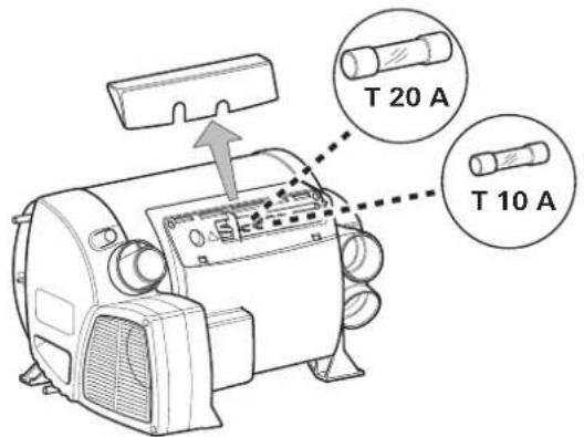
Fuses
The fuses are located in the electronics, beneath the connector cover. When replacing a fuse, be sure to use the same type.
Appliance fuse: 10 A – slow-acting – 5 x 20 mm (T 10 A) Burner fuse: 20 A – slow-acting – 6.3 x 32 mm
text_image
T 20 A T 10 AFigure 4
Technical data
Determined in accordance with Truma test conditions
Fuel
Diesel as per EN 590
Water capacity
10 litres
Heating time from approx. 15 °C to approx. 60 °C
Boiler approx. 20 minutes (measured according to EN 15033) Heater + boiler approx. 80 min.
Pump pressure
max. 2.8 bar
System pressure
max. 4.5 bar
Rated thermal output (automatic operating level) 2000 W / 4000 W
Fuel consumption
220 - 452 ml/h (110 ml/h in normal mode with average heat output of 1000 W)
Air delivery volume (free-blowing without warm air duct) max. 287 m³/h
Power consumption at 12 V
Heater + boiler 1.8 - 4 A (in control mode between "Off" and "Lowest operating level" less than 1.8 A)
Heat up boiler without heating operation max. 1.8 A Stand-by approx. 0.001 A
Heating element - FrostControl (optional): maximum 0.4 A
Weight (without water)
Heater: 15.8 kg
Heater with
peripheral devices: 17.2 kg

Subject to technical changes.
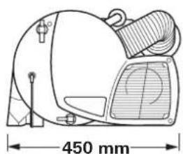
Dimensions
natural_image
Technical line drawing of a mechanical device with dimension标注 (450 mm), no readable text or symbols present.Figure 5
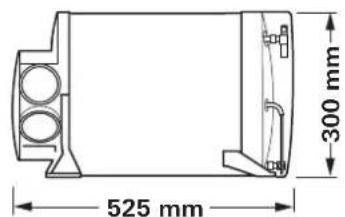
text_image
525 mm 300 mmFaults
Faults - Heater
Descriptions of possible fault causes and a troubleshooting guide can be found in the operating instructions for the control panel that is installed.
Faults – Water supply
Possible fault causes and a troubleshooting guide – See "Troubleshooting guide (water supply)".
Troubleshooting guide (water supply)
| Fault Cause / Remedy | |
| Water taking an extremely long time to heat up. | Water container furred. / Descale water system (see maintenance). |
| Water running away – boiler cannot be filled. | Safety/drain valve open. / Close safety/drain valve. |
| Boiler cannot be drained, even though the safety/drain valve is open. | Safety/drain valve draining socket blocked. / Check opening for soiling (slush, ice, leaves etc.) and remove if necessary. |
| Water dripping/flowing from drainage socket of safety/drain valve. | Water pressure too high. / Check pump pressure (max. 2.8 bar). If the boiler is connected to a central water supply (rural or urban connection), a pressure reducer must be used that will prevent pressures higher than 2.8 bar from occurring. |
| After the heater has been switched off, the FrostControlopens. | At temperatures of less than approx. 3 °C the FrostControl opens automatically / Switch heater on / Without heater operation the FrostControl cannot be closed again until the temperature reaches approx. 7 °C / Use heating element for FrostControl. |
| The FrostControl can no longer be closed. | Temperature at FrostControl less than approx. 7 °C / Switch heater on / Without heater operation the FrostControl cannot be closed again until the temperature reaches approx. 7 °C. |
| Rotary switch is not set to “Operation”. / Turn the rotary switch of the FrostControl to “Operation”, then press the pushbutton until it engages. | |
Troubleshooting guide (fuel supply)
Error Cause / Remedy
| Large amounts of smoke on the cowl for more than 1 minute after the equipment is started. |
Fuel supply malfunction. Improper installation. Limited combustion air infeed Fire hazard! Do not use the equipment any longer. Contact customer service.
If these actions do not remedy the problem, please contact Truma Service.
Disposal
The appliance must be disposed of in accordance with the administrative regulations of the respective country in which it is used. National regulations and laws (in Germany, for example, the End-of-life Vehicle Regulation) must be observed.
In other countries, the relevant regulations must be observed.
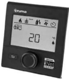
Accessories
Truma CP plus
Digital control panel Truma CP plus with automatic air conditioning system for the iNet-capable Truma heaters Combi and Truma air conditioning systems Aventa eco, Aventa comfort (from serial number 24084022 – 04/2013), Saphir comfort RC and Saphir compact (from serial number 23091001 – 04/2012)
- The automatic air conditioning system function automatically controls the heater and the air conditioning system until the required temperature is reached in the vehicle.
- With the Truma iNet Box extension, all TIN-Bus-capable Truma appliances can also be controlled via the Truma App.
text_image
tnma 20 °C iNet HEDDYFigure 6
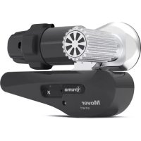
Truma iNet Box
The Truma iNet Box for simple networking and control of Truma appliances with a smartphone or tablet computer using the app.
– Simple installation and start-up via the Truma App
- Can be extended with the update function, which ensures that it is always up to date

natural_image
Exterior view of a network device labeled 'Truma' with ports and connectors (no readable text beyond branding)Figure 7
Truma CP classic
Analogue control panel for Combi D 4
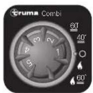
Figure 8
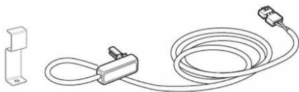
Heating element for FrostControl
Heating element with 1.5 m connector cable and retaining bracket.
natural_image
Line drawing of a cable and connector assembly with a small bracket (no text or symbols)Figure 9
Other accessories (not illustrated) for control panels
- The cable is available in different lengths.
Manufacturer's Warranty (European Union)
1. Scope of Manufacturer's Warranty
As the Manufacturer of the unit, Truma undertakes a warranty towards the Consumer that covers any material and/or manufacturing defects of the unit.
This Warranty is applicable in EU member states as well as in Iceland, Norway, Switzerland and Turkey. A Consumer is the natural person who was the first one to purchase the unit from the Manufacturer, OEM or dealer and who neither resold the unit in a commercial or self-employed professional capacity nor did he or she install it for a third party in such a capacity.
The Manufacturer's Warranty covers any of the aforementioned defects that occur within 24 months upon concluding the purchase agreement between the seller and the Consumer. The Manufacturer or an authorised service partner undertakes to remedy such defects through subsequent fulfilment, i.e. at its discretion either by repairing or replacing the defective item. Any defective parts shall become the property of the Manufacturer or the authorised service partner. If the unit is no longer manufactured at the time of defect notification and if replacement delivery has been opted for, then the Manufacturer may deliver a similar product.
If the Manufacturer remedies a defect under its warranty commitment, the term of the Warranty shall not recommence anew with regard to the repaired or replaced parts; rather, the original warranty period shall continue to be applicable to the unit. Only the Manufacturer itself and an authorised service partner shall be entitled to conduct a warranty job. Any costs that occur in the event of a warranty claim shall be settled directly between the authorised service partner and the Manufacturer. The Warranty does not cover additional costs arising from complicated removal or installation jobs on the unit (e.g. dismantling of furnishings or parts of the vehicle body), and neither does it cover travel expenses incurred by the authorised service partner or the Manufacturer.
No further-reaching claims shall be permitted, especially damage claims presented by the Consumer or third parties. This provision shall not affect the validity of the German Product Liability Act (Produkthaftungsgesetz).
Neither does the voluntary Manufacturer's Warranty affects the Consumer's legally applicable claims for defects towards the seller in the relevant country of purchase. In individual countries there may be warranties that can be issued by the relevant dealer (official distributor, Truma Partner). In such cases the warranty can be implemented directly through the dealer from whom the Consumer bought the unit. The warranty regulations of the country in which the unit was purchased by the Consumer for the first time shall also be applicable.
2. Warranty exclusions
No warranty claim shall be applicable under the following circumstances:
- Improper use, contrary to the specified use
- Improper installation, assembly or commissioning, contrary to operating or installation instructions
- Improper operation, contrary to operating or installation instructions, particularly maintenance, care and warning notes
– Instances where repairs, installations or any other procedures have been conducted by non-authorised partners - Consumable materials and parts which are subject to natural wear and tear
- Installation of replacement, supplementary or accessory parts that are not original Manufacturer's parts and which have thus caused a defect
- Damage arising from foreign substances (e.g. oils, plasticisers in the gas), chemical or electrochemical influences in the water, or cases when the unit has come into contact with unsuitable substances (e.g. chemical products, unsuitable cleaning agents)
– Damage caused by abnormal environmental or unsuitable operating conditions
– Damage caused by force majeure or natural disasters or any other influences not within Truma's responsibility
– Damage resulting from improper transport
3. Making a warranty claim
The warranty must be claimed with an authorised service partner or at the Truma Service Centre. All the relevant addresses and phone numbers can be found at www.truma.com, in the "Service" section.
To ensure a smooth procedure, we should be grateful if you could have the following details ready before contacting us:
– Detailed description of the defect
- Serial number of the unit
– Date of purchase
The authorised service partner or the Truma Service Centre will then specify the further procedure. To avoid transport damage, the affected unit must only be shipped upon prior arrangement with the authorised service partner or the Truma Service Centre.
If the warranty claim is recognised by the Manufacturer, then the transport expenses shall be borne by the same. If no warranty claim is applicable, the Consumer will be notified accordingly and any repair and transport expenses shall then be the Consumer's liability. We must ask you not to send in a unit without prior arrangement.
EN Should problems occur, please contact the Truma Service Centre or one of our authorised service partners (see www.truma.com).
In order to avoid delays, please have the unit model and serial number ready (see type plate).
Combi D 4
natural_image
Exterior view of a Truma Combi D electric motor (no signage or text beyond branding)FR Mode d'emploi
text_image
Technical diagram of a mechanical device with numbered components and an analog multimeter on the left.Figure 1
text_image
Technical diagram of a mechanical device with labeled parts (a, b, c, d) and directional arrows indicating movement or assembly.Figure 3
text_image
T 20 A T 10 AFigure 4
natural_image
Exterior view of a black foldable network device labeled 'iTruma' with ports and connectors (no readable text beyond branding)Figure 7
Truma CP classic
natural_image
Line drawing of a cable and plug assembly with a small bracket (no text or symbols)Figure 9
natural_image
Exterior view of a Truma Combi D electric motor (no signage or text beyond branding)text_image
Technical diagram of a mechanical device with numbered components and an analog multimeter on the left.Fig. 1
text_image
Technical diagram of a mechanical device with labeled parts (a, b, c, d) and directional arrows indicating movement or assembly.Fig. 3
text_image
T 20 A T 10 AFig. 4
Specifiche tecniche
natural_image
Technical line drawing of a mechanical component with dimension标注 (450 mm), no readable text or symbols present.Fig. 5

text_image
525 mm 300 mmGuasti
Guasti - stufa
natural_image
Exterior view of a black Truma Ethernet box with ports and indicator lights (no readable text or symbols beyond branding)Fig. 7
Truma CP classic
natural_image
Line drawing of a cable and connector assembly with a bracket (no text or symbols)Fig. 9
natural_image
Exterior view of a Truma Combi D electric motor (no signage or text beyond branding)text_image
Technical diagram of a mechanical device with numbered components and an analog multimeter on the left.Figura 1
text_image
Technical diagram of a mechanical device with labeled parts (a, b, c, d) and directional arrows indicating movement or assembly.Figura 3
text_image
T 20 A T 10 AFigura 4
Datos técnicos
natural_image
Exterior view of a black iNet Box network device with ports and connectors (no visible text or symbols)Figura 7
Truma CP classic
natural_image
Line drawing of a cable and connector assembly with a bracket (no text or symbols)Figura 9
natural_image
Exterior view of a Truma Combi D electric motor (no signage or text beyond branding)DA Brugsanvisning
text_image
Technical diagram of a mechanical device with numbered components and an analog multimeter on the left.Fig. 1
text_image
Technical diagram of a mechanical device with labeled parts (a, b, c, d) and directional arrows indicating movement or assembly.Fig. 3
a = Drejekontakt position »drift«
b = Trykknap position »lukket«
text_image
T 20 A T 10 AFig. 4
Tekniske data
fundet iht. Truma kontrolbetingelser
Brændstof
Diesel iht. EN 590
Vandindhold
10 liter
natural_image
Technical line drawing of a mechanical component with dimension标注 (450 mm), no readable text or symbols present.Fig. 5

text_image
525 mm 300 mmFejl
Fejl - varmeanlæg
natural_image
Exterior view of a Truma network device with ports and connectors (no readable text or symbols beyond branding)Fig. 7
Truma CP classic
Analog betjeningsdel til Combi D 4
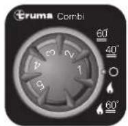
Fig. 8
natural_image
Line drawing of a cable and connector assembly with a small bracket (no text or symbols)Fig. 9
natural_image
Exterior view of a Truma Combi D electric motor (no signage or text beyond branding)SV Bruksanvisning
text_image
Technical diagram of a mechanical device with numbered components and a digital display panel showing measurement data.Bild 1
text_image
Technical diagram of a mechanical device with labeled parts (a, b, c, d) and directional arrows indicating movement or assembly.Bild 3
text_image
T 20 A T 10 ABild 4
Tekniska data
natural_image
Technical line drawing of a mechanical component with dimension标注 (450 mm), no readable text or symbols present.Bild 5
text_image
525 mm 300 mmFel
Fel - värmare
natural_image
Exterior view of a Truma Ethernet device (no visible text or symbols on the device body)Bild 7
Truma CP classic
natural_image
Line drawing of a cable and connector assembly with a bracket (no text or symbols)Bild 9