Mover smart A - Heating TRUMA - Free user manual and instructions
Find the device manual for free Mover smart A TRUMA in PDF.
| Product type | Maneuvering system for caravan |
| Brand | Truma |
| Model | Mover smart A |
| Weight (without battery) | 32 kg |
| Power supply | 12 V DC, lead-acid or gel battery (not included) |
| Maximum current consumption | 125 A |
| Average current consumption | 35 A |
| Standby current (plugged/unplugged) | 60 mA / 30 mA |
| Maximum speed | 0.15 m/s |
| Remote control frequency | 868 MHz, class 1 |
| Remote control battery | 9 V MN 1604 |
| Intended use | Single-axle caravans, total weight up to 2000 kg |
| Maximum hill grade capability | 13 % (2000 kg) or 25 % (1200 kg) |
| Main functions | Roller engagement/retraction, forward/reverse maneuvering, on-the-spot rotation, emergency stop |
| Safety | Emergency stop (red button), automatic remote control shut-off (3 min), battery isolation switch, manual emergency retraction |
| Maintenance | Cleaning with water jet and soft brush, regular check of roller/tire distance (20 mm), inspection by specialist every 2 years |
| Spare parts and repairability | Use only genuine Truma parts; repair by an authorized specialist |
| Manufacturer warranty | 24 months (EU, Iceland, Norway, Switzerland, Turkey) |
| Approval | ABE (Germany) |
| Delivery contents | Integrated maneuvering system, remote control, 20 mm spacer plate, hex socket wrench, battery isolation switch (depending on version), instruction manual |
Frequently Asked Questions - Mover smart A TRUMA
User questions about Mover smart A TRUMA
0 question about this device. Answer the ones you know or ask your own.
Ask a new question about this device
Download the instructions for your Heating in PDF format for free! Find your manual Mover smart A - TRUMA and take your electronic device back in hand. On this page are published all the documents necessary for the use of your device. Mover smart A by TRUMA.
USER MANUAL Mover smart A TRUMA
natural_image
Exterior view of a Cruma smart vacuum cleaner with visible branding and control buttons (no text or symbols on device body)DE Gebrauchsanweisung Seite 02
Im Fahrzeug mitzuführen
EN Operating instructions Page 22
To be kept in the vehicle
FR Mode d'emploi Page 41
À garder dans le véhicule
IT Istruzioni per l'uso
Pagina 61
Da tenere nel veicolo
Inhaltsverzeichnis
text_image
Technical diagram of a vehicle's internal components with numbered parts and labeled partsAbb. 1
text_image
Technical diagram of a mechanical device with numbered parts labeled 1, 2, 3, and 4Abb. 2
text_image
Technical diagram showing two mechanical assembly configurations labeled 1 and 2, with components like a knob and adjustment knobs.Abb. 4
natural_image
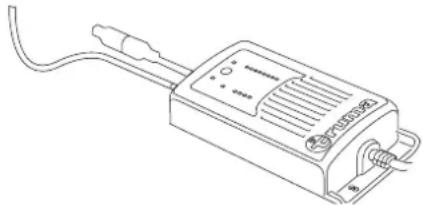
Line drawing of a rectangular electronic device with leads and ports, no text or symbols presentAbb. 5
4.5 Fernbedienung
text_image
Diagram showing battery charging process with labeled components and directional arrow indicating charging directionAbb. 7
natural_image
Illustration of a hand gripping a tool with an upward arrow, no text or symbols presentAbb. 8
text_image
Technical diagram of a mechanical linkage assembly with numbered componentsAbb. 9
natural_image
Mechanical assembly diagram showing a rotating component with arrows indicating motion (no text or symbols)Abb. 11
natural_image
Technical line drawing of a mechanical device with circular components and a gear-like component (no text or symbols)Abb. 13
text_image
Technical diagram showing a mechanical assembly with labeled components and a control panel for 'truma' operation.Abb. 14
natural_image
Technical line drawing of a mechanical device with a circular component and a curved handle (no text or symbols)Abb. 15
natural_image
Simple gray icon of a device with an upward arrow, no text or symbols present▶Rückwärts
text_image
Gruma Mover smart
natural_image
Simple gray icon of a device with a downward arrow, no text or symbols presentAbb. 17
natural_image
Silhouette of a device with a curved arrow indicating rotation or movement (no text or symbols)▶Rechts vor
text_image
Bruma Mover smartAbb. 19
natural_image
Silhouette of a device with a curved arrow and circular button, no text or symbols presentLinks zurück
text_image
Gruma Mover smart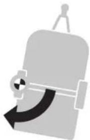
natural_image
Silhouette of a person holding a device with a curved arrow indicating rotation (no text or symbols)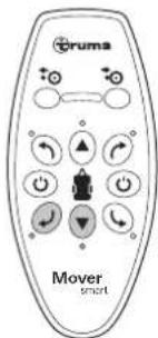
text_image
Gruma Mover smart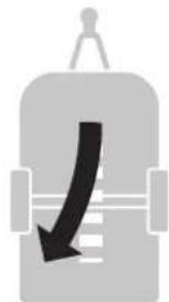
natural_image
Simple gray icon of a container with a downward arrow, no text or symbols presentnatural_image
Simple gray icon of a device with a curved arrow, no text or symbols presentnatural_image
Simple gray icon of a device with a black curved arrow pointing downward (no text or symbols)Abb. 21
natural_image
Simple gray icon of a vehicle with a curved arrow indicating direction (no text or symbols)Abb. 25
natural_image
Abstract gray icon with a curved arrow and circular shape, no text or symbols presentnatural_image
Simple gray icon of a bottle with an arrow pointing upward, no text or symbols present.Abb. 26
text_image
Gruma Mover smart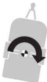
natural_image
Abstract gray icon of a stylized object with curved arrows, no text or symbols presenttext_image
Diagram of a mechanical linkage system with numbered components and directional arrows indicating motion or movement.Abb. 28
text_image
Technical diagram of a mechanical device with numbered components and directional arrows indicating motion or assembly.Abb. 30
natural_image
Technical line drawing of a mechanical device with circular components and a gear-like component (no text or symbols)Abb. 31
text_image
Technical diagram of a mechanical device with labeled parts and directional arrows indicating motion or assembly.Abb. 32
natural_image
Mechanical assembly diagram showing a rotating shaft and housing with a black arrow indicating motion (no text or symbols)Abb. 34
1 About these instructions 23
1.1 Document number 23
1.2 Validity 23
1.3 Target group 23
1.4 Symbols and displays 23
1.5 Warnings 23
1.6 Abbreviations and glossary 23
1.7 Supplied 23
1.8 Accessories 23
2 Safety instructions 24
2.1 General safety 24
2.2 Obligations of the operator/vehicle owner .. 24
2.3 Safe operation 24
2.4 What to do if malfunctions occur 25
3 Intended use 25
3.1 Proper use 25
3.2 Use that is not compliant with the intended purpose 25
3.3 Installation, removal, conversion 25
4 Product description 26
4.1 Setup 26
4.2 Product label 27
4.3 Function 27
4.4 Power supply 27
4.5 Remote control 27
5 Operation 29
5.1 Uncoupling the towing vehicle 29
5.2 Switch on the manoeuvring system 29
5.3 Engage the manoeuvring system 30
5.4 Manoeuvring the caravan 31
5.5 Coupling to the towing vehicle 32
5.6 Disengage the manoeuvring system 33
5.7 Disengage the manoeuvring system manually (emergency disengagement) 34
5.8 Switch off the manoeuvring system 34
6 Malfunctions 35
6.1 Troubleshooting guide 35
6.2 Pairing the electronic control unit with the radio remote control 36
7 Care and maintenance 36
7.1 12 V battery care 36
7.2 Remote control care 36
7.3 Tyre care 37
7.4 Drive unit care 37
7.5 Maintaining the manoeuvring system 37
7.6 Maintaining the tyres 37
7.7 Maintaining the control unit 37
7.8 Check the gap between the rollers and the tyres 37
7.9 Standstill for an extended period of time ..... 37
8 Repair 38
9 Disposal and recycling 38
9.1 Disposing of the manoeuvring system 38
9.2 Disposing of remote control and batteries .... 38
10 Technical data 39
11 Warranty 39
11.1 Scope of Manufacturer's Warranty 39
11.2 Exclusion of warranty 40
11.3 Making a warranty claim 40
1 About these instructions
These operating instructions form part of the product.
▶Always keep the operating instructions in the vehicle.
▶ Make the safety instructions accessible to other users too.
1.1 Document number
The document number of these operating instructions is printed on each inside page in the footer and on the back.
The document number consists of
• Article number (10 numbers)
- Revision status (2 numbers)
• Publication date (month/year)
1.2 Validity
These operating instructions apply exclusively to the Mover smart A.
1.3 Target group
These operating instructions are aimed at users.
☑nder-specific language has not been used to improve legibility. Corresponding terms apply to people of all genders in the interests of equal treatment.
1.4 Symbols and displays
Symbol Meaning
| Warning of hazards for people | |
| Technician | |
| Additional information to help with understanding or optimising work processes. | |
| Symbol for an action step.Something has to be done here. | |
| * | Optional parts |
| (Fig. 3-1) | Reference to an imageE.g. Figure 3 – number 1 |
1.5 Warnings
Warnings are used in these operating instructions to warn of property damage and personal injury.
▶Always read and observe warnings.
| Warning word Meaning | |
| Risk | Hazards for people.Failure to observe this information will lead to fatal or severe injury. |
| WARNING | Hazards for people.Failure to observe this information will lead to fatal or severe injury. |
| CAUTION | Hazards for people.Failure to observe this information may lead to minor injury. |
| NOTICE | Information about preventing property damage |
The installer or vehicle owner must apply the yellow sticker with the warning information, which is enclosed with the appliance, in a location in the vehicle where it is clearly visible to all users (e.g. the wardrobe door). Missing stickers can be requested from Truma.
1.6 Abbreviations and glossary
| Word Meaning | |
| LED | Light-emitting diode |
| ABE General operating permit | |
1.7 Supplied
- Operating instructions on the functionality of the manoeuvring system with associated safety instructions
• ABE - Installed manoeuvring system including remote control for controlling the manoeuvring system
- 20 mm spacer plate for regularly checking the gap between tyres and drive rollers
- If available: battery cut-off switch for establishing / disconnecting the power supply to the entire system
- Hexagonal socket spanner for manual emergency disengaging of the drive units
1.8 Accessories
Power Set BC
2 Safety instructions
2.1 General safety
Failure to comply with the regulations set out in the operating instructions may lead to severe property damage and serious harm to health or danger of death.
Read the safety instructions and follow them exactly to prevent danger, personal injury and property damage.
Observe locally applicable laws, directives and standards relating to using and operating the appliance.
2.2 Obligations of the operator / vehicle owner
Prerequisite for operation
Who is allowed to operate the manoeuvring system? The manoeuvring system may be operated only by persons of legal age who have been made aware of the potential risks when using the product and who are able to safely operate the manoeuvring system together with the vehicle.
▶Never allow children to play with the manoeuvring system.
▶Never use the manoeuvring system under the influence of drugs, alcohol or medication.
In order to ensure that the manoeuvring system operates correctly, the gap between the tyres and the disengaged drive rollers must be 20 mm. All tyres must be inflated to the same pressure in accordance with manufacturer's instructions Tyre wear or the fitting of new tyres may make it necessary to readjust the gap between the drive rollers and the tyres.
▶Regularly check the gap between the drive roller and the tyre
▶Regularly check the tyre pressure
All wheels and tyres on the caravan must be of the same size and type. If this is not observed, safe operation is not guaranteed.
Before using the manoeuvring system for the first time, practice with it to familiarise yourself with the functions of the remote control and of the manoeuvring system.
Inspect the manoeuvring system for damage before use. The manoeuvring system must not be used if it is damaged.
Before each use of the manoeuvring system, check the tyres and drive rollers; remove any sharp stones and similar objects between the drive rollers and tyres.
2.3 Safe operation
If the drive rollers are not completely engaged, the caravan cannot be controlled.
▶Always completely engage the drive rollers.
When engaging and disengaging and while operating the manoeuvring system, care must be taken to ensure that no hair, parts of the body, clothing or other parts on the body can become caught in moving parts (such as drive rollers).
In order to avoid tilting the caravan,
When manoeuvring on slopes the drawbar should be pointed downwards (downhill).
During manoeuvring, the distance between the radio remote control and the middle of the caravan must not exceed 10 m.
the to the characteristic properties of a radio signal, it may be interrupted by terrain / objects. This reduces reception quality in small areas around the caravan, as a result of which the operation of the manoeuvring system may be briefly interrupted.
▶If necessary, reduce the gap between the control unit and the remote control
▶Switch the remote control off and back on again
People inside the caravan:
▶Only move caravans with a manoeuvring system when there is nobody inside.
People outside the caravan:
There must be no persons (particularly children) inside the turning and movement range (manoeuvring range) of the caravan.
Maintaining an overview of the situation:
▶Ensure that there is sufficient visibility and space when manoeuvring.
Never tow the caravan with the drive rollers engaged, as this may cause damage to the tyres, the towing vehicle and the drive units, as well as to attachments.
After manoeuvring, always engage the parking brake and block the wheels (especially on slopes) (e.g. with blocking wedges) first of all. Then disengage the drive rollers from the tyres.
The manoeuvring system is not suitable for use as a parking brake for the parked caravan.
When the manoeuvring system is switched off using the remote control, the control unit remains in standby. To completely switch it off, the battery must be disconnected or isolated from the power supply via a previously installed battery cut-off switch.
Do not put the ready-to-operate remote control in your pocket or lay it down, otherwise functions could be triggered accidentally via buttons or the control knob or slide control.
Always protect the radio remote control from unauthorised access (paying particular attention to children).
General instructions relating to the manoeuvring system
When jacking up the caravan, the manoeuvring system must not be used as a support point, as this could damage the drive unit and the vehicle.
The empty weight of the vehicle increases by the weight of the manoeuvring system, which reduces the payload of the vehicle.
▶Do not exceed the permissible gross weight when loading the caravan.
Depending on the weight of the caravan, the manoeuvring system can only overcome obstacles (e.g. kerbs) from a height of approx. 2 cm using auxiliary equipment (e.g. wedges).
Levelling ramps must not exceed an incline of 25% (14°). Otherwise, depending on the weight of the vehicle, it may not be possible to overcome the incline or the tyre tread may be damaged.
▶Levellers or tyre protection systems to prevent flat-spotting often have a steeper incline and are not suitable for use with a manoeuvring system.
Sensitive objects such as cameras, DVD players etc. must not be kept in the stowage box near the control unit or the motor cables, as the powerful electromagnetic fields may damage them.
2.4 What to do if malfunctions occur
Emergency stop
The red push-button (image) on the remote control (OFF) is also used as an "emergency stop button".
Press the red push-button immediately in case of noticeable problems, e.g. uncontrolled behaviour of the manoeuvring system.
3 Intended use
3.1 Proper use
The Mover smart A is a manoeuvring system which allows a caravan to be manoeuvred without the aid of the towing vehicle.
The Mover smart A was designed for use on single-axle caravans with a gross weight of up to 2000 kg.
The caravan may only be manoeuvred with the manoeuvring system on campsites and private property.
3.2 Use that is not compliant with the intended purpose
The caravan must not be manoeuvred with the manoeuvring system on public roads.
The manoeuvring system may only be used for caravans. Manoeuvring of other trailers, such as boat trailers, horsebox trailers, market trailers, construction trailers or similar items, is prohibited.
3.3 Installation, removal, conversion
Only competent and trained people (experts) are permitted to install and repair the Truma product and to carry out the function test, at the same time observing the installation and operating instructions and the currently recognised technical regulations. Experts are people who, based on their specialist instruction and training, their knowledge and experience with Truma products and the relevant standards, can carry out the necessary work properly and identify potential hazards.
People who are not experts should observe the following:
▶Do not mount the appliance, do not install it in other locations and do not install it in other vehicles.
▶Do not dismantle, convert or repair the appliance yourself.
▶Installation, removal or conversion work may only be carried out by experts.
4 Product description
4.1 Setup
4.1.1 Setup of the entyre system
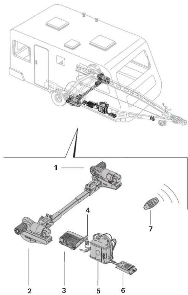
The manoeuvring system consists of two separate drive units, each with its own 12 V DC motor. These units are mounted on the frame of the vehicle in the immediate vicinity of the wheels, and are connected by a lateral bar.
text_image
Technical diagram of a vehicle's internal components with numbered parts labeled 1 through 7Fig. 1
1 Left drive unit (in the driving direction)
2 Right drive unit (in the driving direction)
3 Control unit (illustration serves as an example)
4 Isolating switch
5 Battery
6 Charger
7 Remote control
4.1.2 Setup of the drive unit
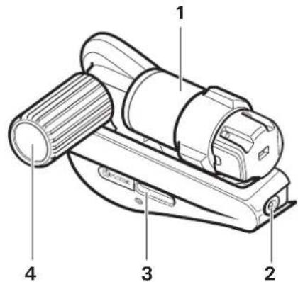
text_image
Technical diagram of a mechanical device with numbered parts labeled 1 to 4Fig. 2
1 Electric motor
2 Emergency disengaging mechanism
3 status display Engaging and disengaging
4 Drive roller
4.1.3 Setup of the power supply

WARNING
Fire hazard due to the control unit being covered inside the caravan
If the control unit is inadequately ventilated, it may overheat during operation.
▶ Adequately ventilate the control unit.
▶ Do not cover the control unit.
Drawing serves as an example (Mover XT control unit)
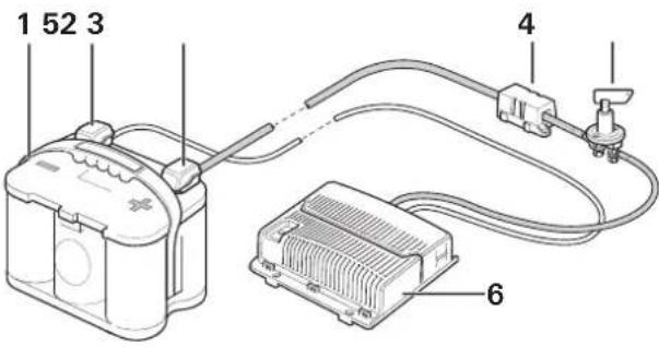
text_image
1 52 3 4 6Fig. 3
1 Battery
2 Negative terminal
3 Positive terminal
4 Fuse
5 Isolating switch
6 Remote control
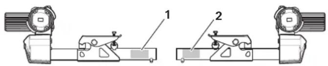
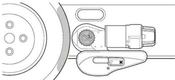
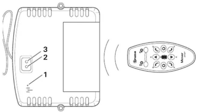
4.2 Product label
The appliance type and serial number are printed on the type plate.
Type plate
To ensure that the general operating permit (ABE) is valid, the type plates must be present on the left and right of each of the mounting tubes.
text_image
Technical diagram showing two mechanical assembly configurations labeled 1 and 2, with components like rollers and clamps.Fig. 4
The type plate of the remote control can be found in the remote control's battery compartment.
The type plate of the control unit is located on the underside of the control unit.
4.3 Function
Coping with inclines (max. climbing ability)
The Mover smart A has been designed to cope with inclines of up to 13 % bearing a gross weight of 2000 kg or 25 % bearing a gross weight of 1200 kg on a suitable surface.
⑧ % = 13 metre difference in altitude over a distance of 100 metres
Once the drive rollers have been engaged against the tyres using the remote control, the manoeuvring system is ready for operation.
Manoeuvring is carried out exclusively via the remote control, which transmits radio signals to the control unit. A separately installed 12 V lead-acid battery or suitable lead-gel battery (not supplied) provides the control unit with electrical power.
4.4 Power supply
▶Always observe the operating instructions and the "Safety instructions" prior to starting. The vehicle user is responsible for correct operation of the device.
4.4.1 Power supply
For optimum operation, we recommend the Truma PowerSet BC and high-performance Optima ^® batteries.
Body-mounted batteries (caravans with self-sufficient power supply with correspondingly large capacity; see table below) are also suitable.
Batteries
NOTICE
Malfunctions during operation due to incorrect power source
To guarantee proper operation of the manoeuvring system, it may only be operated with a charged battery ( ≥ 12 V).
▶ Operation with a charger as power source is not possible and prohibited.
Recommended battery capacities
The 12 V battery used must be certified in accordance with the national standards and regulations of the country of use and in accordance with the manufacturer's installation instructions. The battery must be dimensioned in accordance with the technical requirements of the manoeuvring system.
Starter batteries are not suitable.
Batteries with greater capacity allow the manoeuvring system to be used for longer.
| Round cell technology | Gel / AGM | Lead-acid battery (liquid electrolyte) | |
| Mano-euvring system | Capacity in Ah | ||
| Smart A 55 70 80 | |||
Charger
For optimum battery charging, we recommend the Truma BC 10 charger (a component of the PowerSet BC), which is suitable for all battery types up to 200 Ah.
natural_image
Line drawing of a rectangular electronic device with wires and connectors (no text or symbols)Fig. 5
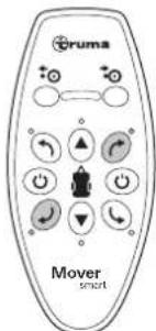
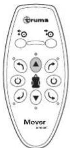
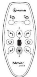
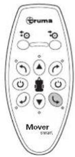
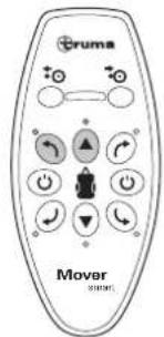
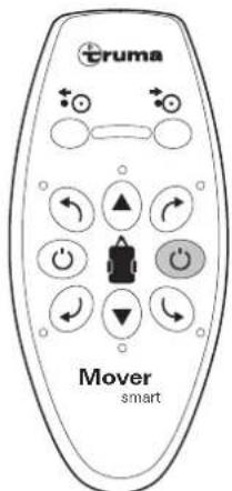
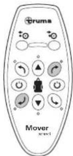
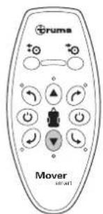
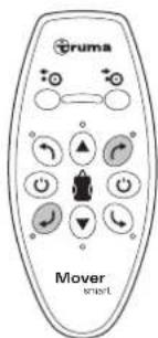
4.5 Remote control
4.5.1 The remote control's functions
NOTICE
Damage to the remote control due to moisture or heat
If moisture gets into the remote control or it is exposed to strong sunlight for too long, this can damage the remote control.
▶ Protect the remote control from moisture.
▶ Protect the remote control from strong sunlight.
If there are other devices that work on the same frequency (e.g. wireless garage doors, video surveillance cameras, baby monitors, etc.) nearby, the manoeuvring
system comes to an imediate standstill for safety reasons if radio frequency interference occurs. It is impossible for other radio signals to set the manoeuvring system in motion.
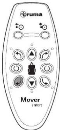
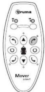
text_image
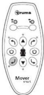
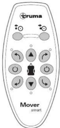
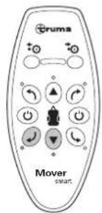
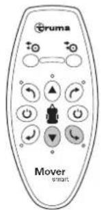
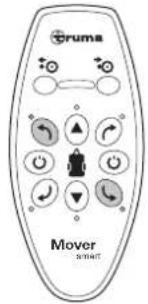
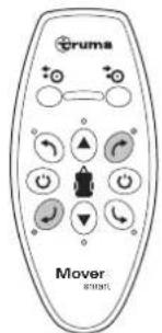
cruma Mover smartFig. 6
 | ONSwitch on (green button) |
 | OFFSwitch off (red button) / emergency stop switch |
 | LED display |
 | Engaging processDrive rollers engaged |
 | Disengaging processDrive rollers disengaged |
 | FORWARDDrive forward |
 | REVERSEDrive in reverse |
 | RIGHT FORWARDTurn in a clockwise direction when moving forwards |
 | RIGHT BACKTurn in an anti-clockwise direction when reversing |
 | LEFT FORWARDTurn in an anti-clockwise direction when moving forwards |
 | LEFT BACKTurn in a clockwise direction when reversing |
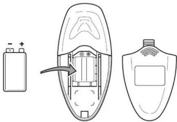
4.5.2 Replacing remote control batteries
NOTICE
Damage to the remote control due to leaking batteries
Leaking batteries can damage the remote control. Then, the manoeuvring system can no longer be used.
▶ Use leak-proof batteries.
▶ If the remote control is not being used for an extended period of time, remove the batteries from the remote control.
▶Different types of batteries or new and used batteries must not be used together.
▶ Flat batteries must be removed from the remote control and disposed of safely.
▶ Use only leak-proof 9 V batteries (MN 1604).
the red LEDs on the remote control flash when the battery is too weak.
natural_image
Diagram showing battery charging process with internal components and a separate device outline (no text or symbols)Fig. 7
▶Open the battery cover
▶Remove used batteries and insert new ones (pay attention to the positive and negative terminals)
▶Close the battery cover again
① warranty is given for damage caused by leaking batteries.
4.5.3 The remote control's automatic switch-off
The remote control switches itself off automatically after approx. 3 minutes if none of the buttons are pressed.
▶To reactivate the remote control, press the green ON button.
⑦here is no "On / Off" switch on the caravan itself.
4.5.4 Switching off the remote control (emergency stop)
▶Press the red OFF button ah the remote control. The LED indicator goes out
disposal of batteries is described in Kapitel 9.2.
5 Operation
Observe the safety instructions before using the manoeuvring system. See Kapitel 2

WARNING
Personal injury due to the caravan behaving in an uncontrolled manner.
If the drive rollers are not completely engaged, uncontrolled changes of direction or driving movements may occur during manoeuvring.
▶ Check that the engagement has been successful on both sides. See Kapitel 5.3

WARNING
Personal injury due to the caravan sliding in an uncontrolled manner.
The caravan's tyres may lose grip on slippery surfaces (snow, ice, slush, wet grass).
▶ Watch out for uncontrolled sliding movements.
▶ Keep a safe distance from the caravan.
NOTICE
Property damage due to a lack of care and maintenance performed on the manoeuv-ring system
If the manoeuvring system is not kept clean and regularly maintained, dirt and lack of control of the manoeuvring system and tyres can lead to damage.
▶ Inspect the manoeuvring system for damage before use.
▶ Check the tyre condition and pressure.
▶ Check the gap between the tyres and drive rollers.
▶ Remove any foreign bodies, dirt or similar items from between the drive rollers and tyres.
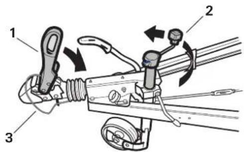
5.1 Uncoupling the towing vehicle
▶Secure the towing vehicle against rolling away. See the vehicle's operating instructions.

WARNING
Personal injury due to the caravan rolling away
Uncoupling the caravan from the towing vehicle can cause it to roll away in an uncontrolled manner.
▶ Apply the parking brake and/or secure the tyres with wedges (Fig. 8).
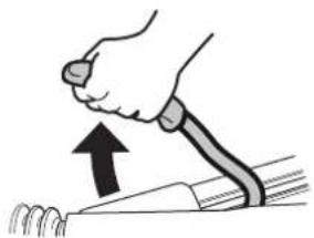
natural_image
Illustration of a hand gripping a tool with an upward arrow, no text or symbols presentFig. 8
▶Before uncoupling, make sure that the overrun brake is released.
text_image
Technical diagram of a mechanical linkage assembly with numbered componentsFig. 9
▶Remove the 13-pole plug or adapter from the vehicle
▶Release the breakaway cable (Fig. 9-1)
▶Crank out the jockey wheel until it makes contact with the ground (Fig. 9-2)
▶Open the drawbar coupling (Fig. 9-3) and lift with the jockey wheel (Fig. 9-4)
5.2 Switch on the manoeuvring system
5.2.1 Isolating switch

CAUTION
Personal injury due to activation of the battery cut-off switch when the drive rollers are engaged
The manoeuvring system can move off in an uncontrolled manner as soon as the power supply is established due to faulty wiring or a fault in the control unit.
▶ Only activate the battery cut-off switch when the drive rollers are disengaged
Procedure if there is a battery cut-off switch present:
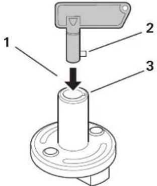
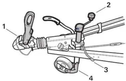
text_image
1 2 3Fig. 10
▶Insert the key into the battery cut-off switch (Fig. 10-1). Insert the lug (Fig. 10-2) into the recess (Fig. 10-3) while doing so.
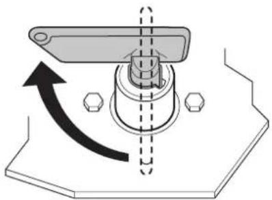
natural_image
Mechanical assembly diagram showing a rotating component with directional arrows (no text or symbols)Fig. 11
▶Turn the key. This establishes the power supply to the manoeuvring system.
5.2.2 Switch on the remote control
NOTICE
Property damage due to uncontrolled remote control button commands
If you put the switched-on remote control into your trouser pockets, or if it is used by children, the manouvring system can be set in motion unintentionally.
▶ Always switch off the remote control once manoeuvring is complete.
▶ Do not put the remote control into your trouser or similar pockets.
▶ Keep the remote control out of the reach of children.
text_image
Truma Mover smartFig. 12
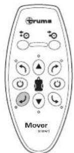
▶Press and hold the green ON button until the LED display lights up.
5.3 Engage the manoeuvring system

CAUTION
Personal injury due to the caravan rolling away
If the parking brake is released during the engagement, the caravan can roll away in an uncontrolled manner.
Only release the caravan's parking brake when the drive rollers on both sides are completely engaged.
The drive rollers are engaged on the caravan wheels by means of the remote control.
natural_image
Technical line drawing of a mechanical device with circular components and a gear-like component (no text or symbols)Fig. 13
▶Press and hold the ENGAGE button to engage the drive units.
After 5 seconds, the LED display flashes and engaging of the drive units starts.
The ENGAGE button can be released.
The LED display flashes during the engagement
At the end of the engagement, the drive rollers move back a few millimetres to relieve the strain on the mechanical system.
If the engagement is complete, the LED display stops flashing and continuously lights up green.
text_image
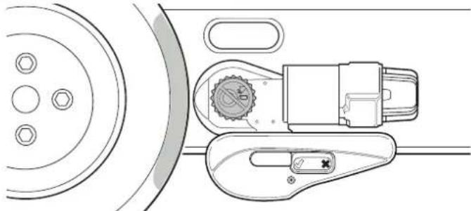
Technical diagram showing a mechanical device with a highlighted lever and a control panel labeled 'truma' with checkmark and cross icons.Fig. 14
natural_image
Technical line drawing of a mechanical device with a circular component and a clamped lever (no text or symbols)Fig. 15
To check that the engagement has been successful:
• The position indicator is set to √
- The drive rollers are pressed approx. 20 mm into the tyres on both sides.
If the drive units do not engage properly, see Kapitel 6 Malfunctions.
5.4 Manoeuvring the caravan

WARNING
Personal injury due to a lack of safety precautions
If persons or objects are present in the manoeuvring range during the manoeuvring, injuries may occur.
There must not be any people or objects in the manoeuvring range.
▶ Nobody may remain in or on the caravan.

CAUTION
Personal injury due to the manoeuvring system malfunctioning
Malfunctions in the manoeuvring system, the control unit or the remote control can lead to the caravan moving unpredictably.
The "Off" switch on the remote control can also be used as an emergency stop function in dangerous situations. Press the "Off" switch immediately if there are noticeable problems. See Kapitel 4.5.4
▶Apply the parking brake
▶Interruption of the battery cut-off switch

NOTICE
Damage to the tyres due to manoeuvring with the parking brake applied
If the caravan's parking brake is not released after the engagement, the tyres may be damaged when the caravan is manoeuvred.
▶ Before manoeuvring, release the parking brake or remove the chocks.
After starting up, the manoeuvring system moves at a steady speed. Speed increases slightly on downhill slopes and decreases on uphill slopes.
System factors mean that the speed increases on slopes. You can reduce the speed by stopping and restarting the caravan several times.
When the buttons are released, or if the radio signal is interrupted or becomes too weak, the caravan immediately stops moving.
▶ Use the direction buttons to move the caravan in the required direction:
Forward
text_image
Truma Mover 301041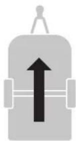
natural_image
Simple gray icon of a device with an upward arrow and handle (no text or symbols)Fig. 16
▶Backward
text_image
Cruma Mover START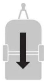
natural_image
Simple gray icon of a device with a downward arrow, no text or symbols presentFig. 17
The direction buttons can be used to turn the caravan:
▶ Left (forward)
text_image
Gruma Mover smart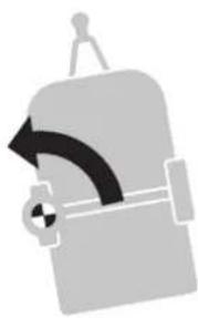
natural_image
Silhouette of a device with a curved arrow and circular button, no text or symbols presentFig. 18
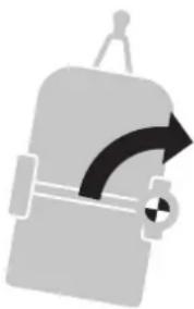
▶Right (forward)
text_image
Gruma Mover START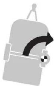
natural_image
Simple gray icon of a device with a curved arrow and circular button (no text or symbols)Fig. 19
▶ Left (reverse)
text_image
Grums Mover sound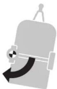
natural_image
Silhouette of a person holding a device with a curved arrow, no text or symbols presentFig. 20
▶Right (reverse)
text_image
Eruma Mover smart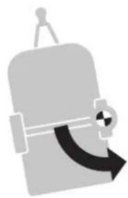
natural_image
Simple gray icon of a device with a curved arrow, no text or symbols presentFig. 21
When driving (forwards / in reverse), the driving direction can be adjusted by pressing the direction buttons at the same time:
▶Forward (turning left)
text_image
Cruma Mover 301941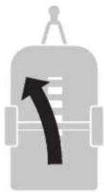
natural_image
Simple gray icon of a device with a curved arrow indicating direction (no text or symbols)Fig. 22
natural_image
Simple gray icon of a device with a black arrow pointing upward, no text or symbols present.Fig. 23
▶Reverse (turning left)
text_image
Gruma Mover smart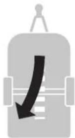
natural_image
Simple gray icon of a container with a downward arrow, no text or symbols presentFig. 24
▶Reverse (turning right)
text_image
Gruma Mover smart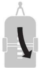
natural_image
Simple gray icon of a container with a curved arrow pointing downward (no text or symbols)Fig. 25
If the opposite direction buttons are pressed at the same time, the caravan rotates on the spot in the direction in question:
text_image
Truma Mover SUPPORT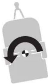
natural_image
Simple gray icon of a device with a curved arrow and circular button, no text or symbols present.Fig. 26
text_image
Cruma Mover STRAW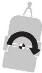
natural_image
Abstract gray icon of a container with a curved arrow and circular pattern inside, no text or symbols present.Fig. 27
Radio equipment or other remote controls will not activate your manoeuvring system.
▶After manoeuvring, apply the parking brake and/or secure the caravan with chocks to prevent it from rolling away first of all, then deactivate the manoeuvring system.
5.5 Coupling to the towing vehicle
The manoeuvring system allows a caravan to be coupled to a towing vehicle accurately and without jolting. However, this requires care and a degree of practice.
▶Move the towing vehicle close to the caravan.
▶Secure the towing vehicle against rolling away according to the operating instructions.
In order to position the caravan precisely, use the direction buttons of the remote control until the
caravan's coupling is directly above the ball coupling on the towing vehicle.
text_image
Technical diagram of a mechanical linkage system with numbered components and directional arrows indicating motion or assembly.Fig. 28
▶Coupling the caravan on the ball coupling (Fig. 28-1)
▶Crank in the jockey wheel and secure it according to the operating instructions (Fig. 28-2)
▶ Attach the breakaway cable (Fig. 28-3)
▶Then disengage the manoeuvring system. See Kapitel 5.6
Insert the 13-pole plug or adapter into the towing vehicle's 13-pole supply socket.
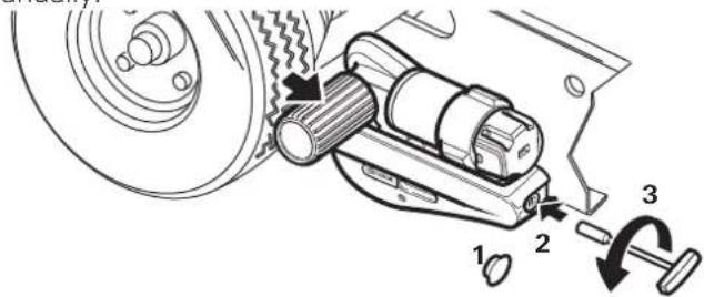
5.6 Disengage the manoeuvring system
NOTICE
Property damage due to towing with the drive rollers engaged
If the caravan is being towed by the towing vehicle with the drive rollers engaged, the manoeuvring system, the towing vehicle or even the caravan can be damaged.
▶ Ensure that the drive rollers are completely disengaged before the caravan is towed by the towing vehicle.

CAUTION
Personal injury due to the caravan rolling away
If the drive rollers are disengaged, the caravan cannot be controlled.
Before the disengagement, apply the caravan's parking brake and/or secure the caravan with wedges.
The manoeuvring system can also be disengaged manually if the power supply of the manoeuvring system is interrupted or if a malfunction prevents automatic disengagement. See Kapitel 5.7 Emergency disengagement.
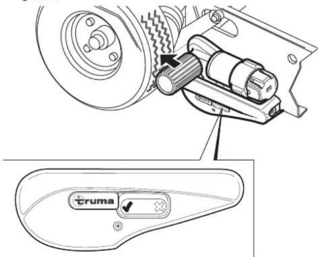
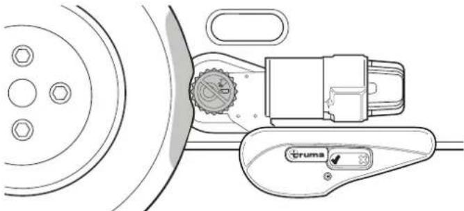
▶Press and hold the DISENGAGE button for approx. 5 seconds. Then release. The drive roller disengages. The LED display flashes during the disengagement.
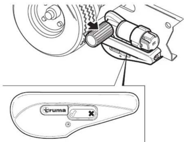
text_image
Technical diagram showing a mechanical device with a highlighted lever and a control panel labeled 'truma' with a checkmark and cross.Fig. 29
the procedure is completed only when the display on the remote control stops flashing. The remote control can now send new commands or be switched off.
① not switch the remote control off while the display is flashing. Otherwise, this interruption of the process can lead a renewed automatic engagement being impossible. In this case, the Mover smart A sometimes has to be engaged manually before the next engagement. See Kapitel 6.1.
text_image
Technical diagram of a mechanical assembly with numbered components and directional arrows indicating motion or assembly steps.Fig. 30
▶Remove the cover (Fig. 30-1) on the rear of the Mover smart A.
Insert the hexagonal socket spanner into the opening (Fig. 30-2) and carefully turn it approx. two turns in a clockwise direction (Fig. 30-3) until the Mover smart A is engaged a little.
▶ Afterwards, the Mover smart A can be engaged automatically again.
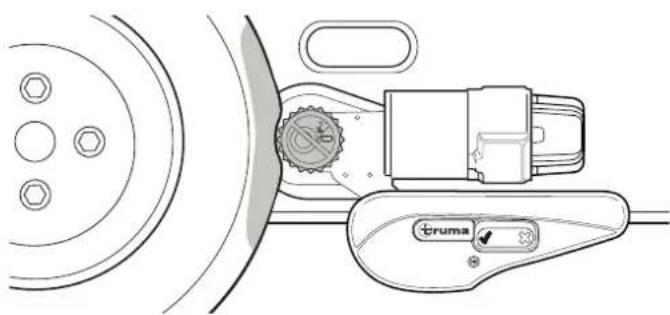
To check that the disengagement has been successful:
- The LED display stops flashing and continuously lights up green.
- At the end of the process, the drive rollers move forward again a few millimetres to relieve the strain on the mechanical system. The drive rollers are not in contact with the tyres.
• ✗ is visible on the Mover smart A. - The gap between the drive rollers and the tyres is approx. 20 mm on both sides.
natural_image
Technical line drawing of a mechanical assembly with circular components and a gear-like component (no text or symbols)Fig. 31
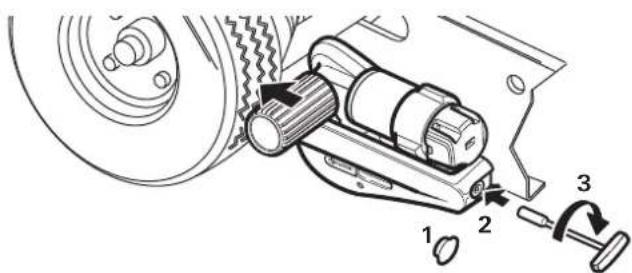
5.7 Disengage the manoeuvring system manually (emergency disengagement)

CAUTION
Personal injury due to the caravan rolling away
If the drive rollers are disengaged, the caravan cannot be controlled.
Before the disengagement, apply the caravan's parking brake and secure with wedges.

NOTICE
Damage due to an incorrect tool
The manoeuvring system must only be disengaged manually. Other auxiliary equipment, e.g. cordless screwdrivers, can damage the manoeuvring system.
▶ Use the supplied hexagonal socket spanner.
If the caravan battery is discharged to the extent that electrical disengagement no longer works or a defect is present, the drive rollers can also be disengaged manually.
text_image
Technical diagram of a mechanical device with numbered components and directional arrows indicating motion or assembly.Fig. 32
Before manual disengagement, apply the caravan's parking brake and secure the wheels against rolling away.
▶Disconnect the power supply for the Mover smart A using the battery cut-off switch.
Remove the cover (Fig. 32-1) on the rear of the Mover smart A.
Insert the hexagonal socket spanner into the opening (Fig. 32-2) and carefully turn it in an anti-clockwise direction (Fig. 32-3) until the Mover smart A is completely disengaged.
▶ Repeat the procedure for all drive units
Once the battery has been charged or the defect remedied, the drive rollers can be engaged electrically again.
5.8 Switch off the manoeuvring system
NOTICE
Damage to the tyres and drive unit due to continuously engaged drive rollers.
If the manoeuvring system's drive rollers remain engaged continuously, this can cause damage to tyres and drive units if the system is at a standstill for an extended period of time.
The drive rollers must be fully disengaged if the system is at a standstill for an extended period of time.
5.8.1 Switch off the remote control
▶Press the red OFF button ☑ the remote control.
text_image
cruma Mover smartFig. 33
5.8.2 Battery cut-off switch
▶Depending on the installation in the caravan, also disconnect the power supply for the manoeuvring system using the battery cut-off switch.
natural_image
Mechanical assembly diagram showing a rotating shaft and housing with a curved arrow indicating motion (no text or symbols)Fig. 34
▶Turn the key in an anti-clockwise direction. This interrupts the power supply to the manoeuvring system.
Remove the key of the battery cut-off switch and keep it in a safe place that is inaccessible to children.
6 Malfunctions
6.1 Troubleshooting guide
▶Before contacting Customer Service:
- Check whether the batteries in the remote control are working perfectly.
- Is the remote control paired with the control unit?
Pairing the electronic control unit with the radio remote control see Kapitel 6.2.
▶Check that the caravan battery is in good condition and is fully charged.
Battery performance can deteriorate considerably at cold ambient temperatures.
▶Check that the fuse in the battery connector cable is in order. If the fuse is defective, check the system for possible short circuits.
ferrors occur, the remote control always switches off once the symbols have been shown.
| Malfunction Cause and remedy | |
| Manoeuvring system not working | Check the power supply (the green LED on the control unit must be lit). Replace a defective fuse in the battery connection cable of the manoeuvring system only with an original Truma spare part (part no. 60040-00169).Interrupt the power supply for at least 20 seconds. Restore the power supply. The green LED on the control unit should be lit. |
| Manoeuvring system not working and red LED on control unit flashing | Control unit is overheated.Interrupt the power supply with the battery cut-off switch and remove the key. Allow the control unit to cool down for at least 20 minutes. Then start the manoeuvring system. |
| Malfunction Cause and remedy | |
| Manoeuvring system not re-sponding to commands from remote control or only with interruptions | Weak battery in the remote con-trol – red LEDs on the remote control flashing.Check the battery and bat-tery contacts of the remote control. Replace battery and/or clean battery contacts if necessary. |
| Manoeuvring system’s battery low – green LED on control unit flashes.Check the manoeuvring system’s battery. Charge or replace battery if necessary. | |
| Drive roller sliding off tyre | Check tyre pressure and ad-just if necessary.Check tread and replace tyres if necessary.Disengage the manoeuvring system and measure the gap between the tyres and drive roller. The gap must be 20 mm. |
| Manoeuvring system not en-gaging on one side or on both sides | Turn the hexagonal socket spanner clockwise approx. 2 turns to slightly engage the Mover smart A. Then try en-gaging again. See Kapitel 5.6Make sure that the power supply is not interrupted and that the remote control is not switched off during disenga-ging. During the disengage-ment, when the drive rollers have completely disengaged, they again move forward a few millimetres to take the load off the mechanics. The procedure is completed only when the display on the re-mote control stops flashing. |
| Manoeuvring system not disengaging | Disengage the manoeuvring system manually (see Kapitel 5.7) |
▶If these actions do not remedy the problem, please contact Truma Service.
6.2 Pairing the electronic control unit with the radio remote control
The remote control and the control unit are paired in the factory.
If the control unit or the remote control is replaced, they must be paired again.
▶The drive rollers must not be engaged
Check that the battery is properly connected and in good condition, and that the control unit is being supplied with 12 V.
Procedure:
text_image
3 2 1 (0,0) Mover powerFig. 35
▶Establish the power supply via the battery cut-off switch. Green LED (Fig. 35-2) lit.
▶Press the reset button (Fig. 35-1) on the remote control with a thin object. The antenna of the control unit can be used for this.
The green and red LEDs (Fig. 35-3) on the remote control now flash alternately.
▶Then switch on the remote control. To do this, press the green ON button .
The control unit and remote control pair automatically. The green LED on the control unit lights up.
7 Care and maintenance

RISK
Severe to lethal injury due to short circuiting
Parts of the appliance are supplied with power over an on-board power supply consisting of 12 V batteries. In the event of high electrical loads or a short circuit, very high currents can flow through the supply lines, causing the cables to heat up and a cable fire to break out.
▶ Fuse cables with appropriate safety fuses.
▶ Cover the battery terminals.
▶ Cover open electrical contacts.
▶ Use isolated plug-in connectors.
NOTICE
Damage to the manoeuvring system due to incorrect cleaning
▶ Do not clean the manoeuvring system with a high-pressure cleaner.
▶ Only use gentle detergents.
Cleaning and user-performed maintenance must not be carried out by children when unsupervised.
7.1 12 V battery care
Notes for handling batteries
When handling batteries, pay attention to the manufacturer's safety instructions and data sheets.
▶ Ensure that the terminal clamps are secure.
▶Secure battery poles with protection caps in order to prevent a short circuit
When removing the battery, first disconnect the earth connection (negative terminal), followed by the positive terminal.
When installing the battery, first connect the positive terminal followed by the negative terminal.
Battery care (including maintenance-free batteries)
In order to achieve a long battery service life, attention must be paid to the following points:
▶Batteries should be fully charged before and after removing power.
For stationary periods of longer than 24 hours, interrupt the power circuit (e.g. using the battery cut-off switch or by disconnecting the battery poles).
For longer stationary periods the battery must be disconnected and charged for 24 hours at least every 12 weeks.
i winter, store the fully-charged battery in a cool and frost-free place and recharge at regular intervals (every 12 weeks).
7.2 Remote control care
▶The remote control must be kept in a dry place.
Remove the remote control's batteries during extended stationary periods (e.g. in winter) to prevent the batteries from going flat.
Before use and before engagement, check that all motors respond properly to the commands from the remote control.
7.3 Tyre care
▶Do not park the caravan with engaged drive rollers, otherwise the tyres could be damaged.
7.4 Drive unit care
the drive units must be able to move freely and be returned automatically to the safe idle position when they are disengaged.
If this is not the case, check the drive units for dirt or corrosion on their guides and clean them if necessary to ensure they can move properly.
When cleaning the caravan, hose off the manoeuvring system and clean with a soft brush. Make sure that no stones, twigs etc. are trapped in it.
7.5 Maintaining the manoeuvring system

RISK
Personal injury due to a lack of system maintenance
If the gap between the drive rollers and tyres is too large or if the tyre pressure is too low, there is a risk that the drive rollers will no longer engage completely with the necessary pressure.
▶ Regularly check the gap between the drive rollers and tyres using the spacer plate.
- Regularly check the caravan's tyres and the tyre pressure.
At least every 2 years, have an expert check that there is no rust on the manoeuvring system, that the attachments are still firmly attached and that all the safety-related parts are in a proper condition.
the manoeuvring system is extremely easy to check or maintain during the caravan's annual inspection. If in doubt, please contact Truma Service (www.truma.com).
7.6 Maintaining the tyres
Before use, check the tyre pressure and that the drive rollers have the correct gap to the tyres when disengaged.
▶ Every time tyres are replaced, check the gap between the drive rollers and the tyres and, if necessary, have it adjusted by a specialist shop.
7.7 Maintaining the control unit
The control unit does not require any maintenance
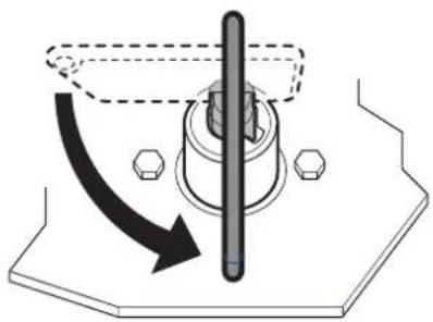
7.8 Check the gap between the rollers and the tyres
The gap between the tyres and drive rollers can be checked using the spacer plate. The gap should be 20 +/- 1 mm.
▶The manoeuvring system must be disengaged.
▶Slide the spacer plate between the tyre and drive the roller.
The spacer plate may just fit between the tyre and the drive roller. If the spacer has too much play and falls through between the tyre and the drive roller, the gap must be readjusted.
▶If the gap is larger, have it corrected by a specialist shop.
7.9 Standstill for an extended period of time
▶Clean the manoeuvring system as described above every year (or before preparing for winter).
▶To prevent the battery from becoming totally discharged during long periods of inactivity, it must be disconnected and then recharged from time to time. Charge the caravan battery before starting up.
8 Repair
NOTICE
Damage due to repair work being carried out by incompetent individuals
If the manoeuvring system is damaged, further damage may result if untrained individuals perform the repair work or genuine Truma spare parts are not used.
▶ Only have experts perform repair work on the manoeuvring system.
▶ Use only original Truma spare parts.
9 Disposal and recycling
9.1 Disposing of the manoeuvring system

RISK
Risk of injury due to the weight of the entyre system
There is a risk of injury when transporting the dismantled manoeuvring system due to the weight.
▶ Bear the weight of the entyre system in mind.

RISK
Risk of injury due to heavy attachments
Risk of severe injury when transporting the dismantled manoeuvring system due to heavy attachments.
▶ Do not carry heavy attachments on your own.
The device must be disposed of in accordance with the administrative regulations of the respective country in which it is used. National regulations and laws must be observed.
9.2 Disposing of remote control and batteries

Neither the remote control nor the batteries may be disposed of with domestic waste; instead they must be taken to a collection point for recycling.
By doing this you are contributing towards reuse and recycling.
10 Technical data
| Designation Mover smart A | |
| Range of use | Single-axle caravans with a gross weight of up to 2000 kg |
| Max. climbing ability | 13 % |
| Operating voltage | 12 V AC/DC |
| Maximum power consumption | 125 A |
| Average power consumption | 35 A |
| Quiescent current Inserted plug or adapter Removed plug or adapter | 60 mA(30 mA) |
| Maximum speed | 0,15 m/s |
| Weight (not including battery) | 32 kg |
| Remote control frequency | Class 1, 868 MHz |
| Remote control battery | 9 V battery (MN 1604) |
11 Warranty
Manufacturer's Warranty (European Union)
11.1 Scope of Manufacturer's Warranty
As the Manufacturer of the appliance referred to in these operating instructions, Truma grants the Consumer a warranty that covers any material and/or manufacturing defects of the appliance.
This Manufacturer's Warranty is applicable in the EU member states as well as in the United Kingdom, Iceland, Norway, Switzerland and Turkey.
This Manufacturer's Warranty covers any of the aforementioned defects that occur within 24 months upon concluding the purchase agreement between the Seller and the Consumer. A Consumer is the natural person who was the first one to purchase the appliance from the Manufacturer, OEM or dealer and who neither resold the appliance in a commercial or self-employed professional capacity nor installed it for a third party in such a capacity.
The Manufacturer or an authorised service partner undertakes to remedy such defects through subsequent fulfilment, i.e. at its discretion either by repairing or replacing the defective item, unless one of the reasons for exclusion mentioned below applies. Defective or exchanged parts or appliances shall become the property of the Manufacturer or the authorised service partner. If the appliance is no longer manufactured at the time of defect notification and if replacement delivery has been opted for, then the Manufacturer may deliver a similar product.
If the Manufacturer remedies a defect under this Manufacturer's Warranty, the term of the Warranty shall not start again with regard to the repaired or exchanged parts; rather, the original warranty period shall continue to be applicable to the appliance. Only the Manufacturer itself or an authorised service partner shall be entitled to conduct a warranty job. Any costs that occur in the event of a warranty claim shall be settled directly between the authorised service partner and the Manufacturer. The Warranty does not cover additional costs arising from complicated removal or installation jobs on the appliance (e.g. dismantling of furnishings or parts of the vehicle body), and neither does it cover travel expenses incurred by the authorised service partner or the Manufacturer.
Further claims arising from this Manufacturer's Warranty, in particular claims for damages by the Consumer or third parties, are excluded. This shall not affect the provisions of the German Product Liability Act (Produkthaftungsgesetz).
The legal warranty claims for defects of the Consumer against the Seller in the respective country of purchase are not limited by this Warranty and may be asserted free of charge independently of this Warranty. In countries outside the European Union, these statutory warranty claims are governed by the regulations of the country in which the Consumer first purchased the appliance.
In individual countries there may be warranties that can be issued by the relevant dealer (official distributor, Truma Partner). In such cases the warranty can be implemented directly through the dealer from whom the Consumer bought the appliance. The warranty regulations of the country in which the appliance was purchased by the Consumer for the first time shall also be applicable.
11.2 Exclusion of warranty
No warranty claims from this Manufacturer's Warranty shall be applicable under the following circumstances:
- Improper, unsuitable, faulty, negligent or unintended use or handling of the appliance;
- Improper installation, assembly or commissioning, contrary to operating or installation instructions;
- Improper operation, handling or operation contrary to the operating and installation instructions, particularly any disregard for maintenance, care and warning notes, or the operation of defective appliances.
- Instances where installations, repairs or any other procedures are carried out by non-authorised partners or on the user's own initiative;
- Consumable materials and parts which are subject to natural wear and tear;
- If the appliance is fitted with spare, supplementary or accessory parts that are not original parts from the Manufacturer or have not been approved by the Manufacturer; this applies in particular if the appliance is subject to networked control, if the control units or the software have not been approved by Truma or if the Truma control unit (e.g. Truma CP plus, Truma iNetBox, Truma iNet X Pro Panel, Truma iNet X Panel, or similar) has not been exclusively used for controlling Truma appliances or appliances approved by Truma;
- As a consequence of damage arising from foreign substances (e.g. oil, or plasticisers in the gas), chemical or electrochemical influences in the water, or cases when the appliance has come into contact with unsuitable substances (e.g. chemical products, flammable substances or unsuitable cleaning agents);
- Damage caused by abnormal environmental or unsuitable operating conditions;
-
Damage caused by force majeure or natural disasters or any other influences not within Truma's responsibility;
• Damage resulting from improper transport; -
End customer's or third-party modifications of the appliance, including any replacement, supplementary or accessory parts, or installation of the same, especially concerning the exhaust gas system or the cowl;
- As a consequence of intentional or negligent damage.
11.3 Making a warranty claim
The name and address of the Manufacturer and guarantor is:
85640 Putzbrunn, Germany
The warranty must be claimed with an authorised service partner or at the Truma Service Centre. All the relevant addresses and phone numbers can be found at www.truma.com, in the “Service” section.
To ensure a smooth procedure, we would be grateful if you could have the following details ready before contacting us:
• Detailed description of the defect
- Serial number of the appliance
- Date of purchase
The authorised service partner or the Truma Service Centre will then specify the further procedure. To avoid transport damage, the affected appliance must only be shipped by prior arrangement with the authorised service partner or the Truma Service Centre. We ask you not to send in an appliance without prior arrangement.
If the warranty claim is recognised by the Manufacturer, then the transport expenses shall be borne by the same. If no warranty claim is applicable, the Consumer will be notified accordingly and any repair and transport expenses shall then be the Consumer's liability.
Table des matières
text_image
Technical diagram of a vehicle-mounted industrial machine with numbered components and signal propagation indicatorsFig. 1
text_image
Technical diagram of a mechanical device with numbered parts labeled 1 to 4Fig. 2
text_image
Technical diagram showing two mechanical assembly components labeled 1 and 2, with numbered parts and cross-sectional views.Fig. 4
natural_image
Line drawing of a rectangular electronic device with wires and ports, no text or symbols presentFig. 5
4.5 Télécommande
text_image
Diagram showing battery charging process with labeled components and directional arrow indicating charging directionFig. 7
natural_image
Illustration of a hand gripping a tool with an upward arrow, no text or symbols presentFig. 8
text_image
Technical diagram of a mechanical linkage system with numbered componentsFig. 9
natural_image
Mechanical component diagram showing a lever mechanism with rotation arrow and hexagonal base (no text or symbols)Fig. 11
natural_image
Technical line drawing of a mechanical device with circular components and a gear-like component (no text or symbols)Fig. 13
text_image
Technical diagram showing a mechanical assembly with a truma control panel and a directional arrow indicating motion or movement.Fig. 14
natural_image
Technical line drawing of a mechanical device with a circular component and a curved handle (no text or symbols)Fig. 15
natural_image
Simple gray icon of a device with an upward arrow and handle (no text or symbols)natural_image
Simple gray icon of a device with a downward arrow, no text or symbols presentFig. 17
natural_image
Silhouette of a medical device with a curved arrow indicating left motion (no text or symbols)natural_image
Gray icon of a device with a curved arrow, no text or symbols presentnatural_image
Silhouette of a person pushing a large object with a curved arrow, no text or symbols presentnatural_image
Simple gray icon of a briefcase with a curved arrow, no text or symbols presentnatural_image
Simple gray icon of a suitcase with an arrow indicating clockwise direction (no text or symbols)natural_image
Simple gray icon of a vehicle or container with an upward arrow, no text or symbols present.natural_image
Simple gray icon of a container with a downward arrow, no text or symbols presentnatural_image
Simple gray icon of a container with a black curved arrow pointing downward (no text or symbols)Fig. 25
natural_image
Abstract diagram of a stylized object with a curved arrow and circular element, no text or symbols presentFig. 26
text_image
Truma Mover screw1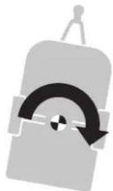
natural_image
Simple gray icon of a device with a curved arrow and circular element, no text or symbols present.Fig. 27
text_image
Technical diagram of a mechanical linkage system with numbered components and directional arrows indicating motion or movement.Fig. 28
text_image
Technical diagram showing a mechanical device with labeled components and a control panel labeled 'truma' with checkmark and cross icons.Fig. 29
text_image
Technical diagram of a mechanical device with numbered components and directional arrows indicating motion or assembly.Fig. 30
natural_image
Technical line drawing of a mechanical device with circular components and a belt switch (no text or symbols)Fig. 31
text_image
Technical diagram of a mechanical device with numbered components and directional arrows indicating motion or assembly.Fig. 32
natural_image
Mechanical assembly diagram showing a rotating shaft and nut assembly (no text or symbols)Fig. 34
text_image
Technical diagram of a vehicle's internal components with numbered parts labeled 1 through 7Fig. 1
text_image
Technical diagram of a mechanical device with numbered parts labeled 1 to 4Fig. 2
text_image
Technical diagram showing two mechanical components labeled 1 and 2, with arrows indicating assembly or movement.Fig. 4
natural_image
Line drawing of an electrical component with wires and connectors (no text or symbols)Fig. 5
4.5 Telecomando
text_image
Diagram showing battery polarity, internal structure, and device layout with signal iconsFig. 7
natural_image
Illustration of a hand gripping a tool with an upward arrow, no text or symbols presentFig. 8
text_image
Technical diagram of a mechanical linkage assembly with numbered componentsFig. 9
natural_image
Mechanical assembly diagram showing a rotating component with arrows indicating motion (no text or symbols)Fig. 11
natural_image
Technical line drawing of a mechanical device with circular components and a gear-like component (no text or symbols)Fig. 13
text_image
Technical diagram showing a mechanical assembly with a truma control panel and a directional arrow indicating motion.Fig. 14

natural_image
Technical line drawing of a mechanical device with a circular component and a curved handle (no text or symbols)Fig. 15
natural_image
Simple gray icon of a device with an upward arrow, no text or symbols presentFig. 16
Indietro
text_image
ruma Mover 40.541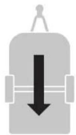
natural_image
Simple gray icon of a device with a downward arrow, no text or symbols presentFig. 17
natural_image
Silhouette of a device with a curved arrow indicating rotation or movement (no text or symbols)natural_image
Silhouette of a device with a curved arrow and circular button, no text or symbols presentnatural_image
Silhouette of a briefcase with a curved arrow indicating rotation or movement (no text or symbols)natural_image
Simple gray icon of a device with a curved arrow, no text or symbols presentFig. 21
natural_image
Simple gray icon of a device with a curved arrow, no text or symbols presentnatural_image
Simple gray icon of a container with a curved arrow and horizontal lines, no text or symbols present.natural_image
Simple gray icon of a container with a downward arrow, no text or symbols presentnatural_image
Simple gray icon of a container with a black curved arrow pointing downward (no text or symbols)Fig. 25
natural_image
Simple gray icon of a device with a curved arrow and circular element, no text or symbols present.Fig. 26
text_image
Gruma Mover setout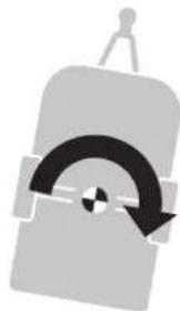
natural_image
Simple gray icon of a device with a curved arrow and circular button, no text or symbols present.Fig. 27
text_image
Technical diagram of a mechanical device with numbered components and directional arrows indicating motion or assembly.Fig. 28
text_image
Technical diagram showing a mechanical device with a labeled control panel 'truma' and a warning arrow indicating action.Fig. 29
text_image
Technical diagram of a mechanical device with numbered components and directional arrows indicating motion or assembly.Fig. 30
natural_image
Technical line drawing of a mechanical device with circular components and a gear-like component (no text or symbols)Fig. 31
text_image
Technical diagram of a mechanical device with labeled parts and directional arrows indicating motion or assembly.Fig. 32
natural_image
Mechanical assembly diagram showing a rotating shaft and housing with a curved arrow indicating motion (no text or symbols)Fig. 34
EU Declaration of Conformity
(The product is in conformity with the relevant Union harmonisation legislation):
(Machinery Directive)
(Radio Equipment Directive)
(The following (harmonised) standards and other technical specifications were used):
ETSI EN 300 220-1 V3.1.1; ETSI EN 300 220-2 V3.1.1
Entwurf (Draft) ETSI EN 301 489-1 V2.2.0;
Entwurf (Final Draft) EN 301 489-3 V2.1.1
EN 62479:2010
EN 62368-1:2014+A11:2017
EN ISO 12100:2010
(The VGA, Bristol BS5 6XX, United Kingdom issued the type approval(s)):
E11 10R-05 10956
(Signed for and on behalf of):
(Managing Director Technical) Putzbrunn, 25.03.2022
EN Should problems occur, please contact the Truma Service Centre or one of our authorised service partners (see www.truma.com).
In order to avoid delays, please have the unit model and serial number ready (see type plate).