
FM 1000 - Milling machine Mafell - Free user manual and instructions
Find the device manual for free FM 1000 Mafell in PDF.
| Product Type | Milling motor for fixed mounting on gantry |
| Brand | Mafell |
| Model | FM 1000 |
| Dimensions (L x W x H) | 73 x 254 x 79 mm (versions FM 1000, FM 1000 PV, FM 1000 PV-ER) ; 92 x 280 x 85 mm (versions FM 1000 WS, FM 1000 PV-WS) |
| Weight | 1.6 kg (FM 1000, FM 1000 PV, FM 1000 PV-ER, FM 1000 120 V) ; 2.8 kg (FM 1000 WS, FM 1000 PV-WS) |
| Rated voltage | 230 V (230 V versions) ; 120 V (120 V version) |
| Mains frequency | 50 Hz (230 V) ; 60 Hz (120 V) |
| Power consumption | 1000 W |
| Rated current | 4.6 A (230 V) ; 8.3 A (120 V) |
| No-load speed range | 4000 - 25000 min⁻¹ (except FM 800: 7000-25000, FM 1000 120 V: 10000-25000) |
| Tool holder | Collet chuck Ø 8 mm (standard); admissible tool shank 3-8 mm |
| Max. cutter diameter | 36 mm |
| Max. grinding wheel diameter | 40 mm |
| Mains cable length | 4 m (except FM 800: 1 m, PV versions: 0.75 + 4 m) |
| Protection class | II (double insulation) |
| Sound pressure level (LPA) | 71 dB(A) (no load, without tool) |
| Sound power level (LWA) | 82 dB(A) (no load, without tool) |
| Overload protection | Dynamic monitoring of current, speed and temperature; shutdown with red indicator |
| PV variant | Interface for gantry with external speed control (0-10 V) and remaining operating time output |
| Maintenance | Replace carbon brushes every 125-150 hours; clean regularly; lubricate collets |
| Supplied accessories | Operating instructions, 17 or 25 mm spanner, collet chuck OZ8 Ø 8 mm, mains cable; cap Z for PV versions |
| Intended use | Fixed mounting in a gantry system; not for continuous industrial use |
| Country of manufacture | Germany |
Frequently Asked Questions - FM 1000 Mafell
User questions about FM 1000 Mafell
0 question about this device. Answer the ones you know or ask your own.
Ask a new question about this device
Download the instructions for your Milling machine in PDF format for free! Find your manual FM 1000 - Mafell and take your electronic device back in hand. On this page are published all the documents necessary for the use of your device. FM 1000 by Mafell.
USER MANUAL FM 1000 Mafell
Please read all safety instructions and directions. Failure to comply with the safety instructions and directions can cause electric shock, fire and/or serious injuries. Please retain all safety instructions and directions for future reference.
AVERTISSEMENT
GB - EC - Declaration of Incorporation
We herewith certify that the milling motor FM 800/1000 WS/PV/ER complies with the specified EU directives. Before initial operation of the milling motor, the operating company must ensure that the combination of incomplete machine (FM) and customised machine complies with the requirements of the currently valid directives. Authorised person for the compilation of the technical documentation for the incomplete machine: Mafell AG
9M0001, 9M0020, 9M0021, 9M0023
9M0201, 9M0223
9M0401, 9M0423
9M0101
9M0301, 9M0323
1 Signs and symbols 22
2 Product information 22
2.1 Manufacturer's data 22
2.2 Machine identification 22
2.3 Technical data 23
2.4 Emissions 23
2.5 Scope of supply 24
2.6 Use according to intended purpose 24
2.7 Residual risks 24
3 Safety instructions 25
4 Setting/Adjustment 26
4.1 Mains connection 26
4.2 Selection of tools 26
4.3 Tool change 26
4.4 Collets 27
5 Operation 27
5.1 Initial operation 27
5.2 PV design 28
5.3 Speed specification 29
5.4 Overload protection 30
6 Service and maintenance 31
6.1 Storage 31
7 Troubleshooting 32
8 Optional accessories 33
9 Exploded drawing and spare parts list 33
1 Signs and symbols

This symbol is found in all places where you will find information for your safety.
Non-compliance with these instructions may result in very serious injuries.

This symbol indicates a potentially hazardous situation.
If this situation is not avoided, the product or objects in its vicinity may get damaged.

This symbol indicates tips for the user and other useful information.
2 Product information
Model
FM800
FM 1000
FM 1000 PV
FM 1000 PV-ER
FM 1000 WS
FM 1000 PV-WS
Art.-No.
9M0010, 9M0030, 9M0031
9M0001, 9M0020, 9M0021, 9M0023
9M0201, 9M0223
9M0401, 9M0423
9M0101
9M0301, 9M0323
2.1 Manufacturer's data
MAFELL AG, Beffendorfer Straße 4, D-78727 Oberndorf / Neckar, Phone +49 (0)7423/812-0, Fax +49 (0)7423/812-218, e-mail: mafell@mafell.de
2.2 Machine identification
All details required for machine identification are available on the attached rating plate.

Protection class II

CE symbol to document compliance with the basic safety and health requirements according to Appendix I of the Machinery Directive.

For EU countries only
Do not dispose of milling motors together with domestic waste!
In accordance with the European directive 2002/96/EC on waste electrical and electronic equipment and transposition into national law, obsolete milling motors must be collected separately and recycled in an environmentally-compatible manner.

To reduce the risk of injury, please read the operating instructions.
2.3 Technical data
| FM 800 | FM 1000 | FM 1000 PV | FM 1000 PV-ER | FM 1000 WS | FM 1000 PV-WS | FM 1000 (120 V) | |
| Operating voltage / V | 230 | 230 | 230 | 230 | 230 | 230 | 120 |
| Mains frequency / Hz | 50 | 50 | 50 | 50 | 50 | 50 | 60 |
| Input power / W | 800 | 1000 | 1000 | 1000 | 1000 | 1000 | 1000 |
| Nominal current / A | 4.0 | 4.6 | 4.6 | 4.6 | 4.6 | 4.6 | 8.3 |
| Supply voltage / V* | - | - | 8 - 56 | 8 - 56 | - | 8 - 56 | - |
| Control voltage for speed specification / V* | - | - | 0 - 10 | 0 - 10 | - | 0 - 10 | - |
| Display remaining runtime / V* | - | - | 0 - 5 | 0 - 5 | - | 0 - 5 | - |
| Power consumption / mA* | - | - | 3 - 5 | 3 - 5 | - | 3 - 5 | - |
| Idling speed / rpm | 7000 - 25000 | 4000 - 25000 | 4000 - 25000 | 4000 - 25000 | 4000 - 25000 | 4000 - 25000 | 10000 - 25000 |
| Tool holding fixture with collet ø / mm | 6 | 8 | 8 | 8 | 8 | 8 | 6.35 (1/4") |
| Tool shank / mm | 3 - 8 | 3 - 8 | 3 - 8 | 3 - 8 | 3 - 8 | 3 - 8 | 3 - 8 |
| Milling cutter ø, max. / mm | 36 | 36 | 36 | 36 | 36 | 36 | 36 |
| Grinding tool ø, max. / mm | 40 | 40 | 40 | 40 | 40 | 40 | 40 |
| Weight without mains cable / kg | 1.6 | 1.6 | 1.6 | 1.6 | 2.8 | 2.8 | 1.6 |
| Length of connecting cable / m | 1 | 4 | 0.75 + 4 | 0.75 + 4 | 4 | 0.75 + 4 | 4 |
| Dimensions (W x L x H) / mm | 73 x 254 x 79 | 73 x 254 x 79 | 73 x 254 x 79 | 73 x 254 x 79 | 92 x 280 x 85 | 92 x 280 x 85 | 73 x 254 x 79 |
- Specifications for the portal interface (PV interface)
2.4 Emissions
The values stated are emission levels. Although there is a correlation between emission and immission level, it cannot be reliably derived from this whether additional precautions are necessary. Factors influencing the current immission level existing at the workplace comprise the duration of exposure, the room characteristic, other sources of noise, etc. such as e.g. the number of machines and other adjacent machining operations. In addition, the permissible immission level may differ from country to country. This information is nevertheless suitable for providing the machine user with an improved assessment of the hazard and risk.
2.4.1 Noise emission specifications
Noise emission values determined according to DIN EN ISO 3744:
| Sound pressure level | LPA=71 dB (A) |
| Uncertainty | KPA=3 dB (A) |
| Sound power level | LPA=82 dB (A) |
| Uncertainty | KPA=3 dB (A) |
The noise measurement was done without tool at idling speed.
2.5 Scope of supply
| FM 800 | FM 1000 | FM 1000 PV | FM 1000 PV-ER | FM 1000 WS | FM 1000 PV-WS | |
| Operating manual | x | x | x | x | x | x |
| Open-ended spanner AF 17 | x | x | x | - | - | - |
| Open-ended spanner AF 25 | - | - | - | x | - | - |
| Collet OZ8 ø / mm | 6 | 8 | 8 | - | - | - |
| Collet ER 16 | - | - | - | 8 | - | - |
| Cable / m | 1 | 4 | 0.75 + 4 | 0.75 + 4 | 4 | 0.75 + 4 |
| Covering cap Z | - | - | x | x | - | x |
2.6 Use according to intended purpose
- The milling motor is intended for permanent installation in guiding portal systems with 43 mm clamping collar.
- The milling motor with quick tool clamping can be flanged directly to a portal system using six screws (M6 thread) according to the specifications of the portal system (Fig. 5).
- The milling motor is not designed for continuous industrial operation.
- The milling motor is considered an incomplete machine. The milling motor may only be commissioned once it has been determined that the portal system into which the milling motor is to be incorporated complies with the provisions of the current and valid Machinery Directive. Please also note the corresponding warranty conditions for the milling motor and any supplementary appliances.
2.7 Residual risks

Danger
Even if used in accordance with its intended purpose and despite conforming with the safety instructions, residual risks caused by the intended use that can lead to health consequences will always remain.
- Breakage of the rotating tool.
- Breakage of the tools and risk of the tools or parts of them being hurled away.
- Touching live parts with the housing open and the mains plug not removed.
- Hearing can be impaired when working for long periods without ear protectors.
- Emission of hazardous or potentially explosive dusts (all types) during longer lasting operation without extraction. Please note the safety data sheet of the material to be machined.
3 Safety instructions

Danger
Always observe the following safety instructions and the safety regulations applicable in the respective country of use!
General instructions:
- Children and adolescents must not operate this machine. This rule does not apply to young persons receiving training and being supervised by an expert.
- Never work without the guards of the portal system into which the power tool is inserted and that are prescribed for each operation. Do not make any changes to the portal system and the milling motor that could compromise safety.
- Damaged cables or plugs must be immediately replaced. Replacement may only be carried out by Mafell or an authorised MAFELL service workshop in order to avoid safety hazards.
- Avoid sharp bends in the cable. Do not wind the cable around the milling motor especially when transporting and storing the milling motor.
- The use of the power tool with water or conductive liquids is prohibited.
- We exclude the use as hand-guided milling motor.
- Keep the milling motor away from rain or moisture. The penetration of water into the milling motor increases the risk of electric shock.
Do not use:
- Damaged tools or tools that have changed their shape.
- Blunt tools due to the excessive motor load.
- Tools that are not suitable for the milling motor speed during idling.
Instructions on the use of personal protective equipment:
- Always wear ear protectors during work.
- Always where a dust mark during work.
- Always wear protective goggles during work.
Instructions on operation:
- Do not reach with your hands into the danger zone of the tool.
- Examine the workpiece for foreign objects.
- Monitor the speed. If an uncontrolled speed increase or speed jump occurs, the power supply must be switched off immediately.
Instructions on service and maintenance:
- Regular cleaning of the milling motor is an important safety factor.
- Only original MAFELL spare parts and accessories may be used. Otherwise, the manufacturer will not accept any warranty claims and cannot be held liable.
4 Setting / Adjustment
4.1 Mains connection
Prior to initial operation, make sure that the mains voltage agrees with the operating voltage stated on the milling motor's rating plate.
4.2 Selection of tools
Only use the collets/adapter sleeves listed in the chapter "Optional accessories". Tools are selected depending on the materials to be processed and the capacity of the feed drives. Please take into account the milling motor capacity at maximum tool diameter and anticipated machining depth.
4.3 Tool change

Danger
Pull the power plug during all service work.
Wear protective gloves during a tool change. The insertion tool can get very hot during longer operation and/or the insertion tool's cutting edges are sharp.
4.3.1 Tool clamping by means of collet
The spindle 1 (Fig. 1) of the milling and grinding motor is equipped with a precision collet 2 (Fig. 1) to hold the tools. The spindle lock is triggered by the locking button 4 and facilitates tightening and loosening of the union nut 3 (Fig. 1).
Proceed as follows for the tool change:
- Lock the spindle 1 (Fig. 1) to unclamp the tool by pressing the locking button 4 (Fig. 1).
- Detach the union nut 3 with an open-ended spanner AF 17 or wrench ER 16 M.
- Pull off the tool to the front.
- Push the new tool into the tool holding fixture up to the limit stop.
- Check the tool's seat.
- Spindle 1 (Fig. 1) is locked when the tool is clamped.
- The union nut 3 is tightened with the open-ended spanner AF 17 / wrench ER 16 M.
4.3.2 Quick tool clamping

Switch on the milling motor only when the lever 6 (Fig. 3) is not in the tool change position.
Do not actuate lever 6 (Fig. 3) until the milling motor is at a standstill.
The spindle 7 (Fig. 3) of the quick tool clamping device is equipped with a precision holding fixture for a tool shank 8.
Proceed as follows for the tool change:
- To unclamp the tool, move lever 6 (Fig. 3) forward up to the stop.
- Pull off the tool to the front.
- Push the new tool into the tool holding fixture up to the limit stop.
- Check the tool's seat.
- To clamp the tool, move the lever back to its original position.
4.4 Collets

Danger
To protect the thread, only screw the union nut 3 (Fig. 1) lightly onto the spindle 1 (Fig. 1), but do not tighten when no tool is inserted. Collet 2 (Fig 1.) could get pressed together too much and be damaged in the process.
4.4.1 Information on the use of collets:
- Please always use the correct milling cutter size for OZ8 collets (DIN 6388 / ISO 10897) and also for ER16 collets (DIN 6499 / DIN ISO 15488).
- Please always click the collet into the union nut first, then insert the milling cutter.
- If jammed, please loosen the collet with a square timber or rubber hammer with a light blow from behind (no metal too!).
- Please oil the collet collets at the beginning as well as after longer use as otherwise they can get stuck.
- A significantly better concentricity can also be achieved by using a solid lubricant (e.g. Molykote P-40) or by lightly greasing the collets.
4.4.2 Recommended tightening torques (observe overall system)
Tightening torque for union nut / collet = 10 -11 Nm
Tightening torque for clamping collar 43mm = 7Nm
The Euro neck mount "V" should not be smaller than dimension "h" (Fig. 8). Dimension "h" amounts to 20mm
Clamp the milling motor as far as possible across the entire mounting diameter in the Euro neck mount "V1" (Fig. 8). Tighten clamping screw, W with max. 7 Nm. (Fig. 9)
As far as possible, avoid punctual clamping (for instance using a grab screw) in the Euro neck mount „V2" (Fig. 10).
4.4.3 Maximum speed when using a collet adapter
The recommended maximum speed for the use of the collet chuck adapter OZ8 and the collet chuck adapter ER is max. 16000 rpm.
5 Operation
5.1 Initial operation
Personnel entrusted to work with the milling motor must be made aware of the operating manual, calling particular attention to the chapter "Safety instructions".
This operating manual only deals with the milling motor and does not consider the installation situation. Please take note of any other operating manuals.
5.1.1 Switching on
Push the power switch 5 (Fig. 1) forward until it engages. If the milling motor is connected to the mains voltage, the setting wheel X (Fig. 2) lights up in blue (BU) and the milling motor accelerates to the previously set speed after 0.2s with a soft start. The duration of the soft start depends on the set speed and is approx. 1.2s at maximum speed.
5.1.2 Switching off
Push onto the rear end of the power switch 5 (Fig. 1). The switch audibly jumps back to off position. The lighting on the setting wheel X (Fig. 2) goes out and the motor coasts to a standstill.
5.2 PV design
With the PV design Y (Fig. 2) you can control the speed via the PV interface and automatically monitor the remaining runtime in the event of overload.
To protect the user and the connected systems, the PV interface is electrically isolated from the power supply of the drive train (safety isolation). All signal and operating voltages refer to the reference potential "GND".
As soon as the supply pin "U PV" of the PV interface is supplied with voltage in accordance with the specification, the milling motor switches to "portal mode".
The bottom status table 3 shows all possible control constellations.
Table 3: Possible control constellations
| Input | Output | ||||||
| HS / - | UAC / V | UPV [V] | PSs | Us [V] | U0 / V | Operating mode | n [rpm] |
| OFF | N/A | N/A | N/A | N/A | N/A | Out of operation | 0 |
| ON | 0 | N/A | N/A | N/A | N/A | Out of operation | 0 |
| ON | 198-253 | < 6 | 1 | N/A | N/A | Manual mode | 4000 |
| ON | 198-253 | < 6 | 6 | N/A | N/A | Manual mode | 25000 |
| ON | 198-253 | 8 - 56 | N/A | 0 | 0 - 1 | Portal mode | 4000 |
| ON | 198-253 | 8 - 56 | N/A | 10 | 0 - 1 | Portal mode | 25000 |
| ON | 198-253 | 8 - 56 | N/A | 0 - 10 | 1.5 - 5 | Overload mode | 4000 - 25000 |
Legend:
| Unit | Meaning |
| HS | = power switch |
| UAC | = mains voltage |
| UPV | = power supply (PV interface) |
| PSS | = position setting wheel |
| Us | = control voltage speed (PV interface) |
| Uo | = display remaining runtime in overload mode (PV interface) |
| GND | = reference potential for voltages of the PV interface |
| n | = speed of the working spindle |
| N/A | = not applicable or not relevant |
When the PV interface is not in use, protect it against dirt with the supplied covering cap Z (Fig. 4).
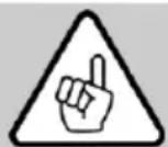
5.2.1 Assignment portal connector
All pins on the portal connector are protected against reverse polarity. At voltages above 30V , continuous operation with reversed polarity must be avoided as this can lead to failure of the PV interface.
| Pin No. | Parameter | Colour of wire Order No. 208311 |
| 1 | UPV | Brown |
| 2 | Us | White |
| 3 | U0 | Black |
| 4 | GND | Blue |
5.3 Speed specification
With the setting wheel X (Fig. 2) you can adjust the speed continuously. The concrete speed values of individual stages can be found in the table on page 5 or on the speed sticker on the housing.
Until the motor characteristic is reached, the built-in electronics readjust to the set speed.
5.3.1 Speed setting in PV design
In "portal mode", the position of the setting wheel X (Fig. 2) for the speed setting is ignored. The speed can only be changed by the voltage at the pin "U s". If you wish to set the speed by means of the setting wheel X (Fig. 2), "portal mode" must first be deactivated by switching off the power supply at the pin "UPV" or by removing the PV control cable.
The correlation between speed and control voltage is illustrated in formulae (1) and (2).
$$ \begin{array}{l} U s = \frac {n - 4 0 0 0 \min ^ {- 1}}{2 1 0 0 \frac {\min ^ {- 1}}{V}} (1) \ n = U s * 2 1 0 0 \frac {\min ^ {- 1}}{V} + 4 0 0 0 \min ^ {- 1} (2) \ \end{array} $$
5.4 Overload protection

Danger
If you carry out any work on the working spindle after the overload protection has triggered, the mains plug must first be removed.
To protect the milling motor, the operating parameters current, speed and temperature are dynamically monitored and the power tool is switched off if necessary. Shortly before the overload protection is tripped, the illumination of the setting wheel X (Fig. 2) changes to a permanent red (RD).
To put the milling motor back into operation, you must open and close power switch 5 (Fig. 1). The milling motor goes into operation and the illumination of the setting wheel X (Fig. 2) changes to blue (BU).
5.4.1 Optical display of the remaining runtime
Triggering of the overload protection during operation leads to breakage of the milling tool, damage to the workpiece or even damage to the portal system. You can prevent this by paying attention to the visual output signals at the setting wheel X (Fig. 2).
As long as the milling motor is not overloaded in terms of performance, the setting wheel lights up permanently in blue (BU).
If the milling motor is overloaded, the calculated remaining runtime is displayed flashing in red (RD). On page 6 (Fig. 7) you can see the temporal arrangement of the pulses in overload mode. The correlation between the flashing behaviour and the associated remaining runtime is shown in the bottom table 4 on page 31.
If the remaining runtime is not sufficient for your application, reduce the load or feed rate to be able to switch back to continuous operation.
5.4.2 Display of the remaining runtime in the PV design
If the milling motor is in "portal mode", the remaining runtime can be queried via the PV interface in addition to the visual display.
The bottom table shows the correlation between the remaining runtime and the associated output variables.
Table 4: Correlation between the remaining runtime and the associated output variables
| Operating mode | Remaining runtime /s | Display remaining runtime U0/V | Setting wheel -illumination |
| Continuous operation | unlimited | 0 | Blue (BU), permanent |
| Overload mode(motor is running) | < 160 | 1.5 | 1 x red pulse (RD) |
| < 80 | 2.5 | ||
| < 40 | 3 | 2 x red pulse (RD) | |
| < 20 | 4 | ||
| < 10 | 4.5 | 3 x red pulse (RD) | |
| < 5 | 5 | Red (RD), permanent | |
| Switch-off | 0 | 5 |
6 Service and maintenance

Danger
Pull the power plug during all service work.
MAFELL machines are designed to be low in maintenance.
Replace the carbon brushes at the latest after 125 - 150 operating hours. The spare parts can be referenced in chapter 9.
The ball bearings used are greased for life. When the machine has been in operation for a longer period of time, we recommend to hand the machine in at an authorised MAFELL customer service shop for inspection.
Have your power tool serviced by a qualified repair person using only identical replacement parts. This will ensure that the safety of the power tool is maintained.
6.1 Storage
If the milling motor is out of service for a lengthy period of time, it should be thoroughly cleaned. Spray bright metal parts with a rust inhibitor. Close the portal connector with the supplied covering cap Z (Fig. 4).
7 Troubleshooting

Danger
Determining the causes for existing defects and eliminating these always requires increased attention and caution. Pull the mains plug beforehand!
Some of the most frequent defects and their causes are listed in the following chart. In case of other defects, please contact your dealer or the MAFELL customer service directly.
| Defect | Cause | Elimination |
| The milling motor cannot be switched on The setting wheel does not light up | There is no mains voltage | Check the power supply |
| The mains fuse is defective | Replace the mains fuse | |
| The milling motor cannot be switched on. The setting wheel lights up in blue (BU) | The carbon brushes are worn | Take the milling motor to the MAFELL customer service |
| The milling motor stops during operation. The setting wheel does not light up | Mains failure | Check the mains back-up fuses |
| The milling motor stops during operation. The setting wheel lights up in red (RD) | The overload protection was triggered | Switch off the power switch. Clear the working spindle before initial operation Switch on the power switch and continue operation with reduced load/feed rate |
| The speed cannot be adjusted at the setting wheel | The milling motor is in portal mode | Switch off the power supply of the PV interface Remove the external connection of the PV interface |
| The speed cannot be controlled via the PV interface | The power supply of the PV interface is missing / is inadequate | Switch on the power supply of the PV interface in accordance with the specification |
| The contacting to the portal connector is insufficient | Check the contacting | |
| The PV control cable is defective | Replace the PV control cable | |
| The assignment of the PV interface is incorrectly connected with the portal system | Connect the PV control cable according to chapter “Assignment portal connector” |
8 Optional accessories
- Collet OZ8 2 mm Order No. 093819
- Collet OZ8ø3mm Order No.093812
- Collet OZ8 0.4 mm Order No. 093813
- Collet OZ8 05 mm Order No. 093820
- Collet OZ8 6 mm Order No. 093814
- Collet OZ8 0 8 mm Order No. 093815
- Collet OZ8 0 10 mm Order No. 093822
- Collet OZ8 01/8" (3.175 mm) Order No. 093810
- Collet OZ8 0 1/4" (6.35 mm) Order No. 093811
- Collet OZ8 0.3 mm + union nut Order No. 093816
- Collet OZ8 01/8" (3.175 mm) + union nut Order No. 093817
- Collet ER 16ø3mm Order No.093753
- Collet ER 16ø4mm Order No.093754
- Collet ER 16ø6mm Order No.093755
- Collet ER 16ø8mm Order No.093756
- Collet ER 16 ø 3.175 mm (1/8") Order No. 093757
- Collet ER 16ø10 mm Order No.093759
- Collet ER 16ø6.35 mm (1/4") Order No.093760
- Union nut OZ8 Order No. 093818
- Union nut ER 16 M Order No.093758
-Adapter sleeve 3mm Order No.207944
-Adapter sleeve 1 / 8" (3.175 mm) Order No.207945 - Adapter sleeve 1 / 4" (6,35 mm) Order No. 207947
-Adapter sleeve 4mm Order No.207949
-Adapter sleeve 6mm Order No.207946 - Collet adapter OZ8 incl. union nut OZ8 Order No. 208962
- Collect adapter ER 16 incl. union nut ER 16 Order No. 208109
- PV control cable M8 / 4-pol, 5 m Order No. 208311
9 Exploded drawing and spare parts list
The corresponding information in respect of spare parts can be found on our homepage: www.mafell.com
Sommaire
9M0001, 9M0020, 9M0021, 9M0023
9M0201, 9M0223
9M0401, 9M0423
9M0101
9M0301, 9M0323
9M0001, 9M0020, 9M0021, 9M0023
9M0201, 9M0223
9M0401, 9M0423
9M0101
9M0301, 9M0323
9M0001, 9M0020, 9M0021, 9M0023
9M0201, 9M0223
9M0401, 9M0423
9M0101
9M0301, 9M0323
9M0001, 9M0020, 9M0021, 9M0023
9M0201, 9M0223
9M0401, 9M0423
9M0101
9M0301, 9M0323
9M0001, 9M0020, 9M0021, 9M0023
9M0201, 9M0223
9M0401, 9M0423
9M0101
9M0301, 9M0323
9M0001, 9M0020, 9M0021, 9M0023
9M0201, 9M0223
9M0401, 9M0423
9M0101
9M0301, 9M0323
4 Forbereda/stalla in
4.1 Natsaslutning
Atdragningsmoment for kopplingsmutter/spannhylsa = 10 -11 Nm
Atdragningsmoment for spannhals 43mm = 7Nm
9M0001, 9M0020, 9M0021, 9M0023
9M0201, 9M0223
9M0401, 9M0423
9M0101
9M0301, 9M0323
2.1 Producentinformationer
MAFELL AG, Beffendorfer Straße 4, D-78727 Oberndorf / Neckar, Telefon +49 (0)7423/812-0, fax +49 (0)7423/812-218, e-mail mafell@mafell.de
9M0001, 9M0020, 9M0021, 9M0023
9M0201, 9M0223
9M0401, 9M0423
9M0101
9M0301, 9M0323
2.1 CBeHeHnO npOn3BoNDTeNe
MAFELL AG, Beffendorfer Straße 4, D-78727 Oberndorf / Neckar, Teilepoh +49 (0)7423/812-0, φακε +49 (0)7423/812-218, ηλ. noúτa mafell@mafell.de
2.2 MapKnpOBKa MaunHbI
Bce daHHbIe, Heo6xOaMbIe IINr IHeHTnФkaCmMaunHbI, yKa3aHbI Ha 3aBOcKo Ta6JNueKe.

Knacc 3auntbI II

Cnmbon CE nnoTBepeHne HcOoTBeCTBnO OCHOBbIM Tpe6oBaHnM 6e30nacHocn n 3dpabooxpaHeHn corlacho npJIOXeHnIO I K DnpeKtNBe o Maunhax

Tonbko dnn ctpaH EC
He BbIKnDbIbAaTe Φpe3epHbIe DnBraTeN B 6bITOBoM Mycop!
Cornacno Ebponecko dnpekTbe 2002/96/EC o6 yctapeBuxx 3neKtpuecknx n 3neKTPOHbIX npnbopax u aHaIOnuHbIM 3aKoHaM OTdeJbHbIX CTpaH, IcNoJIb3OBAHHbIe fpe3epHbIe DBnraTeJI NdoJIKHbI CObnapbCra OTdeJIbHO IN nepeDaBaTbcr dna daNbHeIwero nCpOJIb3OBAHn8 Be3 yUepe6a dnn OkpykaIoSei cpebl.

IpoHTaTe HnCTpyKcHIO NO 3KcNpyatauIN dIyMeHbSeHnO nacHOCTn NOnyHeHn TpaBM.
2.3 TexHnueckne xapaKTepeNcTnKn
| FM 800 | FM 1000 | FM 1000 PV | FM 1000 PV-ER | FM 1000 WS | FM 1000 PV-WS | FM 1000 (120 B) | |
| Равоче наразожения / B | 230 | 230 | 230 | 230 | 230 | 230 | 120 |
| Частota в сети / Гц | 50 | 50 | 50 | 50 | 50 | 50 | 60 |
| ПOTравлиая мошость /Вт | 800 | 1000 | 1000 | 1000 | 1000 | 1000 | 1000 |
| Номналыя сима тoka / A | 4,0 | 4,6 | 4,6 | 4,6 | 4,6 | 4,6 | 8,3 |
| Нразожения пitaшия / B* | - | - | 8 - 56 | 8 - 56 | - | 8 - 56 | - |
| Нразожения в цelenу уразWIENЯ ддпразварITIELноюпостroduki чASTOTBI вразшия / B* | - | - | 0 - 10 | 0 - 10 | - | 0 - 10 | - |
| Быcod octabшEROбя врemeи / B* | - | - | 0 - 5 | 0 - 5 | - | 0 - 5 | - |
| ПOTrabлесенie зелковские / MA | - | - | 3 - 5 | 3 - 5 | - | 3 - 5 | - |
| Частota вразшия нахолocTom xOdu / MmH-1 | 7000-25000 | 4000-25000 | 4000-25000 | 4000-25000 | 4000-25000 | 4000-25000 | 10000 -25000 |
| Зжим Истчима сцанговIM патоном / MM | 6 | 8 | 8 | 8 | 8 | 8 | 6,35(1/4") |
| Хвостовik Истчима / MM | 3 - 8 | 3 - 8 | 3 - 8 | 3 - 8 | 3 - 8 | 3 - 8 | 3 - 8 |
| Фраза / Мк. / MM | 36 | 36 | 36 | 36 | 36 | 36 | 36 |
| Шпфовальский Крг / Мк. / MM | 40 | 40 | 40 | 40 | 40 | 40 | 40 |
| Вес бezс сөтевого кабеля / кг | 1,6 | 1,6 | 1,6 | 1,6 | 2,8 | 2,8 | 1,6 |
| Длиа се dingintelhoилини / M | 1 | 4 | 0,75 + 4 | 0,75 + 4 | 4 | 0,75 + 4 | 4 |
| Размеры (ш x Д x В) / MM | 73 x254 x79 | 73 x254 x79 | 73 x254 x79 | 73 x254 x79 | 92 x280 x85 | 92 x280 x85 | 73 x 254 x 79 |
* DaaHbIe IJIa INTepeEca nOPTaIa (INTepeEca PV)
2.4 Bb16poc
Yka3aHHbIe 3NaueHnI npedctabnIOT cO6o EmCCNOHbI yPOBeH. XOTy cyuectByeT CBra3b MeJdy yPOBHM BbIeJIeHnI INPOHKnHOBeHn, PO 3OMy HeIb3r Cydntb O Heo6XODMOCt DOnONHITbHbIX Mep IpeIOCTOPOXHocTN. PhAKTOPbI, BInyaUOHe Ha cyuectByOUsn Ha pa6Oyem MeCTe yPOBeH bUyma, BKIOUaHT IpoDIOJIKHTbBO3deIcTBnI, XapaKTepNCtIKN NOMESeHn, dpyrNe IcTOHnKn UWMa n T.I., HAnp., KOnNUeCTBO CTAHKOB I BbINOpHEHn PdOM dpyrNX pa6OuHX onepaun. Kpome TOrO, DoNyCTmbl yPOBeH Wyma MoKet pa3NIuATbcR B 3aBnCIMOCtN OT cTpaHbI. Tem He MeHee, 3Ta IHΦOpMaun No3BOJNT POnb30BaTeJILO LyUWe OuceHHTb ONACHOCTb n PnCKn.
2.4.1 DaaHHbIe no n3JnyeHnIO wyma
YpOBHn yUma, n3MepeHHbIe corJaacHO DIN EN ISO 3744, coCTaBJIaIOT:
ypOBeHb 3ByKOBOrO daBJIeHnRA LpA 71 D5 (A)
πorpeuhoctb KpA3D5(A)
ypoBHe 3ByKOBoMooHocTn LwA82D5(A)
πoRpeuHocTb KwA3D5(A)
I3mepenHe yMa npOboDInocb 6e3 INHCTpyMeHTa Ha XOJIOCTOM XOy.
2.5 KomnneKT noctabkn
| FM 800 | FM 1000 | FM 1000 PV | FM 1000 PV-ER | FM 1000 WS | FM 1000 PV-WS | |
| Иnstрукция по эксплуатаци | x | x | x | x | x | x |
| Односторонni 栙echь Клоч SW 17 | x | x | x | - | - | - |
| Односторонni 栙echь Клоч SW 25 | - | - | - | x | - | - |
| Цанговий патон OZ8 ø / MM | 6 | 8 | 8 | - | - | - |
| Цанговий патон ER 16 | - | - | - | 8 | - | - |
| Кабел / m | 1 | 4 | 0,75 + 4 | 0,75 + 4 | 4 | 0,75 + 4 |
| Крышka Z | - | - | x | x | - | x |
2.6 NcnoJb3ObaHne no Ha3HaueHnIO
- Φpe3epHbI nDbIaTeIb npedHa3HaueH IJIe CTAUHOHApHOYCTAHOBKn B BeDyuxxCCTeMaX nopTaNa C 3axHMHO WeKo 43 MM.
- Φpe3epHbI DnBraTeIb C 6bICTpbIM 3aXIMOM MOXHO 3aKpeNtB HENOCpeICTBEHNO Ha CnCTeMe NopTaJa C nOMOujo WeCTn BnHTOB (pe3b6a M6) B COOTBeTCTBnC O CneUΦnKaUmaMn CnCTeMbI NOpTaJa (pnc.5).
- Φpe3epHbI DnBaTeIb He npEdHa3HaueH dIe HnpepbIBHO npOMbIwIeHHO 3KcNpyaTauIN.
- Φpe3epHbI DvBraTeJIb paccMaTpmbaETcKaK HEnoJHa MaunHa. Φpe3epHbI DvBraTeJIb MoXeT 6bITb BBeDeH B 3KcPJIyatauIO TOJbKO B TOM Clyuae, ecN ONpeJeHeO, YTO CNCTema NOpTaIa, B KOTopyUdoJIKHe 6bITb yCTaHOBJIeH φpe3epHbI DvBraTeJIb, COOTBEcTBByET NOIOKeHNM DeIcTBYIOePOykoBOdCTBa IIO TexHnueCKOMy OScJyXnBAHIO. TaKke Obpatnte BHIMAHne Ha COOTBEcTBYIOme YCIOBnaIraPANTM φpe3epHoro DvBraTeJIa IIObOro DOONHNTbHOrO ObOpyDoBaHInr.
2.7 OctaToHbIe pNcKn

Onacho
B cnlyae nncnoIb3ObaHn no Ha3NaueHnIO n HeCMOTpHa co6JIHOJeHne npaBnI TexNk 6e3OpacHOCTn BCE Xe OCTaIOTCra OCTaTOUHbIe PNCK, Bbl3bIBaEmble Ha3NaueHnEM, KOtOpBle MOrYT npNBecTNI K NocJIeCTBnM dJa 3DopOBbJ.
-ПоломkaВрацаюцeroинстурента.
-ПоломkaиИЗВлесенеИнструментовИпчсей Инструментов.
- Kacahne TokonpoBODaIcx DeTaNep NpN OTKpbITOM Kopnyce N He BbITaHyToB BNJIke NITaHna.
- YxuDSeHHe cnyxa npn dInTeBHo pa6oTe 6e3 cpeCTb 3aunTbI opraHOB cnyxa.
- Bыдение п徴дстався угозу здорови взрьюнанов nbi (BCEX BIDOB) рп дintelhoн He nppepbHON ekcnnyatau6e3 OTCoca. Co6niOdaTe nacnpT 6e3onacHocTn MaTePnaJa, noDneJxauero o6pa6oTke.
3 Yka3aHnno TeXnke 6e3OpacHOcTn

Onacho
Bcerda co6nOdaIte npBedeHbIe daIee yka3aHna IIO 6e3oNaChocTn n npabNnA texHnKn 6e3oNaChocTn, DeIcTByUoUne B cTpaHe, rIe npImMeHReTc nnla!
06uhe yka3aHn:
- 3anpeuaeTc8 o6paatb8c8 c 3to8 Maunnoi TETM n noDPOCTKAM. NcknueHne coCTaBnIOT noDPOCTKN, paobTaUo7e NOd HabnOHeHem CneuaNtca C ceMbO obyehna.
- Hnkorda He pa6oTaIe 6e3 npedncaHHbIX dIra COOTBeTCTByOuIe Ionepaun 3aunTHbIX yCTpoiCTB cnCTembl nopTala, B KOTopoI nCNoIb3yETcF ppe3epHbI DnuratJIb. He MeHnIte B CnCTeme npTana I ppe3epHom DBnuratIe Hnueero, YTO CBra3aHO C TexHniko 6e3onacHOCTn.
-Повржденье Кабели Ил ВИКи СпедуET HeMeДпЕнHO 3aMeHNTb. 3aMeHa DoJIXHa ПОИЗВОДИТсЯТолько спесиалICTamM Mafell Ил abTOpI3OBaHHbIM cepBnCHbIM ueHTpOM Mafell BO nI36ExKaHne pIcKOB yrpo3bl Дя 6e3OpaNacHocTn. - I36eraIte pe3Knx nepern6ob Ka6eJ. Oco6eHNO npi TpaHcnpTupOBke n xpaHeHHn 0pe3epHoro dBirataJI He HaMaTbIbAitc Ke6JIb BOKpyr 0pe3epHoro DBrataJIe.
- IcnoJIb3OBAHnE C BOIo NII TOKOpBOJzIMN XJUKOCTaMn 3aPpeIeHO.
- IcnoIb3ObaHne B kaueCTBe puHoro fpe3epHoro DnBraTeJIA NCKNoUeHO.
- He podBepraTe fpe3epHbI dBuraTeIb BO3eJCTBIO DOxJa NII BlaRn. IonaDaHne BObl BO fpe3epHbI dBuraTeIb NOBbIaaeT onaCHOCTb NOPaXeHnE 3JIeKTPuYeCKm TOKOM.
He pa3pewaetca nCnoJb3oBaTb:
- NobpeKdEHHbIe IeOpMnPoBaHHbIe INHCTpyMeHTbl.
TynbIe INHCTpyMeHTbl N3-3a CnNtKOM 6oNbWOn Harpy3Kn DBrVaTeJIa. - INCTpymEnTbI, KOTOpBIE He NOxOJaT dJa YacToTbI BpaUeHnA fpe3epHOro DbrVaTeJHa XONOCTOM XOyJ.
Yka3aHnno npimHeHnO cpeCTB JIyHoi 3aunTbI:
-BoBpempa60TbBCerdaNCnoJb3ObaTb3aunTy opraHOB cIyxa.
-BoBpempa60TbBCeIgdaNCIOJIb3OBA Tb npOTIBONblneBOI pecnnpaTop.
- Ppi pa6oTe Hocnte 3aunTHbIe OCHN.
Yka3aHn no 3Kcnnyatau:
- He npikacaiTecb pykam K onachomy yuactky uHCTpymeHTa.
- PpOBepaIe 3arOTobKy Ha HauHnUne HOpOdNbIX TeI.
- KoHTpOJIpyTe YacToTb VpaUeHn. Pn B03HnKHOBeHn HeKOHTpOJIpyEmo rYBeJIuYeHn YactOTbI BpaUeHn, cKaUc KaCToTbI BpaUeHn, Heo6XoDmO HemeJInHNo OTKlIOuHTb 3JIeKTPOINHCTpyMeHT OT NCTOHHa NITAHn.
Yka3aHnno TeXnueckomy o6cnyxBaHnIO n TeKyuemy pemOnTy:
- PerylnpHaN qIcTka fpe3epHoro DnBraTeJRAJIeTc Baxhblm paKTopoM HaJeXHOCTN
- Pa3pe7aetcI cnoJIb3OBAHHe TOnbKO opuHaJIbHbIX 3aNaChbIX qAcTei I npHaJNeXHOCTeI φnpMbIMAFELL. B npOTnBHom cIyue pTeH3nn, OTHOcIaMeCk K rapaHTmN O TBETCTBeHHOCt N3rTOBNTeJI, He npINHMaiOTcI.
4 Ochauene / NaCTpOka
4.1 PoiKJIIOUeHne K cETn
Ipeed BBODOM B 3KcNpyaTaunO CneDnTe 3a TeM, YTObI HAnpJxHHe B CeTn COOTBeTCTBOBaIO pa6oYeMy HAnpJxHHeIO, yKa3aHHOMy Ha 3aOBdCKoTabnUKe fpe3epHOrO DBrGaTeJI.
4.2 Bb6op mHcTpymeHa
IcnoJb3yJte TOnbKO yka3aHHbIe B rnaBe «CneuaJIbHbIe npHaJdNExHoCTn» ZaHROBbIe naTPOhbl/peXoHbIe Btyn. BbIbOp IHcTpymEHTa OcyuEcTBnIeTcB 3aBNCmOCTn OT MaTePnAnOB, NOJExKaUnx Obpa6OTke, C yueToM MoUHOCTn NODaIOUx npIBoDob. Pn MaKcMaJIbHOM DnAmEtpe INHcTpymEHTa n rIy6InHe Obpa6OTkn yuHTbIaIe MOUHOCTb φpe3epHOrO DBnraTeJIa.
4.3 OndeBaIte

Onacho
При поведени лобьх paBOT NO ТхнчecOMу obcnyЖиBaHIO BbIHMaTb BnKy coeINHTelbHOrO shhya.
IcnoJIb3yIte 3aUHTbIe nepuATkn npu CMeHe HhCTpyMeHtA. IcnoJIb3yeMbI INHCTpyMeHr MOxET CINbHO HArpeBaTbC8 BO BpEraДПITeJIbHOrO IcNoJIb3OBaHnR, n/Inn peKxUne KpOMKn IHCTpyMeHtA OCTpbIe.
4.3.1 3axim nHcTpymeHTa c nOmoIbU caHroBOro naTpoHa
1 (pnc. 1) 6pe3epHO-7nnpoBaIbHOrO DnIraTeIg OChaIeH npeu3HOHHbIM cHaHROBbIM naTPOHOM 2 (pnc. 1) dna 3axmMa IHcTpymEtOB. BLOKIpOBKa 7nnHdJIeO CyUeCTBJIeTc C NMOU KHOKN 6loKIpOBKn 4 n obneruae 3aTgNBaHne i ocna6IeHne HAKINHO raIKN 3 (pnc. 1).
CmeHa INcTpymeHtA ocUeCTBnIeTcB CJIeNyIOuem NopJdKe:
- Yto6bI ChraTb INHCTpyMeHT, 1 (pnc. 1) 6JOKnpyH T HxKaTneM KHOKn 6JOKnpoBkn 4 (pnc. 1).
- HakuHyu raiky 3 ocna6IOT oDIOcTOPOHHIM raeHbIM KIOUOM SW 17 nn 3aKmHbIM KIOUOM ER 16 M.
- INHCTpymEnT BbITaRnBaIOT BnepeId.
- HoBbI INHCTpymeHT BCTaBnIOT Do yIopa B 3aXIM INHCTpymeHTa.
-Поберп Te nocaДу ИНСтчмЕТа.
-ПризakpenlenHHNcTpymenta6nOKpyetcaWnHdJIb1(pnc.1). - Hakuhyo raiky 3 3aTgBaIOT oHocToPOHHm raeHbIM KIOUOM SW 17 nn 3axmmhBIM KIOUOM ER 16 M.
4.3.2БысторкpenJIeHneИнсTpymeHTa
BknouaTe qpe3epHbI DnRaTeIb TOnbKO TOrda, KOrda pbUar 6 (pnc. 3) He HaxoNTcR B NIOJKeHN CMeHb I NHCTpyMeHTa.
NcnoIb3yIte pbIar 6 (pnc. 3) TOnbKO npn OTKJIIOyeHHOM fpe3epHom DBNraTeNe.
Пиндь 7 (pnc.3) bICTporo KpePJIeHnI INCTpyMeHTa OCHaUeH npeu3IOHHbIM 3aXIMOM IЯ XBOCTOBNka INCTpyMeHTa 08 MM.
CmeHa HnctpymEnTa ocuueCTBnaTcB cneDuOeM nopAdke:
- Yto6bI cHraTb IHcTpymeHT, nepemecntte pbiur 6 (pnc.3) Bnpeed do ynpa.
- INHctpymeHT BbITrIbAIOT Bnpepe.
-HobbHnCTpyMeHT BCTaBnHO T Do ynpa B 3axm HnCTpyMeHTa. - PpOBepbTe nocaKy INHCTpyMeHTa.
- 4to6bI 3akpenntb HnctpymEnT, nepemecntte pbuarg Ha3aB B nCXoJHoe noIOxKeHne.
4.4 ZaHroBbI naTpoH

Onacho
HaiknHyraky 3 (pnc.1) Ha uHHne 1 (pnc.1) OTBnHnBaTe octopoxHo, TTO6bI 3aunTb pe3bOy, HNKoRa He 3aTnBaTe ee, ecN He yCTaHOJIeH INCTpyMeNT. LcAHOBIn NaTPOH 2 (pnc.1) MoKET 6bITb CnNtKOM CnNbHO 3aXaT, n, TAKIM O6pa30M, NOBpeJKeH.
4.4.1 HOpMaun o6 nCnoB3ObaHnn ZaHroBbIX naTPOHOB:
C zauHroBbIM natoHOM OZ8 (DIN 6388 / ISO 10897) u ER16 (DIN 6499 / DIN ISO 15488) u cnoIb3ynte
- Bcerda cnaaana BCTabIyTe IaHroBbI nATPOH B HAKnHyIO raIKy, a 3aTEM BCTabNJIte pe3y
- B cnuyae 3aknnnHbAHnOcna6bTe zanroBbI naTPOH cnerKa yapnb erO c3aN KBaPaTHbIM bpycom n pe3HHOBbIM MOJOTKOM (He MeTaJIInueCKM INHCTpyMeHTOM!)
- Cma3bIbaiTe zauHroBbIe natoHbI nepei nepBOI kcnnyatauei I nocne dInTeBHO rnoB3OBaHn He6oJIbIM KOJIyecTBOM Macna, HNaye OHN MOrTy 3acTpyTb
- 3начтелбно Лушев точно врашеня takke мохно дocиь, Incnoьзу Тьердую сma3ky (Hapimep, Molykote P-40) ил сlerka сma3bIBaя санroBsп ratpoHbI
4.4.2 PekomeHdyembIM MOMENT 3aTjKKn (yUHTbIbaIe BCIO CnCTEmy)
Momet 3aTJKKn HAKINHOI raiKu / ZaHROBOro naTpoHa = 10-11 Hm
Moment 3aTJKK 3aKIMHOn WeiKn 43 MM = 7 Hm
EbpokpenneHHeNoJHKHO6bITbMeHbse pa3Mepa h (pnc.8).Pa3Mep h coCTabJIaER 20 MM.
3aXMMTe 0pe3epHbI DnBraTeIb KaK MOxHO CnIbHee NO BCeMy DnaMeTpY eBpokpenHeHNA «V1» (pnc. 8).
3aTAYbCTXKHOB BnHT W cMaKc. yCJInem 7 Hm. (Pnc.9)
9M0001, 9M0020, 9M0021, 9M0023
9M0201, 9M0223
9M0401, 9M0423
9M0101
9M0301, 9M0323
2.1 Dane dot.producenta
MAFELL AG, Beffendorfer Straße 4, D-78727 Oberndorf / Neckar, Telefon +49 (0)7423/812-0, Faks +49 (0)7423/812-218, e-mail mafell@mafell.de
9M0001, 9M0020, 9M0021, 9M0023
9M0201, 9M0223
9M0401, 9M0423
9M0101
9M0301, 9M0323
2.1 Udaje k vyrobci
MAFELL AG, Beffendorfer Straße 4, D-78727 Oberndorf / Neckar, Telefon +49 (0)7423/812-0, Fax +49 (0)7423/812-218, E-Mail mafell@mafell.de
2.2 Charakteristika stroje
9M0001, 9M0020, 9M0021, 9M0023
9M0201, 9M0223
9M0401, 9M0423
9M0101
9M0301, 9M0323

- AVERTISSEMENT
- GB - EC - Declaration of Incorporation
- Signs and symbols
- Product information
- Manufacturer's data
- Machine identification
- Technical data
- Emissions
- Noise emission specifications
- Scope of supply
- Use according to intended purpose
- Residual risks
- Danger
- Safety instructions
- General instructions:
- Do not use:
- Instructions on the use of personal protective equipment:
- Instructions on operation:
- Instructions on service and maintenance:
- Setting / Adjustment
- Mains connection
- Selection of tools
- Tool change
- Tool clamping by means of collet
- Quick tool clamping
- Collets
- Information on the use of collets:
- Recommended tightening torques (observe overall system)
- Maximum speed when using a collet adapter
- Operation
- Initial operation
- Switching on
- Switching off
- PV design
- Assignment portal connector
- Speed specification
- Speed setting in PV design
- Overload protection
- Optical display of the remaining runtime
- Display of the remaining runtime in the PV design
- Service and maintenance
- Storage
- Troubleshooting
- Optional accessories
- Exploded drawing and spare parts list
- Sommaire
- Forbereda/stalla in
- Natsaslutning
- Producentinformationer
- CBeHeHnO npOn3BoNDTeNe
- MapKnpOBKa MaunHbI
- Bb16poc
- DaaHHbIe no n3JnyeHnIO wyma
- KomnneKT noctabkn
- NcnoJb3ObaHne no Ha3HaueHnIO
- OctaToHbIe pNcKn
- Onacho
- Yka3aHnno TeXnke 6e3OpacHOcTn
- 06uhe yka3aHn:
- He pa3pewaetca nCnoJb3oBaTb:
- Yka3aHnno npimHeHnO cpeCTB JIyHoi 3aunTbI:
- Yka3aHn no 3Kcnnyatau:
- Yka3aHnno TeXnueckomy o6cnyxBaHnIO n TeKyuemy pemOnTy:
- Ochauene / NaCTpOka
- PoiKJIIOUeHne K cETn
- Bb6op mHcTpymeHa
- OndeBaIte
- 3axim nHcTpymeHTa c nOmoIbU caHroBOro naTpoHa
- 4.3.2БысторкpenJIeHneИнсTpymeHTa
- ZaHroBbI naTpoH
- HOpMaun o6 nCnoB3ObaHnn ZaHroBbIX naTPOHOB:
- PekomeHdyembIM MOMENT 3aTjKKn (yUHTbIbaIe BCIO CnCTEmy)
- Dane dot.producenta
- Udaje k vyrobci
- Charakteristika stroje
Brand : Mafell
Model : FM 1000
Category : Milling machine