MM 52 - Multimeter BENNING - Free user manual and instructions
Find the device manual for free MM 52 BENNING in PDF.

| Product Type | Digital Multimeter |
| Brand | BENNING |
| Model | MM 52 (equivalent to MM 5-2) |
| Measurement Category | CAT III 600 V / CAT IV 300 V |
| Display | LCD 4 digits, 6000 counts, 16 mm height |
| Dimensions (without guard) | 138 x 68 x 30 mm |
| Weight (without guard) | 180 g |
| Dimensions (with guard) | 150 x 77 x 44 mm |
| Weight (with guard) | 310 g |
| Power Supply | 2 x 1.5 V batteries type R3 (LR03) |
| Battery Life | Approx. 300 hours (alkaline) |
| Measurement Functions | AC/DC voltage, AC/DC current, resistance, capacitance, frequency, temperature, diode test, continuity |
| Accuracy | TRUE RMS, base 0.5% + 3 digits (DC V) |
| Input Protection | Fuse 15 A / 600 V, 50 kA (for current) |
| Safety | Double insulation (class II), rubber boot with magnet |
| Non-contact Voltage Indicator | Yes, via VoltSensor key |
| Special Functions | Smart HOLD, PEAK, Δ/PEAK, backlight, auto power off |
| Included Accessories | Red/black test leads, temperature probe (type K), rubber boot, pouch, batteries, fuse |
| Temperature Range | 0 to 50 °C (operation), -20 to 60 °C (storage) |
Frequently Asked Questions - MM 52 BENNING
User questions about MM 52 BENNING
0 question about this device. Answer the ones you know or ask your own.
Ask a new question about this device
Download the instructions for your Multimeter in PDF format for free! Find your manual MM 52 - BENNING and take your electronic device back in hand. On this page are published all the documents necessary for the use of your device. MM 52 by BENNING.
USER MANUAL MM 52 BENNING
Multilingual manuals on included CD and at
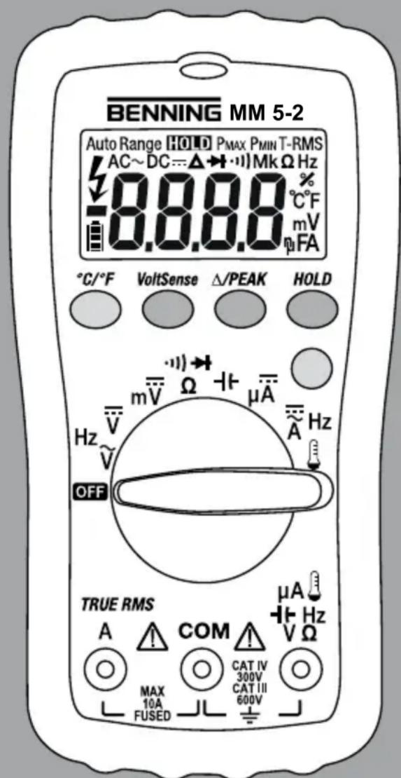

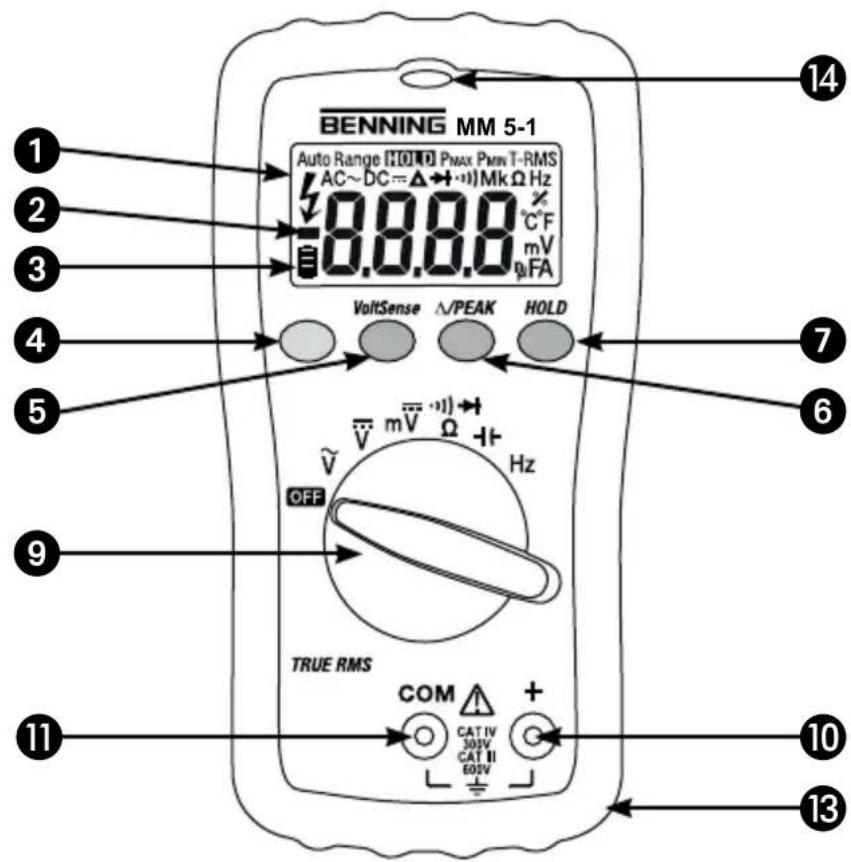
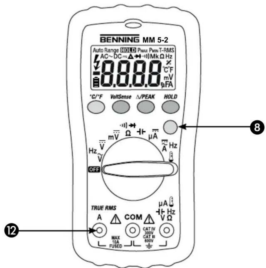
Bild 1: Gerätefrontseite
Fig. 1: Front tester panel
Fig. 1: Panneau avant de l'appareil
Fig. 1: Parte frontal del equipo
Obr.1: Predni strana pristroje
oxma1:Mnpoovn oyn
III. 1: Lato anterioi apparecchio
Fig. 2: Direct voltage measurement
Fig. 2: Mesure de tension continue
Fig. 2: Medicion de tension continua
Obr.2:Mereni stejnosmemeho napeti
Oxyn2: metpnD-
Fig. 3: Alternating voltage measurement
Fig. 3: Mesure de tension alternative
Fig. 4: DC current measurement
Fig. 5: AC current measurement
Fig. 6: Resistance measurement
Fig. 6: Mesure de resistance
Fig. 8: Continuity Testing with buzzer
Fig. 9: Capacity Testing
Fig. 10: Frequency measurement
Fig. 11: Temperature measurement
pnc.12: INHdkatop HaprKeHHA
Resim 12: Gerilim indicatoru
Fig. 13: Battery replacement
Fig. 13: Remplacement de la pile
Fig. 13: Cambio de pila
Obr.13: Vymena baterii
Oyjua 13: Avikataaon mataipiv
Fig. 14: Fuse replacement
Fig. 15: Winding up the safety measuring leads
7.11 PEAK HOLD fur AC V/AC A
Digital Multimeter for
- DC voltage measurement
- AC voltage measurement
- DC current measurement (BENNING MM 5-2)
- AC current measurement (BENNING MM 5-2)
- Resistance measurement
- Diode testing
- Continuity testing
- Capacity measurement
- Frequency measurement
- Temperature measurement (BENNING MM 5-2)
Contents:
- Operating instructions
- Safety notes
- Scope of delivery
- Description of unit
- General data
- Ambient conditions
- Electrical data
- Measuring with the BENNING MM 5-1/ MM 5-2
-
Maintenance
-
How to use the protective rubber holster
- Technical data of the measuring accessories
12.Environmentalnote
1. Operating Instructions
This operating manual is intended for:
- electricians and
- qualified electrotechnical persons
The BENNING MM 5-1/ MM 5-2 is designed for measurements in dry surroundings. It must not be used in electrical circuits with rated voltages higher than 600VDC AC (for more details, see section 6 "Ambient conditions").
The following symbols are used in the operating manual and on the BENNING MM 5-1/ MM 5-2 itself:

Attention! Magnets might affect the correct functioning of cardiac pacemakers and implanted defibrillators. As a user of such medical devices, keep a sufficient distance to the magnet.

Warning of electrical danger!
Indicates instructions which must be followed to avoid danger to persons.

Important, comply with the documentation!
The symbol indicates that the information provided in the operating instructions must be followed with in order to avoid risks.

This symbol on the BENNING MM 5-1/ MM 5-2 indicates that the unit is protection insulated (safety class II).

This symbol on the BENNING MM 5-2 indicates the fuses which it contains.

This symbol on the BENNING MM 5-1/ MM 5-2 means that the BENNING MM 5-1/ MM 5-2 complies with the EU directives.

This symbol appears on the display for a discharged battery.

This symbol indicates the "continuity-testing" application. The buzzer provides an audible signal.

This symbol indicates the "diode-testing" application.

This symbol marks the range "capacity testing".

(DC) voltage or current.

(AC) voltage or current.

Earth (voltage to earth).
2. Safety notes
The instrument is built and tested in accordance with
DIN VDE 0411 part 1/EN 61010-1
DIN VDE 0411 part 2-033/EN 61010-2-033
DIN VDE 0411 part 031/EN 61010-031
and has left the factory in perfectly safe technical condition.
To maintain this condition and to ensure safe operation of the multimeter, the user must observe the notes and warnings given in these instructions at all times.
Improper handling and non-observance of the warnings might involve severe injuries or danger to life.

WARNING! Be extremely careful when working with bare conductors or main line carrier! Contact with live conductors will cause an electric shock!

Attention! Magnets might affect the correct functioning of cardiac pacemakers and implanted defibrillators. As a user of such medical devices, keep a sufficient distance to the magnet.

The BENNING MM 5-1/ MM 5-2 may be used only in electrical circuits of over voltage category III with a maximum voltage of 600V or of over voltage category IV with a maximum voltage of 300V between the conductor and ground.
Only use suitable measuring leads for this. With measurements within measurement category III or measurement category IV, the projecting conductive part of a contact tip of the measuring leads must not be longer than 4mm
Prior to carrying out measurements within measurement category III and measurement category IV, the push-on caps provided with the set and marked with CAT III and CAT IV must be pushed onto the contact tips. The purpose of this measure is user protection.
Remember that work on electrical components of all kinds is dangerous. Even low-voltages of 30 V AC and 60 V DC may be dangerous to human life.

Before starting the multimeter, always check it as well as all measuring leads and wires for signs of damage.
Should it appear that safe operation of the multimeter is no longer possible, it should be shut down immediately and secured to prevent that it is switched on accidentally.
It may be assumed that safe operation is no longer possible:
- if the instrument or the measuring leads show visible signs of damage, or
- if the multimeter no longer works, or
- after long periods of storage under unfavourable conditions, or
- after being subject to rough transportation, or
- if the device or the measuring leads are exposed to moisture.

In order to avoid danger,
- do not touch the bare probe tips of the measuring leads measuring leads,
- insert the measurement leads in the appropriately designated measuring sockets on the multimeter

Cleaning:
Regularly wipe the housing by means of a dry cloth and cleaning agent. Do not use any polishing agents or solvents!
3. Scope of delivery
The following items make up the standard BENNING MM 5-1/ MM 5-2 package:
3.1 one BENNING MM 5-1/ MM 5-2,
3.2 one safety measuring lead, red (L = 1.4m)
3.3 one safety measuring lead, black (L = 1.4m)
3.4 one wire temperature sensor, type K (only BENNING MM 5-2)
3.5 one protective rubber holster with magnetic holder,
3.6 one compact protection carrying case,
3.7 two 1.5V micro (AAA) batteries are integrated into the device,
3.8 one fuse for initial assembly is integrated into the device (BENNING MM 5-2),
3.9 one operating manual.
Note on optional accessory:
- Temperature probe (K-type) made of V4A tube
application: insertion probe for soft-plastic materials, liquids, gas and air
measuring range: -196 °C up to 800 °C
dimensions: length = 210 mm, tube length = 120 mm, tube diameter = 3 mm, V4A (P.no. 044121)
Note on replaceable parts:
- The BENNING MM 5-2 contains fuses for overload protection: One fuse rated 15 A rapid-acting (600 V) 50kA , D = 10.3mm , L = 38.1mm (P.no. 10149447).
- The BENNING MM 5-1/ MM 5-2 is supplied by means of two integrated 1.5V micro (AAA) batteries (IEC LR 03).
The above mentioned safety cable (tested spare part) are approved in accordance with CAT III 1000 V/ CAT IV 600 V and for a current up 10A .
4. Description of unit
See fig. 1: Front panel
The display and operating elements shown in fig. 1 are as follows:
Digital display, for the measurement reading and display for overrange indication.
Polarity display,
3 Battery display,
4 Function key (blue),
5 VoltSensor key, for determining AC voltage to earth,
/ PEAK key, relative value function and peak value storage
Smart HOLD key,
Button (yellow), display illumination,
Rotating switch, for selecting measuring function.
Socket (positive) for V, , - 1 - 1 Hz (+) (BENNING MM 5-1) or for V, , - 1 - 1 Hz, A, (BENNING MM 5-2)
COM socket, joint socket for measurement of current, voltage, resistance, frequency, temperature, capacity, continuity and diode testing,
12 Socket (positive), for 10-A range, for currents up to 10 A
13 Protective rubber holster
LED (red) for voltage indicator 1) The automatic polarity display for DC current and voltage refers to this.
5. General data
5.1 General data on multimeter
5.1.1 The digital display ① is designed as a 4 digit liquid-crystal indicator with 16 mm digit height and decimal point. The highest value displayed is 6000.
5.1.2 The polarity indication functions automatically. Only a polarity contrary to the socket definition is indicated, as "-".
5.1.3 The range overload will be displayed with "OL" or "-OL" and sometimes with an acoustic signal.
Attention: no display or warning by complete overload.
5.1.4 The rotary switch is intended for selecting the measuring function. The measuring range is selected automatically.
5.1.5Voltsensorkey ⑤: The voltage indicator function is intended for localizing AC voltages to earth (see 8.9).
5.1.6 Press the / PEAK key (relative value function) to store the currently displayed value and to display the difference (offset) between the stored measured value and the following measured values. Press the / PEAK key for 2 seconds to switch over to the "PEAK" function (peak value storage). The "PEAK" function detects and stores the positive and negative peak/crest value ( >1 ms) in the mV, V AC/ DC and mA, A AC/ DC function. Press the key to call up Pmax, Pmin and the currently measured value (Pmax, Pmin). Press the key for approx. 2 seconds to switch the device back to normal operating mode.
5.1.7 "Smart HOLD" - storage of measurement reading: When the "Smart HOLD" key is pressed, the measurement reading is stored in the memory. The symbol "HOLD" appears in the display 1 at the same time. If the measured value increases by 50 digit above the saved value the change in measured value is shown by a blinking display and by a signal tone. (changes of measured values between AC and DC voltage/ current will not be recognized).
5.1.8 Press the yellow key to activate the display illumination. The device is switched off automatically after 2 seconds or by pressing the key again. Deactivate the automatic switch-off by pressing the key (yellow) and simultaneously switching the BENNING MM 5-2 ON from the switch
position "OFF".
5.1.9 The function key (blue) 4 serves to select the secondary or third function of the rotary switch position.
5.1.10 The nominal measurement rate of the BENNING MM 5-1/ MM 5-2 is 2 measurements per sec. for the digital display.
5.1.11 The BENNING MM 5-1/ MM 5-2 is switched on and off by the rotating switch Switch-off position "OFF".
5.1.12 The BENNING MM 5-1/ MM 5-2 switches off automatically after approx. 20 minutes (APO, Auto-Power-Off). It will switch on again as soon as a key is pressed. Deactivate the automatic switch-off by pressing the function key (blue) and simultaneously switching the BENNING MM 5-1/ MM 5-2 ON from the switch position "OFF".
5.1.13 Check the segments of the digital display by pressing the "Smart HOLD" key and simultaneously switching the BENNING MM 5-1/ MM 5-2 ON from the switch position "OFF".
5.1.14 Temperature coefficient of measurement value: 0.1× (stated measurement accuracy) ^ C < 18~^ C or >28^ relative to the value at the reference temperature of 23^
5.1.15 The BENNING MM 5-1/ MM 5-2 is supplied by means of two 1.5V micro (AAA) batteries (IEC LR 03).
5.1.16 The battery display 3 permanently shows the remaining battery capacity over a maximum 3 segments.
#
As soon as all segments in the battery symbol have gone off and the battery symbol blinks please exchange the battery for a new battery immediately in order to avoid a risk through false measurements for people.
5.1.17 The life span of a battery is approx. 300 hours (alkali battery).
5.1.18 Appliance dimensions:
(L× W× H) = 138× 68× 30mm without protective rubber holster (L× W× H) = 150× 77× 44mm with protective rubber holster Weight:
180 g without protective rubber holster
310 g with protective rubber holster
5.1.19 The safety measuring leads are expressly suitable for the rated voltage and power of the BENNING MM 5-1/ MM 5-2.
5.1.20 The BENNING MM 5-1/ MM 5-2 is protected against mechanical damage by a protective rubber holster. The protective rubber holster allows to set up the BENNING MM 5-1/ MM 5-2 when making measurements or to attach it by means of the integrated magnet.
6. Ambient conditions
- The BENNING MM 5-1/ MM 5-2 is designed only for measuring in dry surroundings,
Maximum barometric height during measurement: 2000m - Overvoltage category / setting category: IEC 60664/ IEC 61010-1 600 V category III; 300 V category IV.
- Degree of contamination: 2.
- Protection class: IP 30 (DIN VDE 0470-1 IEC/ EN 60529).
IP 30 means: Protection against access to dangerous parts and protection against solid impurities of a diameter >2.5mm , (3 - first index). No protection against water, (0 - second index). - Operating temperature and relative humidity: At operating temperatures of 0^ to 30^ : relative humidity under 80% . At operating temperatures of 30^ to 40^ : relative humidity under 75% .
- At operating temperatures of 40^ to 50^ : relative humidity under 45% .
Storage temperature: The BENNING MM 5-1/ MM 5-2 can be stored at temperatures from - 20^ to +60^ (humidity 0 up to 80% ). The batteries must be removed from the unit.
7. Electrical data
Note: The measurement accuracy is stated as the sum of
-
a relative proportion of the measurement value and
-
a number of digits (i.e. numerical steps of the last place).
This measurement accuracy applies for a temperature of 18^ to 28^ and a maximum relative humidity of max. 80% .
The measurement value is obtained as a true RMS value (AC coupling) and displayed as such. Square-wave signals (>100Hz) are not specified. With non-sinusoidal curves, the value displayed is less accurate. This results in an additional error for the following crest factors:
Crest factor of 1.0 to 2.0, additional error +1.0% .
Crest factor of 2.0 to 2.5, additional error +2.5% .
Crest factor of 2.5 to 3.0, additional error +4.0% (applies to up to 4000 digits).
7.1 DC voltage ranges
The input resistance is 10M
Overload protection: 600V_AC / DC
Measuring range OL indication Resolution Measurement accuracy
6.000 V 6.600 V 0.001 V ± (0.5 % of reading + 3 digits)
60.00 V 66.00 V 0.01 V ± (0.5 % of reading + 3 digits)
600.0 V 660.0 V 0.1 V ± (0.5 % of reading + 3 digits)
7.1.1 DC voltage ranges mV DC
The input resistance is 10M
Overload protection: 600V_AC / DC
Measuring range OL indication Resolution Measurement accuracy
600.0 mV 660.0 mV 0.1 mV ± (0.5 % of reading + 5 digits)
7.2 AC voltage ranges
The input resistance is 10M parallel < 100~pF
Overload protection: 600V_AC / DC
| Measuring range | OL indication | Resolution | Measurement accuracy in frequency range 45 Hz - 500 Hz (sine) |
| 600.0 mV | 660.0 mV | 0.1 mV | ± (2.5 % of reading + 5 digits)* |
| 6.000 V | 6.600 V | 0.001 V | ± (1.0 % of reading + 3 digits) |
| 60.00 V | 66.00 V | 0.01 V | ± (1.0 % of reading + 3 digits) |
| 600.0 V | 660.0 V | 0.1 V | ± (1.0 % of reading + 3 digits) |
- Measuring range from ≥ 2.0 mV
7.3 DC current ranges (BENNING MM 5-2)
Overload protection:
- 15 A (600 V AC/ DC) fuse, 50 kA ,rapid on 10 A input
Max. measuring time:
- 3 minutes at 10 A (pause > 20 minutes)
- 15 seconds at 20A (pause >20 minutes)
Measuring range OL indication Resolution Measurement accuracy
| 6 A | 6.600 A | 0.001 A | ± (1.5 % of reading + 3 digits) |
| 10 A | 20.00 A | 0.01 A | ± (1.5 % of reading + 3 digits) |
7.3.1 A DC current ranges (BENNING MM 5-2)
The input resistance is approx. 3k
Overload protection: 600V_AC / DC
Measuring range OL indication Resolution Measurement accuracy
| 400.0 μA | 440.0 μA | 0.1 μA | ± (0.9 % of reading + 5 digits) |
| 4000 μA | 4400 μA | 1 μA | ± (0.9 % of reading + 5 digits) |
7.4 AC current ranges (BENNING MM 5-2)
Overload protection:
- 15 A (600 V AC/ DC) fuse, 50 kA ,rapid on 10 A input
Max. measuring time:
-
3 minutes at 10 A (pause > 20 minutes)
-
15 seconds at 20A (pause >20 minutes)
| Measuring range | OL indication Resolution | Measurement accuracy in frequency range 45 Hz - 500 Hz (sine) | |
| 6 A | 6.600 A | 0.001 A | ± (1.5 % of reading + 5 digits)* |
| 10 A 20.00 A | 0.01 A ± (1.5 % of reading + 5 digits) | ||
- Measuring range from ≥ 20 mA
7.5 Resistance ranges
Overload protection: 600V_AC / DC
| Measuring range OL indication Resolution Measurement accuracy | |||
| 600.0 Ω | 660.0 Ω | 0.1 Ω | ± (0.5 % of reading + 5 digits) |
| 6.000 kΩ | 6.600 kΩ | 0.001 kΩ | ± (0.5 % of reading + 2 digits) |
| 60.00 kΩ | 66.00 kΩ | 0.01 kΩ | ± (0.5 % of reading + 2 digits) |
| 600.0 kΩ | 660.0 kΩ | 0.1 kΩ | ± (0.5 % of reading + 2 digits) |
| 6.000 MΩ | 6.000 MΩ | 0.001 MΩ | ± (0.5 % of reading + 2 digits) |
| 40.00 MΩ | 40.00 MΩ | 0.01 MΩ ± (1.0 % | of reading + 5 digits† |
- Measured values > 10M might cause changing values on the display (max. ± 50 digits).
7.6 Diode testing
Overload protection: 600V_AC / DC Max.no-load voltage:1.8 V
| Measuring range | OL indication | Resolution | Measurement accuracy |
| 1.500 V | 1.550 V | 0.001 V | ± (1.0 % of reading + 3 digits) |
7.7 Continuity testing
Overload protection: 600V_AC / DC
The built-in buzzer sounds in the case of a resistance R less than 30 Ω up to 200 Ω. For a resistance R higher than 200 Ω, the buzzer does not emit an acoustic signal.
| Measuring range | OL indication | Resolution | Measurement accuracy |
| 600.0 Ω | 660.0 Ω | 0.1 Ω | ± (0.5 % of reading + 5 digits) |
7.8 Capacity ranges
Conditions: capacitors discharged and connected in accordance with the polarity stated.
Overload protection: 600 VAC/DC
| Measuring range | OL indication | Resolution | Measurement accuracy |
| 50.00 nF 55.00 nF | 0.01 nF ± (2.0 % of reading + 10 digits) | ||
| 500.0 nF 550.0 nF | 0.1 nF | ± (2.0 % of reading + 5 digits) | |
| 5.000 μF | 5.500 μF | 0.001 μF ± (2.0 % of reading + 5 digits) | |
| 50.00 μF | 55.00 μF | 0.01 μF | ± (2.0 % of reading + 5 digits) |
| 500.0 μF | 550.0 μF | 0.1 μF ± (2.0 % of reading + 5 digits) | |
| 1000 μF | 1100 μF | 1 μF | ± (2.0 % of reading + 5 digits) |
7.9 Frequency ranges
Overload protection: 600V_AC / DC
| Measuring range | OL indication | Resolution | Measurement accuracy |
| 100.00 Hz | 100.00 Hz | 0.01 Hz | ± (0.2 % of reading + 2 digits) |
| 1000.0 Hz | 1000.0 Hz | 0.1 Hz | ± (0.2 % of reading + 2 digits) |
| 10.000 kHz | 10.000 kHz | 0.001 kHz | ± (0.2 % of reading + 2 digits) |
| 50.00 kHz | 50.00 kHz | 0.01 kHz | ± (0.2 % of reading + 2 digits) |
Minimum frequency: 10Hz
Minimum sensitivity: >4V_eff for V_AC (10 Hz - 10 kHz)
20 eff for AC (10 kHz - 50 kHz)
0,6Aeff for AAC (10 Hz - 50 kHz)
7.10 Temperature ranges ^ C / ^ (BENNING MM 5-2)
Overload protection: 600V_AC / DC
Measuring range OL indication Resolution Measurement accuracy*
| -40 °C - +400 °C - 44 °C - +440 °C 0.1 °C ± (1 % of reading + 20 digits) |
| -40 °F - +752 °F - 44 °F - +827.2 °F 0.1 °F ± (1 % of reading + 36 digits) |
- The measuring accuracy of the K-type temperature sensor has to be added to the specified measuring accuracy.
Wire temperature sensor (type K): Measuring range: - 60 °C to 200 °C
Measurement accuracy: ± 2 °C
The measuring accuracy applies to stable ambient temperatures < ± 1^ . After a change of the ambient temperature of ± 2^ , the measuring accuracy data will apply after 2 hours.
7.11 PEAK HOLD for AC V/ AC A
Please add ± 150 digits to the specified measuring accuracy.
Square-wave signals are not specified.
8. Measuring with the BENNING MM 5-1/ MM 5-2
8.1 Preparation for measuring
Store and use the BENNING MM 5-1/ MM 5-2 only under the correct temperature conditions stated. Always avoid longer exposure to sunlight.
- Check the rated voltage and rated current stated on the safety measuring leads. The safety measuring leads supplied with the unit are suitable for the rated voltage and current of the BENNING MM 5-1/ MM 5-2.
- Check the insulation of the safety measuring leads. If the insulation is damaged in any way, do not use the leads.
- Check the continuity of the safety measuring leads. If the conductor in the safety measuring lead is interrupted, do not use the leads.
Before selecting another function with the rotating switch, always disconnect the safety measuring leads from the measuring point. - Sources of strong current in the vicinity of the BENNING MM 5-1/ MM 5-2 may cause unstable or incorrect readings.
8.2 Voltage and current measurement

Always observe the maximum voltage to earth potential! Electrical hazard!
The maximum voltage which may be applied to the sockets
COM socket 1
-
socket for V, Ω, -, Hz (+) (BENNING MM 5-1) or for V, Ω, -, Hz, μA, ⑩ (BENNING MM 5-2)
-
socket for 10 A range(BENNING MM 5-2)
of the BENNING MM 5-1/ MM 5-2 to earth is 600V CAT III.
8.2.1 Voltage measurement
- With the rotating switch 9, select the desired function (V, V, mV) on the BENNING MM 5-1/ MM 5-2.
- Connect the black safety measuring lead to the COM socket on the BENNING MM 5-1/ MM 5-2.
- Connect the red safety measuring lead to the socket on the BENNING MM 5-1/ MM 5-2.
- Connect the safety measuring leads to the measuring points. Read the measurement value displayed in the digital display ① of the BENNING MM 5-1/ MM 5-2.
See fig. 2: DC-voltage measurement
See fig. 3: AC-voltage measurement
8.2.2 Current measurement (BENNING MM 5-2)
- With the rotating switch 9, select the desired range and function (A AC/DC or A DC) on the BENNING MM 5-2.
- Connect the black safety measuring lead to the COM socket 1 on the BENNING MM 5-2.
- Connect the red safety measuring lead to the jack for the A range (up to 10 A AC/DC) or to the jack for V, Ω, Hz, μA DC, -10 (up to 4000 μA DC) of the BENNING MM 5-2.
- In the (A AC/DC) function, select the current type to be measured - direct current (DC) or alternating current (AC) - by pressing the key (blue) 4 of the BENNING MM 5-2.
- Connect the safety measuring leads to the measuring points. Read the measurement value displayed in the digital display ① of the BENNING MM 5-2.
See fig. 4: DC-current measurement
See fig. 5: AC-current measurement
8.3 Resistance measurement
- With the rotating switch 9, select the desired function (, , ) of the BENNING MM 5-1/ MM 5-2.
- Connect the black safety measuring lead to the COM socket on the BENNING MM 5-1/ MM 5-2.
- Connect the red safety measuring lead to the socket on the BENNING MM 5-1/ MM 5-2.
- Connect the safety measuring leads to the measuring points. Read the measurement value displayed in the digital display of the BENNING MM 5-1/ MM 5-2.
See fig. 6: Resistance measurement
8.4 Diode testing
- With the rotating switch 9, select the desired function (, , m) on the BENNING MM 5-1/ MM 5-2.
Using the blue key 4 on the BENNING MM 5-1/ MM 5-2, switch to (press twice) diode testing - Connect the black safety measuring lead to the COM socket 0 on the BENNING MM 5-1/ MM 5-2.
- Connect the red safety measuring lead to the socke on the BENNING MM 5-1/ MM 5-2.
- Contact the diode connections with the safety measuring leads and read the measurement value displayed in the digital display ① of the BENNING MM 5-1/ MM 5-2.
- For a normal silicone diode located in flow direction, the flow voltage between 0.4V and 0.8V is displayed. If "000" appears in the display, there may be a short circuit in the diode.
- If no forward voltage is detected, first check the polarity of the diode. If still no forward voltage is displayed, the forward voltage of the diode is beyond the measuring limits.
See fig. 7: Diode testing
8.5 Continuity testing with buzzer and red LED
- With the rotating switch 9, select the desired function (, ,) of the BENNING MM 5-1/ MM 5-2.
Using the blue key on the BENNING MM 5-1/ MM 5-2, switch to continuity testing (1)). - Connect the black safety measuring lead to the COM socket on the BENNING MM 5-1/ MM 5-2.
- Connect the red safety measuring lead to the socket on the BENNING MM 5-1/ MM 5-2.
- Contact the measuring points with the safety measuring leads. If the line resistance between the COM jack 1 and the jack 10 falls below 30 to 200 , the integrated buzzer of the BENNING MM 5-1/ MM 5-2 sounds and the red LED 14 lights up.
See fig. 8: Continuity testing with buzzer
8.6 Capacitance measurement

Discharge capacitors fully before measurement! Never apply voltage to the sockets for capacitance measurement as this may cause irreparable damage to the unit. A damaged unit may represent an electrical hazard!
- With the rotating switch 9, select the desired function (-) on the BENNING MM 5-1/ MM 5-2.
- Determine the polarity of the capacitor and discharge it completely.
- Connect the black safety measuring lead to the COM socket on the BENNING MM 5-1/ MM 5-2.
- Connect the red safety measuring lead to the socket on the BENNING MM 5-1/ MM 5-2.
- Contact the discharged capacitor with the safety measuring leads observing correct polarity. Read the measurement value on the digital display of the BENNING MM 5-1/ MM 5-2.
See fig. 9: Capacity measurement
8.7 Frequency measurement
- Use the rotary switch to select the desired function (Hz) of the BENNING MM 5-1 or the function ( or A AC/DC Hz) of the BENNING MM 5-2.
- Connect the black safety measuring lead to the COM socket 1 on the BENNING MM 5-1/ MM 5-2.
- For frequency measurement in the voltage range, connect the red safety
measuring lead to the jack 10 of the BENNING MM 5-1/ MM 5-2 and press the key (blue) 4 of the BENNING MM 5-2 to switch over to frequency measurement (Hz).
-
For frequency measurement in the current range, connect the red safety measuring lead to the jack 12 of the BENNING MM 5-2 and press the key (blue) 4 (press twice) to switch over to frequency measurement (Hz).
-
Remember the minimum sensitivity for frequency measurements using the BENNING MM 5-1/ MM 5-2!
-
Contact the measuring points with the safety measuring leads and read the measurement result on the digital display ① on the BENNING MM 5-1/ MM 5-2.
See fig. 10: Frequency measurement
8.8 Temperature measurement (BENNING MM 5-2)
- With the rotating switch, select the desired function (1) on the BENNINGMM5-2
- Press the blue key to switch over to ^ F or ^ C .
- Connect the temperature sensor (type K) to the COM jack 11 and to the jack 10 observing correct polarity.
- Place the contact point (end of the sensor lead) on the point to be measured. Read the measurement value on the digital display ① of the BENNINGMM5-2.
See fig. 11: Temperature measurement
8.9 Voltage indicator

The voltage indicator function is not intended for testing the absence of voltage. Even without an indication or acoustic signal, a dangerous contact voltage might be applied. Electrical danger!
The voltage indicator function is possible from each position of the rotary switch (except for switch position "OFF"). No measuring lines are required as voltage indicator (non-contact detection of an alternating field). The detector is located on the top side of the BENNING MM 5-1/ MM 5-2. Press the "VoltSensor" key and the measured value indication disappears. If a phase voltage is localized, the red LED lights up and the symbol is shown on the display. An indication is made in earthed AC current networks only! The phase can be determined by means of a single-pole measuring line.
Practical hint:
Interruptions (cable breaks) in cables lying around openly such as e.g. cable reels, fairy lights etc. can be traced from the feeding point (phase) to the point of interruption.
Functional range: ≥ 230V
See figure 12: Voltage indicator
8.9.1 Phase test
- Connect the red safety measuring lead to the jack for 10 of the BENNING MM 5-1/ MM 5-2.
- Bring the safety measuring line into contact with the measuring point of the system part and press the „VoltSensor“ key 5.
- If the red LED 14 lights up and the symbol is shown on the display, the phase of an earthed alternating voltage is applied to this measuring point (system part).
9. Maintenance

Before opening the BENNING MM 5-1/ MM 5-2, ensure that it is not connected to a source of voltage! Electrical hazard!
Any work required on the BENNING MM 5-1/ MM 5-2 when it is under voltage must be done only by a qualified electrician. Special steps must be taken to prevent accidents. Before opening the BENNING MM 5-1/ MM 5-2, remove it from all sources of voltage as follows:
- First remove both safety measuring leads from the measurement points.
- Remove both safety measuring leads from the BENNING MM 5-1/ MM 5-2
- Turn the rotating switch 9 to "OFF".
9.1 Securing the unit
Under certain circumstances, the safety of the BENNING MM 5-1/ MM 5-2 can no longer be guaranteed. This may be the case if:
- there are visible signs of damage on the unit,
- errors occur in measurements,
- the unit has been stored for a long period of time under the wrong conditions, and
- if the unit has been subjected to rough handling during transport.
In these cases, the BENNING MM 5-1/ MM 5-2 must be switched off immediately, removed from the measuring points and secured to prevent it from being used again.
9.2 Cleaning
Clean the outside of the unit with a clean dry cloth. (Exception: any type of special cleaning cloth). Never use solvents or abrasives to clean the testing unit. Ensure that the battery compartment and the battery contacts have not been contaminated by electrolyte leakage.
If any electrolyte or white deposits are seen near to the battery or in the battery compartment, remove them with a dry cloth, too.
9.3 Battery replacement

Before opening the BENNING MM 5-1/ MM 5-2, ensure that it is not connected to a source of voltage! Electrical hazard!
The BENNING MM 5-1/ MM 5-2 is supplied by means of two integrated 1.5V micro (AAA) batteries. Battery replacement (see figure 13) is required as soon as all segments of the battery symbol have disappeared and the battery symbol is flashing.
To replace the battery, proceed as follows:
- First remove the safety measuring leads from the measurement circuit.
- Remove the safety measuring leads from the BENNING MM 5-1/ MM 5-2.
- Turn the rotating switch 9 to "OFF"
- Remove the protective rubber holster 13 from the BENNING MM 5-1/ MM 5-2.
- Lay the BENNING MM 5-1/ MM 5-2 on its front and loosen the screw from the cover of the battery compartment.
- Lift off the battery compartment cover from the bottom part of the battery compartment.
- Remove the discharged batteries from the battery compartment.
- Insert the new batteries into the battery compartment observing correct polarity.
- Clip the battery cover onto the bottom part and tighten the screw.
- Replace the BENNING MM 5-1/ MM 5-2 in its protective rubber holster 13.
See fig. 13: Battery replacement

Remember the environment! Do not dispose of used batteries with domestic waste. Dispose of them at a battery-collection point or as toxic waste. Your local authority will give you the information you need.
9.4 Fuse replacement (BENNING MM 5-2)

Before opening the BENNING MM 5-2, ensure that it is not connected to a source of voltage! Electrical hazard!
The BENNING MM 5-2 is protected against overload by means of an inte grated fuse (G melt insert) 15 A rapid (see figure 14). Proceed as follows to replace the fuse:
- Disconnect the safety measuring leads from the measurement circuit.
- Disconnect the safety measuring leads from the BENNING MM 5-2.
- Turn the rotating switch 9 to the "OFF" position.
- Remove the protective rubber holster 13 from the BENNING MM 5-2.
- Lay the BENNING MM 5-2 on its front and loosen the screw from the cover of the battery compartment.
- Lift off the battery compartment cover from the bottom part of the battery compartment.

Do not loosen any of the screws on the printed circuit of the BENNING MM 5-2!
- Remove the four outer screws (black) from the bottom part of the housing.
- Lift the housing base at the bottom and remove it from the top of the front part.
- Lift one end of the defective fuse out of the fuse holder.
- Push the defective fuse out of the fuse holder completely.
- Replace the defective fuse with another of the same rated power, same triggering characteristics and same dimensions.
- Push the new fuse into the centre of the holder.
- Clip the housing base into the front part and replace the four screws.
- Clip the battery cover onto the bottom part and tighten the screw.
- Replace the BENNING MM 5-2 in its protective rubber holster 13.
See fig. 14: Fuse replacement
9.5 Calibration
Benning guarantees compliance with the technical and accuracy specifications stated in the operating manual for the first 12 months after the delivery date. To maintain the specified accuracy of the measurement results, the instrument must be recalibrated at regular intervals by our factory service. We recommend a recalibration interval of one year. Send the appliance to the following address:
10. How to use the protective rubber holster
-
The safety measuring leads can be stored by coiling them round the protective rubber holster and clipping the probe into the holster so that they are sufficiently protected (see fig. 15)
-
You can clip one lead onto the protective rubber holster in such a way that the measuring probe projects. This allows you to bring the measuring probe and the BENNING MM 5-1/ MM 5-2 up to the measuring point together.
-
The support at the back of the holster can be used to prop the BENNING MM 5-1/ MM 5-2 up in a diagonal position (to make reading easier) (see fig. 16).
-
The protective rubber holster is provided with a magnet which can be used for suspension.
See fig. 15: Winding up the safety measuring leads
See fig. 16: Standing up the BENNING MM 5-1/ MM 5-2
11. Technical data of the measuring accessories
- Standard: EN 61010-031,
Maximum rated voltage to earth (±) and measuring category:
With push-on caps: 1000 V CAT III, 600 V CAT IV,
Without push-on caps: 1000 V CAT II,
Maximum rated current: 10 A,
- Protective class II (回), continuous double or reinforced insulation,
- Contamination class: 2,
Length: 1.4m AWG 18
-Environmentalconditions:
Maximum barometric elevation for making measurements: 2000m
Temperatures: 0^ to +50^ , humidity 50% to 80%
- Only use the measuring leads if in perfect and clean condition as well as according to this manual, since the protection provided could otherwise be impaired.
- Throw the measuring lead out if the insulation is damaged or if there is a break in the lead/ plug.
- Do not touch the bare contact tips of the measuring lead. Only grab the area appropriate for hands!
- Insert the angled terminals in the testing or measuring device.
12. Environmentalnotice

At the end of the product's useful life, please dispose of it at appropriate collection points provided in your country.
Notice d'emploi BENNING MM 5-1/ MM 5-2
7.1 Plages de tensions continues DC
7.11 PEAK HOLD pro AC V/AC A
7.11 PEAK HOLD yia AC V/AC A
TnV aKpiBcia Tns μEtpnoans Tou avaepetai TpETe va TpooTeOuv ± 150 ynpia.
7.11 PEAK HOLD per AC V/AC A
8.2.2 Stroommeting (BENNING MM 5-2)
8.8 Pomiar temperature (BENNING MM 5-2)
* Duaana3oH n3MepeHH oT ≥ 2,0 MB
7.3Дианэзови постогного тoka DC (BENNING MM 5-2)
3aunTa oT neperpy3kn:
-празхань 15A(600BAC/DC),50kA,6bICTpoJeIcTByUOuHnBaBXOe10A.
MaKcImaJIbHoe BpeMnI3MepeHnI:
-
3 MнHyтbl npn 10 A (nay3a > 20 mNHyT)
-
15cekynd npn 20A (nay3a > 20 MNHyT)
BxOdHoe coPOTnIBeHne coCTaJIeT 3 kOM
3aunTa oT nepepy3Kn: 600 BAc/DC
CMOTpu pnc.12: INHdkaTOp HappkeHHN
8.9.1 KoHTpoJIb 4a3
- Пивадит e Контakrt kpaCHb 6e30anachbИЗМерпгьHbI npOBOD c rHe3dOM ДЯ ИЗмepENHу 10 np6opa BENNING MM 5-1/ MM 5-2.
-ПивебпerteВКонтakTбe3ОнacHьИЗМерптельНьИ npOBODСToчКоИЗМерпеня(ЧаftsуCTaHOBKN)ИнhalKMNTeHaKhONky“VoltSensor”5. - EcnI rOpHT kpaChbI CBeToDnOId nHa cHpOBOM dncnnee OTo6paKaetcCmBOJf, K DaHHoT TOKe N3MepeHnra (KOMHOHeT YcTaHOBKn) NOkJIIOUeHaΦa3a CETn NepemEHHorO TOKA C 3a3eMJIeHNEM.
9. TexHnueckoe 06cIyKuBaHne

Ipeed BckpbTneM np6opa BENNING MM 5-1/ MM 5-2 HenpeMeHHO CHrTb HanpJxKeHHe! Onachoctb nopaxKeHn 3JeKtpnYeCKm TOKOM!
Pa60Ta Ha OTKpbItom np6ope BENNING MM 5-1/ MM 5-2 noJ hap8KeHem NO3BOJn TeJbHa NCKHouHTeJbHO CneuHaNCTam-3NeKtpKam, KOTOpBle np3TOM DoJXHbI npHHMaTb OOCbIe Mepbl NO TexHnke 6eONaChocTh. TaK cHmTe Hap8KeHne c np6opa BENNING MM 5-1/ MM 5-2 nepeD tem,
KAKOTKpbITb npn60p:
- Chauana OTcoeHHte 6a 6e3oNaChbIX n3Mepntelhbyx npObOa ot o6bekTa n3MepeHn,
- 3aTEM OTCOeINHInTe o6a 6e3OanachbIX IN3MepnTeJIbHbIX npoBOda OT npi 6oPaBENNING MM 5-1/ MM 5-2.
- nepeKJIIOUHTe NOBOPoTHbI nepeKJIIOuTaTeIb 9 B noJIoKeHne "OFF" (BblIKJI.).
9.1 Be3oHaacHocTb np6opa
Pn onpeeneHHbix ycnoBnx 6e3oNaChocTB b o6paueHm c npnbopom BENNING MM 5-1/ MM 5-2 60JIbwe He MoKeT 6bITb rapaHTnpOBaHa, Hapn-Mep, npn:
BUNIMbIX NOBpeKdEHNrX Ha KOpnyce,
- OwN6kax npn IN3MpeHnIaX,
BIVIMbIX NOCJIeCDTBnX DInTeIbHOrO XpaHeHnI npN HeDOnyCTMbIX YCIOBnX I
- BnDnMbIX NOCNeDCTBnX Ype3MePbIX TpaHCnOpTbIX Harpy3OK.
B 3tix cnyaay npn6op BENNING MM 5-1/ MM 5-2 HemeJeHNO OTKNoHTb, OTCoei HHTb OT n3MepnteIbHbIX MecT i oBe3oNaCTb OT NOBTOPOHO NcnoJIb-3OBAHIA.
9.2 OuInCTka
OuHuaTe Koprnyc ChapyKn c nOMoBIO uNCTOnI cyXon caPefTKn (3a NCKJIouHeHem CneunalbHbIX YNCTraUx CAnpEToK). He nCnoNb3yIte pactBoOpTJe H/nn OUnCTeJIb DnA OUnCTKn np60pa BENNING MM 5-1/ MM 5-2. HenpeMeHHo 6opATTE BHNMaHHe Ha To, UTObI 6atapeHbI OTcK IN KOHTaKtbl 6atapeKeH He 3arpy3HJNCb BbTEKaUOUM n3 6atapeKe 3JeKTPoINOTom. EcnIn MHeOTc 3aRpa3HeHn 3JeKTPoJNTom nn 6BeIbe OTJIOKeHn B 3OHe 6aTa peKn nn Kopnyca 6atapeKe, TAKke OUnCTe IN C NOMoBIO cyXon caPefTKn.
9.3 3aMeHa 6aTapeKn

IpepeBckpbTneM npn6opa BENNING MM 5-1/ MM 5-2 HenpeMeHHO CHrTB HanpJxKeHHe! OnaChocTb nopaxKeHnA 3JeKtpnYeCKm TOKOM!
Pn6op BENNING MM 5-1/ MM 5-2 pa6oTaet OT dByx 6aTapeek TIN IEC LRO 1,5 B.3ameHa akKymyIaTopa (cm. pnc. 13) Heo6xoJMa, ecnn noracn cerMeHTb CmBOJa aKKMyIaTopa n CmBOJ aKKMyIaTopa Mmraet.
9.4 3ameha npedoxpauntey (BENNING MM 5-2)

Ipeed BcKpbTHeM HenpeMeHNo ChrTb HnpaXeHne c np6opa BENNING MM 5-2! OnachocTb nopaxeHn 3JIekTpueckm TOKOM!
Pn6bOP BENNING MM 5-2 3aunuaetc0T neperpy3K BCTpoeHHbIM npedoxpanHTeMe (nIabKaBCTabKa G) Ha 15 A, b6ICTpOeHCTByIOUIm (CMOTpn pnc. 14). TaK Bbl 3ameHare TpeDOxpaHHTeMe:
OTCOeINHInTe 6e3oNaChbIe IN3MepNTeNbHbIe npOBoa OT IN3MepNTeNbHOJcENI,
-OTcoeDHHte 6e3onachbIe n3MepeTbHbIe npoBa oT npi6opa
BENNING MM 5-2.
- nepebeinde NOBOPOTbI nepeKIOUaTeJIb 9 B noJIOXeHne "OFF" (BblIKI.).
- CHIMMTE pe3HOByIO 3aunTHyIO paMKy 1c np6opa BENNING MM 5-2,
- noIoxnTe np6op BENNING MM 5-2 Ha φpoHTaIbHyIO CTOpOHy N BbIeBnHITe BNHT CO IJIuIeBOI rONOBKoi 3 KpbIuIKN 6aTapeiHorO OTCeka,
- CHIMMTE KpbIuKy 6aTaapeHoro OTecka (B o6NaCTn yrny6neHn KOpnyca) C HIXKHe YAcTn,

He OTBopauBaIte BnHTbI Ha neaTHoN cxeme npn6opa BENNING MM 5-2!
- BbIePHTe YeTbIpe HApxKbIX BNHTa (YeepHbIe) n3 HnXHeN YaCTn (dHnue Kopnyca).
- NOДнИМЛTe OCHOBAHHe KOpnyca B HIXKHeN 3OHe N CHIMITE erO B BepxHeN 3OHe C φpoHTaJIbHOrO 6noka,
- BbIbTe OINH KOHeU HeNCpabBHorO npedoxpaHnteN3 depkaTeN npedoxpaHnteN,
- BbIDBnHbTe NOHOCbIO HeNCpAbHbI NpeOxpaHnteN 3 depKaTeJI npedoxpaHNTeJI,
- yCTaHOBInTe HObI INpeOxpaHInTeIb C aHaJIoNHyHbIM HOMHaJIbHbIM TOKOM, aHaJIoNHyOH XapakTepnCTIKoR pa3MbkaHnR u aHaJIoNHyHbIM pa3MepaMn,
- pacnoIoxKeTe HObI npeOxpaHnteB B dpKaTeNe nocpeDInHe,
- HANOKHTe OCHOBAHHe KOpNyca Ha φpoHTaJIbHbI 6JOK n yCTaHOBnTe YeTbI pe BnHTa,
- HANOKHTe KpbIiKy 6aTapeHoro OTcKa Ha HIXHIIO YAcTb N 3aTAHNTe BnHT.
- yctaHOBNTe np6op BENNING MM 5-2 B pe3nHObyIO 3aunTHyIO paMky 13.
CMOTPNpnc.14.3aMeHa npedeoxpaHnteJIa
9.5 Kanibpobka
KomnaHn Benning rapaHTnpyET coxpaHHe n yka3aHHbIX B pykoBocTBe no 3KcNpyatauTN texHuecknx CBOICTB IN NORpeSHOCTeB TteHne nepBoro roda C daTbI NOCTABKN.
Дя obecneueHn 3aBJIeHHo TOnHocTn pe3yIbTaTOB n3MepeHn, np6Op He oXoJIMO nepIOdUHeCKn KaIIN6pObaTb. PekOMeHDoBaHHb IpnI3BOJNTeJeM INTEPBAm MExdy KaIIN6pOBaMn CoCTaBJaTe 1 roJ.