
EBB - Extraction fan Soler & Palau - Free user manual and instructions
Find the device manual for free EBB Soler & Palau in PDF.
| Product Type | Extraction Fan |
| Brand | Soler & Palau |
| Model | EBB |
| Category | Centrifugal Extraction Fan |
| Duct Diameter | 100 mm |
| Mounting Type | Surface or Recessed |
| Power Supply | 230 V ~ 50 Hz (tolerance ±5%) |
| Insulation Class | Class II (double insulation) |
| Motor Type | Two-speed motor (version S); with timer (version T); with hygrostat (version HT) |
| Version S | Control by simple switch or voltage regulator (type REB) |
| Version T | Adjustable timer (Auto, 5 min, 20 min, 30 min); start delay of 50 seconds |
| Version HT | Adjustable hygrostat from 60% to 90% RH; adjustable timer from 1 to 30 minutes |
| Humidity Range (HT) | 60% to 90% RH |
| Timer (HT) | 1 to 30 minutes |
| Weight | Approximately 1.5 kg (depending on version) |
| Dimensions (approx.) | Height: 150 mm, Width: 150 mm, Depth: 120 mm (excluding grille) |
| Maintenance | Clean the filters on the front grille regularly with warm soapy water; clean the body with a soft cloth and mild detergent |
| Installation | Reserved for a qualified professional; provide an all-pole switch with 3 mm opening |
| Safety | Do not use in corrosive or explosive atmosphere; do not connect to flues; comply with safety volumes in bathrooms |
| Usage | Suitable for children over 8 years under supervision; cleaning by user not to be done by children without supervision |
| Warranty | Opening non-indicated parts voids the warranty |
Frequently Asked Questions - EBB Soler & Palau
User questions about EBB Soler & Palau
0 question about this device. Answer the ones you know or ask your own.
Ask a new question about this device
Download the instructions for your Extraction fan in PDF format for free! Find your manual EBB - Soler & Palau and take your electronic device back in hand. On this page are published all the documents necessary for the use of your device. EBB by Soler & Palau.
USER MANUAL EBB Soler & Palau
natural_image
White rectangular electronic device with a closed lid and ventilation slots, no visible text or symbols.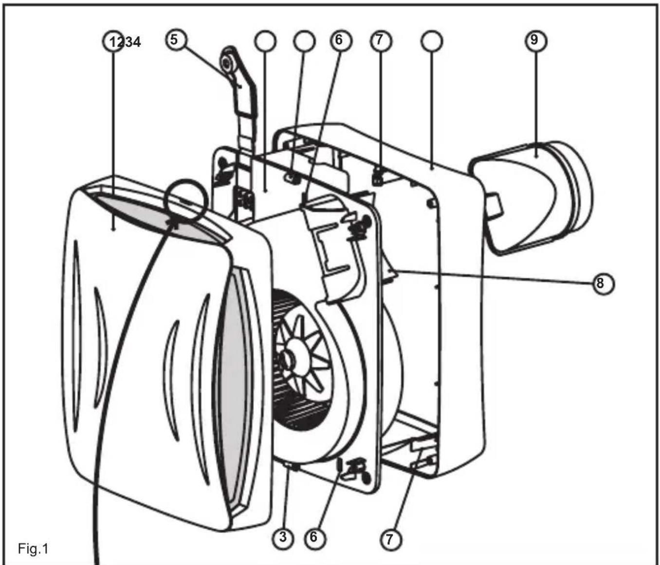

natural_image
Diagram showing a screwdriver inserted into a component, with arrows indicating direction of movement (no text or symbols)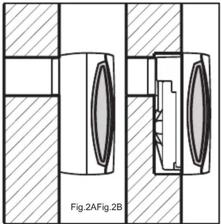
natural_image
Technical diagram showing two cross-sectional views of a mechanical component, labeled Fig.2A and Fig.2B (no text or symbols on the diagram itself)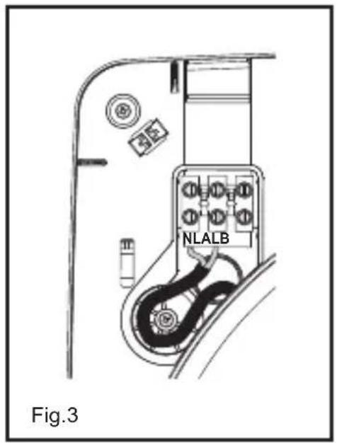

natural_image
Technical line drawing of two mechanical components, one with a dial indicator and the other showing internal blades and mounting holes (no text or symbols)
EBB-T
Fig.7A
Fig.7B

EBB-HT
Fig.8A
Fig.8B


ESPAÑOL EXTRACTORCENTRÍFUGOEBB
EBBseriesextractorhavebeenmanufactured according to strict production and quality control standard such as ISO9001. All the components have been verified and all the devices have been tested following assembly.
Werecommendyoutochéckthefollowingpoints whenyoureceivethisextractor:
1-Makesureyouhavereceivedtherightmodel
2-Makesurethatthedataonthenameplateare appropriatetoyourneeds:voltage,frequency, speed,etc.
SAFETYRECOMMENDATIONS
The installation must be carried out in accordance with current regulations since each country.
-Theinstallationmustbecarriedoutbya qualifiedprofessional.
-Theelectrical installation must incorporate an omnipolarswitch with an opening between contact so far least 3 mm, appropriate for the load and complying with current standards.
-Inbathrooms, the device must be installed outside each of any person taking a shower or abath and these switch must be installed outside the bathroom.
-Donotusethesefansinexplosiveorcorrosive atmospheres. If the EBBisworking in a kitchen where there is a boiler or any other kind of combustion device that needs airtowork, check that the air inlet stothekitchen are sufficient.
-Theextractordischargecannotbeconnectedto aconduitfortheevacuationofsmokefrom devicesworkedbygasoranyotherfuel -Intheeventofconsiderablehumidity,youare advisedtoinstallthedischargeconduit horizontally,withaslightoutwardsslant.
INSTALLATION
IMPORTANT: Before proceeding with the installation and connection of the device, makes sure to disconnect the electricity supply.
Figure1A:
1-Frontcover
2-Fanbody
3-Frontcoverclip
4-Baseframe
5-Connectionscover
6-Slots
7-Retainers
8-Deflector
9-Dischargeflange
- EBBseriesfansmustbeinstalledinanareathat isshelteredfrommeteorologicalconditions;they canbeassembledeitherinverticalorhorizontal position.
- Theextractorisdesignedtobeconnectedtoa
100-mmdiameterconduit
-Beforeassembling the device, check that the turbinerotates freely.
Foryoureextractortoworkmoreefficiently:
-Donotuseconduitswhosediameterislessthan 100mm
-Ifaflexibleconduitisused,stretchitoutfully
-Donotplaceelbowsrightattheextractor discharge
-Elbowsshouldhaveaslargearadiusas possible
SurfaceAssembly(fig.2A):
- Makea105-mmdiameterholeinthewallor ceiling, makingsurethatthedevicefitsinthearea youhaveplannedforit.
- Removethefrontcover(1) of the fan body(2) pressing the clips(3) carefully with a small screwdriver (fig. 1B).
- Thefanbody(2)issecuredtothebaseframe (4)bymeansof4screwsand3flanges.To dismantleit,removethe4screwsfromthe cornersandopenthe3flanges(7)byintroducing asmallscrewdriverthroughtheslots(6).
- Using 4 screws and plug that are appropriate for the kind of wall, fix the base frame (4) onto the surface, ensuring that the circular profile of the frame coincides with the opening made, so that the dischargenozzcan be introduced easily subsequently.
- Open the connections cover (5) of the fan body and pas the cable through the hole provided forth this purpose on the bottom of the terminal box.
- Reassemblethefanbody(2)ontothebase frame(4)byintroducingitintotheflangesand securingitwiththe4screws.
- Connecttotheterminalspassingthecable throughasindicatedinfigure.3.
- Follow the electrical diagram applying to the EBB version that is being installed (fig. 5to8).
- Closetheconnectionscover(5)withthe screw.
- Assemble the front cover (1) again, pressing the upper and lower clips and pressing each corner downtoensure that it fits properly in place.
- Turntheextractorontocheckthatitworks properly.
Built-inassembly(fig.2B):
- Usethetemplatetomarkandcutthepanel intowhichthedevicewillbeinstalled.Readthe instructionsgivenonthetemplatecarefully.
- Followsteps1, 2 and 3 of the Surface Assembly Instructions.
- With built-in assembly, the discharge can be directed toward the these side (fig. 4). Todo this, removethed discharge flange (3). Cut the deflector (8) completely and put the discharge flange back in the desired direction.
-
Opentheconnectionscover(5) and passthe cablethrough the hole provided forth this purpose on the bottom of the terminal box.
-
Connecta100-mmdiametertubetothe dischargeflange(9).
-
Secure the fan body (2) using 4 screws and plug st h at a r e a p p r o p r i a t e f o r t h e k i n d o f s u r f a c e.
-
Connecttotheterminals, passingthecable throughasindicatedinfigure3.
-
Follow the electrical diagram applying to the EEB version that is being installed (fig. 5to8)
-
Closetheconnectionscover(5)withthe screw.
-
Assemble the front cover (1) again by tightening the upper and lower clips and pressing each corner to ensure that fits properly in place.
-
Switch the extractor onto check that it is working properly.
ELECTRICALCONNECTION(fig.5to8)
-Beforeworkingonthefan, makesurethatitis fullydisconnectedfromtheelectricitysupply, evenifitisswitchedoff.
-Makesurethatthevoltageandfrequency valuesoftheelectricitysupplyarethesameas thoseindicatedonthenameplateofthedevice (maximumvoltageandfrequencyvariation:5%).
-EBBsareclassII(doubleinsulation)devices anddonotrequireearthconnection
-Followtheconnectionsdiagramapplyingtothe versioninstalled
EBBversion“S”
Basicversionwithtwo-speedmotor, which can also be voltageregulated. For this model proceed according to one of the following diagrams:
Fig.5A-Single-speedoperationwith an independentswitch.
Fig.5B-FSingle-speedoperationusingthesame switchasthelight
Fig.6A-2-speedoperationwithaswitch Fig.6B-OperationwithanREB-typevoltage regulator
EBBversion“T”
Modelsequippedwithtimingjstable timingenablesthedevicetooperateforthetime set,whentheswitchhasbeenturnedoff(fig.7A). Intimermode,theEBBoperatesatslowspeed.
ATTENTION: The device estimated to start up 50 seconds after being switched on, which mean that for the first 50 seconds it does not work.
Fig.7BTimer-basedoperationsothatthedevice startsupbymeansofthesameswitchasthe light.
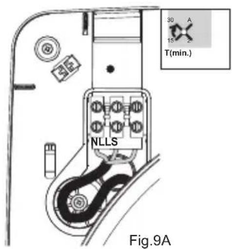
Tosetthistimerfunction(fig.9A), turn the potentiometersituatedbesidetheconnections cover(5).
The device can be set to 4 different timer positions:
AutoPosition :
-Ifthedeviceisusedforlessthan50seconds, thetimingwillnotcomeintooperation
-If the device is used for more than 50 seconds the timing is controlled automatically by the device. It is proportional to the time of use (time of use/x2, with a maximum of 30 minutes).
Position2':Timingsetto2minutes Position15':Timingsetto15minutes Position30':Timingsetto30minutes
EBBversion“HT”
Modelsequippedwithanelectronichumidistat thatcanberegulatedbetween60andthe90% RH(RelativeHumidity%)andwithtimingthatcan besetbetween1and30minutes.
WheninthetimermodetheEBBworksatslow speed.
Recommendations:
- Inordertomodifythefactorysettings, the potentiometerssituatedbesidetheconnections cover(fig.9B)willhavetobeoperated. These potentiometersarefragileandmustbehandled withcare.
-Forcorrecthumiditydetection, the device must be installed in an area in which there is good air circulation.
-Donotchangethehumiditysettingoutsidethe areainwhichthedeviceisinstalled.
Settings:
Theextractorsarepresetto60%RHforhumidity and1 minutefortiming.
-If the humidity level in the area is below 60% RH, the extractor will not start up.
-If the humidity level in the area is above 60% RH, the extractor will start up automatically.
-If the humidity level is always above 90% RH the extractor will operate constantly.
-If you wish to modify these settings, that is, maintain a humidity level of over 60% RH in the area, turn the "potentiometer clockwise.
-If you wish to increase the timersetting; that is, increase the time during which the extractor operates on the humidity level is under the set level, turn the potentiometer. Tmin: clockwise.
ATTENTION: You should not attempt to adjust the extractor settings when the extractor is in timer mode. You must wait until the second time has elapsed before adjusting these settings.
Operation
Case1 : Inautomaticworkingmode(fig.8A) the deviceswitchesonautomaticallyatfastspeed whenthehumiditylevelintheareaisabovethe selectedvalue.Itstopswhenthehumiditylevel dropsbelowthisvalueandwhenthetimesetby thetimerhaselapsed.Whenthedeviceisintimer mode,itworksatslowspeed.
Case2 :Automaticoperationwithpossibilityof turningonthedevicebymeansofthelightswitch (fig.8B).Automaticoperationsimilartocase1but withthedevicewillstartupevenifthehumidity levelintheareaisbelowthesetvalue.Inthis case,whentheswitchisturnedoff(thelightis
switched off), the device continues to operate at slow speed for the length of time set by the timer.
ATTENTION: When the relative humidity level in the area is above the set value, automatic operation prevails over manual operation; that is, the device cannot be turned off by means of the switch.
MAINTENANCE
IMPORTANT: Before carrying out any maintenance operations, make sure to disconnect the electricity supply.
You are advised to remove any dirt that has accumulated in the 4 filters of the front cover (1) at regular intervals. To do so, remove the front cover as indicated in the “INSTALLATION” section and hand wash with warm soapy water. Make sure that the front cover is absolutely dry before putting it back in place.
Clean the other parts with a cloth soaked in mild detergent.
USER INSTRUCTION
This appliance can be used by children aged from 8 years and above and persons with reduced physical, sensory or mental capabilities or lack of experience and knowledge if they have been given supervision or instruction concerning use of the appliance in a safe way and understand the hazards involved. Children shall not play with the appliance. Cleaning and user maintenance shall not be made by children without supervision.
TECHNICAL ASSISTANCE
Should you observe any anomaly in the operation of the device, contact an official authorised service or the seller of the product.
If the device is handled by persons who are not authorised by S&P, the guarantee will be cancelled.
(S&P reserves the right to make changes without prior notice.)
FRANÇAIS AERATÉURCENTRIFUGEEBB
5-AbdeckungderAnschlüsse
6-Nuten
7-Klinken
8-Ablenkplatte
9-Abluftflansch
Montagealsopbouw(Fig.2A)
- ESPAÑOL EXTRACTORCENTRÍFUGOEBB
- SAFETYRECOMMENDATIONS
- INSTALLATION
- Figure1A:
- Foryoureextractortoworkmoreefficiently:
- SurfaceAssembly(fig.2A):
- Built-inassembly(fig.2B):
- ELECTRICALCONNECTION(fig.5to8)
- EBBversion“S”
- EBBversion“T”
- ATTENTION: The device estimated to start up 50 seconds after being switched on, which mean that for the first 50 seconds it does not work.
- EBBversion“HT”
- Recommendations:
- Settings:
- ATTENTION: You should not attempt to adjust the extractor settings when the extractor is in timer mode. You must wait until the second time has elapsed before adjusting these settings.
- Operation
- MAINTENANCE
- USER INSTRUCTION
- TECHNICAL ASSISTANCE
- FRANÇAIS AERATÉURCENTRIFUGEEBB
- Montagealsopbouw(Fig.2A)
Brand : Soler & Palau
Model : EBB
Category : Extraction fan