
EB100N - Extraction fan Soler & Palau - Free user manual and instructions
Find the device manual for free EB100N Soler & Palau in PDF.
| Brand | Soler & Palau |
| Model | EB100N |
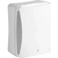
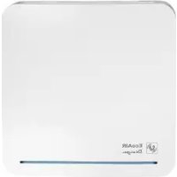
| Product type | Wall or ceiling extractor fan |
| Drilling diameter | 105 mm |
| Duct diameter | 100 mm (standard) |
| Weight | Approximately 1.2 kg |
| Power supply | Single-phase, voltage and frequency as per nameplate (e.g., 230 V ~ 50 Hz) |
| Insulation class | Class II (double insulation); 12V version: Class III |
| Available versions | S (simple), T (adjustable timer 1-30 min), HT (timer + hygrostat 60-90% RH) |
| Low voltage power supply (12V) | Via safety transformer CT-45/12 (not included) |
| Installation | By a qualified professional; comply with local regulations |
| Electrical connection | Switch with contact opening ≥ 3 mm; no earth connection (except transformer) |
| Maintenance and cleaning | Disconnect before intervention; clean with a cloth dampened with mild detergent |
| Safety | Do not insert objects into the grille; do not use without front grille |
| Use | Children from 8 years under supervision; prohibited for persons with reduced capacities without assistance |
| Warranty | Manufacturing defects covered; any unauthorized handling voids warranty |
| Recycling | Packaging and used equipment to be disposed at recycling points |
Frequently Asked Questions - EB100N Soler & Palau
User questions about EB100N Soler & Palau
0 question about this device. Answer the ones you know or ask your own.
Ask a new question about this device
Download the instructions for your Extraction fan in PDF format for free! Find your manual EB100N - Soler & Palau and take your electronic device back in hand. On this page are published all the documents necessary for the use of your device. EB100N by Soler & Palau.
USER MANUAL EB100N Soler & Palau
The EB range extractors have been manufactured to the rigorous standards of production and quality as laid down by the international Quality Standards ISO 9001. All the components have been checked and all the final products have been tested at the end of the manufacturing process.
Please read this instructions booklet carefully before installing or starting up the product. It contains important information on personal and user safety measures to be followed while installing, using and carrying out maintenance work on the equipment.
IMPORTANT INFORMATION
- Check that the apparatus is in perfect condition while unpacking. Any fault or damage caused in origin is covered by the S&P guarantee. Please make sure that the apparatus coincides with the product you have ordered and that the details on the instructions plate fulfil your necessities.
- Installation must only be carried out by qualified persons.
- Make sure that the installation complies with each country's current mechanical and electrical norms.
-
If a ventilator is going to be installed to extract air from premises where a boiler or other combustion apparatus are installed, make sure that the building has sufficient air intakes to assure adequate combustion.
-
The extractor outlet must not be connected to a duct used to exhaust smoke or fumes from any appliance that uses gas or any other type of fuel.
- This appliance can be used by children aged from 8 years and above and persons with reduced physical, sensory or mental capabilities or lack of experience and knowledge if they have been given supervision or instruction concerning use of the appliance in a safe way and understand the hazards involved.
- Children should not play with the product.
- Cleaning and user maintenance shall not be made by children without supervision.
- Do not introduce any object through the protective grille.
- Do not remove the front grille while the fan is in operation or rotation. The extractor must always operate with properly mounted front grille.
INSTALLATION
IMPORTANT: Before installing and wiring the EB, ensure that the main supply is disconnected.
Fig.1: 1- Protection grille 4- Connection terminals cover
2-Fixing screw 5-Cable entry
3- Fan support 6- Slot
The EB can be wall or ceiling mounted, and it can discharge directly to the outside or through a duct (individual or common duct, Fig. 2).
The hole to be made in the wall or the ceiling must be 105mm in diameter. Loosen the screw (2) fix the protection grille (1).

If the installation is made to an individual ducting, use standard ducting of 100 mm diameter. Smaller diameter must not be used. If it is necessary to bend the duct at the discharge of the fan, make the radius as large as possible.
Before fi xing the fan support [3], ensure that there are no obstructions to the airflow, that the shutter mounted at the fan discharge opens easily and that the impeller turns freely.
Fix the fan support to the wall with the 4 plugs and screws supplied in the packaging. Loosen the screws of cover [4] to gain access to the connection terminals. Connect the electrical wiring as follows.
ELECTRICAL CONNECTION
The EB is an extractor designed for a single phase supply, with voltage and frequency as indicated on the rating plate of the unit. The EB models are made Class II (double electrical insulation) and the EB 12V are made Class III and therefore they do not need an earth connection.
IMPORTANT: The safety isolating transformers CT-45/12 used with EB 12V must be earth connected.
The electrical installation must include a double pole switch with a contact clearance of at least 3mm .
The electrical cable must be introduced to the EB through the slot (6) if the wire is within the wall or through the cable entry (5 if the installation is made with a surface mounted cable.
Once the cable has been introduced, proceed to the appropriate electrical wiring depending on the EB model.
EB MODELS S
For these models use the following diagrams:
Fig. 3: To switch the fan through an independent switch.
Fig. 4: Switching the extractor through the light switch.
EB MODELS S (12V~50Hz)
For these models use the CT-45/12 safety isolating transformer:
Fig. 9: To switch the transformer and the extractor through an independent switch.
Fig. 10: Switching the transformer and the extractor through the light switch.
EB MODELS T
Models fitted with an adjustable timer, variable between 1 and 30 minutes. The timer enables the extractor to continue running during the time delay, after the supply has been switched off.
The diagram on Fig. 5 shows how to connect a unit fitted with timer using an independent switch.
The diagram on Fig. 6 shows how to connect a unit fitted with timer using the light switch.
To adjust the timer, turn the potentiometer in the lower part of the fan with a small screwdriver:
To increase the time delay turn it Clockwise (CW).
- To decrease the time delay turn it Counter Clockwise (CCW).
EB MODELS T (12V~50Hz)
For these models use the CT-45/12 safety isolating transformer:
Fig. 11: To switch the transformer and the extractor through an independent switch.
Fig. 12: Switching the transformer and the extractor through the light switch.
EB MODELS HT
This model is provided with an electronic hygrostat which can be adjusted from 60 to 90% RH (% relative humidity).
The two functions, timer and humidity control, are independent The adjustments are carried out with the potentiometer in the lower part of the appliance (fi g.7).
To adjust the timer, turn the right potentiometer with a small screwdriver:
- To increase the time delay turn it Clockwise (CW).
- To decrease the time delay turn it Counter Clockwise (CCW).
To adjust the humidity level above which the fan will operate automatically, turn the left potentiometer with a small screwdriver.
Operation
The timer will operate when the Switch (independent switch or light switch) is switched off.
The hygrostat causes the extractor to operate automatically when the humidity

level in the room is higher than the level selected with the potentiometer.
Likewise, the extractor will stop automatically when the humidity level drops below the selected level.
The diagram on fi g.7 shows how to connect the unit through an independent switch.
The diagram on fig.8 shows how to connect the unit through the light switch.
EB MODELS HT (12V~50Hz)
For these models use the CT-45/12 safety isolating transformer:
Fig. 13: To switch the transformer and the extractor through an independent switch.
Fig. 14: Switching the transformer and the extractor through the light switch.
MAINTENANCE
IMPORTANT: Before manipulating the ventilator, make sure it is disconnected from the mains supply even if it has previously been switched off. Prevent the possibility of anyone else connecting it while it is being manipulated. The extractor needs only a periodical cleaning using a cloth lightly impregnated with a soft detergent.
AFTER SALES SERVICE
The extensive network of S&P Official Services guarantees good technical assistance all over Spain. If you observe any anomalies in the convector, please contact any of the above mentioned Services, where you can get the correct advice. Any modification that is not strictly necessary for the installation of the device and carried out by persons outside of the S&P Official Services will invalidate the guarantee.
For any queries regarding the S&P Products go to the S&P After Sales Service network if is Spanish territory or your dealer in the world. For the nearest location you can consult the webpage: www.solerpalau.com.
RECYCLING
EEC Standards, together with the responsibility we should assume with future generations in mind, oblige us to recycle all the materials we can. Therefore, please deposit all left-over material and packaging in their corresponding recycling containers and hand in the replaced machines to the nearest handler of this type of waste product.
S&P reserves the right to alter specifications without notice.
FRANÇAIS
RECOMMANDATIONS IMPORTANTES
3- Support 6-Passe-cable arrriere

The EB models are made Class II (double electrical insulation) and the EB 12V are made Class III and therefore they do not need an earth connection.
IMPORTANT: The safety isolating transformers CT-45/12 used with EB 12V must be earth connected.
The electrical installation must include a double pole switch with a contact clearance of at least 3mm .
For these models use the CT-45/12 safety isolating transformer:
Fig. 9: To switch the transformer and the extractor through an independent switch.
Fig. 10: Switching the transformer and the extractor through the light switch.
MODELLENS EB-T
For these models use the CT-45/12 safety isolating transformer:
Fig. 11: To switch the transformer and the extractor through an independent switch.
Fig. 12: Switching the transformer and the extractor through the light switch.
MODELLEN EB-HT
For these models use the CT-45/12 safety isolating transformer:
Fig. 13: To switch the transformer and the extractor through an independent switch.
Fig. 14: Switching the transformer and the extractor through the light switch.
ONDERHOUD
- IMPORTANT INFORMATION
- INSTALLATION
- ELECTRICAL CONNECTION
- IMPORTANT: The safety isolating transformers CT-45/12 used with EB 12V must be earth connected.
- EB MODELS S
- EB MODELS S (12V~50Hz)
- EB MODELS T
- EB MODELS T (12V~50Hz)
- EB MODELS HT
- Operation
- EB MODELS HT (12V~50Hz)
- MAINTENANCE
- AFTER SALES SERVICE
- RECYCLING
- FRANÇAIS
- RECOMMANDATIONS IMPORTANTES
- MODELLENS EB-T
- MODELLEN EB-HT
- ONDERHOUD
Brand : Soler & Palau
Model : EB100N
Category : Extraction fan