Neocut 105 - Slicer GYS - Free user manual and instructions
Find the device manual for free Neocut 105 GYS in PDF.
| Product type | Three-phase plasma cutter |
| Brand | GYS |
| Model | Neocut 105 |
| Power supply | Three-phase 400 V ±15%, 50-60 Hz |
| Max cutting current | 105 A |
| Power input (I1eff) | See nameplate |
| Required air pressure | 5 to 9 bars |
| Minimum air flow | 305 L/min |
| Protection | IP23 |
| Operating temperature | -10 °C to +40 °C |
| Storage temperature | -20 °C to +55 °C |
| Max humidity | 50 % at 40 °C, 90 % at 20 °C |
| Max altitude | 1000 m |
| Functions | Cutting, gouging, marking on all metals |
| Cutting modes | Cut, locked cut, gouging, locked gouging, slotted sheets, marking |
| Current adjustment | Via knob on HMI |
| Pressure adjustment | Automatic or manual via HMI |
| Included torch | MT125 (6 m or 12 m depending on version) |
| Included accessories | Plasma torch, ground clamp, power cable, integrated air filter |
| Maintenance | Dust removal, air filter draining, checking connections and consumables |
| Safety | Thermal protection, overvoltage, undervoltage, phase loss, torch and consumable detection |
| Warranty | 2 years (parts and labor) according to conditions |
| Repairability | Spare parts available via GYS after-sales service |
| EMC standards | Class A, compliant with IEC 61000-3-11 |
Frequently Asked Questions - Neocut 105 GYS
User questions about Neocut 105 GYS
0 question about this device. Answer the ones you know or ask your own.
Ask a new question about this device
Download the instructions for your Slicer in PDF format for free! Find your manual Neocut 105 - GYS and take your electronic device back in hand. On this page are published all the documents necessary for the use of your device. Neocut 105 by GYS.
USER MANUAL Neocut 105 GYS
Three-phase plasma cutter
INSTALLATION - FONCTIONNEMENT PRODUIT
| NEOCUT 105 NEOCUT 125 Ref. 063044 Ref. 063112 Ref. 067431 Ref. 067448 | ||||
| 4 m | ✓ | ✓ | ✓ | ✓ |
| raccords pneumatiques | ✓ 8 mm + 10 mm 8 m | ✓ m + 10 mm 8 mm + | ✓ 10 mm 8 mm + 10 mm | ✓ |
| 6 m | - | ✓ | ✓ | |
| kit de démarriage | - | ✓ | ✓ | |
ANOMALIES, CAUSES, REMÉDES
Read and understand the following safety instructions before use.
Any modification or updates that are not specified in the instruction's manual should not be undertaken.
The manufacturer is not liable for any injury or damage due to a non-compliance with the instructions featured in this manual.
In the event of problems or uncertainties, please consult a qualified person to handle the installation properly.
ENVIRONMENT
This equipment must be used for cutting operations in accordance with the limits indicated on the descriptive panel and/or in the user manual. Safety instructions must be followed. In case of improper or unsafe use, the manufacturer cannot be held liable.
This equipment must be used and stored in a room free from dust, acid, flammable gas or any other corrosive agent. Operate the machine in an open, or well-ventilated area.
Operating temperature:
Use between -10 and +40^ (+14 and +104^)
Storage between -20 and +55^ (-4 and 131^ ).
Air humidity:
Lower or equal to 50% at 40^ (104^)
Lower or equal to 90% at 20^ (68^)
Altitude:
Up to 1000 meters above sea level (3280 feet).
INDIVIDUAL PROTECTION & OTHERS
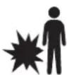
Cutting can be dangerous and cause severe injuries.
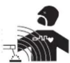
Cutting exposes individuals to a dangerous source of heat, arc rays, electromagnetic fields (special precautions need to be taken by people that have a pacemaker), risk of electrocution, noise and gas fumes.
To protect oneself as well as others, ensure the following safety precautions are taken:

In order to protect you from burns and radiations, wear clothing without turn-ups or cuffs. These clothes must be insulating, dry, fireproof, in good condition and cover the whole body.

Wear protective gloves which provide electrical and thermal insulation.

Use sufficient cutting protective gear for the whole body: hood, gloves, jacket, trousers...(varies depending on the application/ operation) Protect the eyes during cleaning operations. Contact lenses are prohibited during use.
It may be necessary to install fireproof welding curtains in order to protect against safety hazards such as arc rays, weld spatters and sparks.
Ensure that people around the cutting area do not look at the arc or the molten metal and wear protective clothes.

Ensure ear protection is worn by the operator if the work exceeds the authorised noise limit (the same applies to any person in the cutting area).
Keep hands, hair and clothes away from moving parts such as fans, and motors.
Never remove the safety covers from the cooling unit when the machine is plugged in. The manufacturer is not liable for any injury or damage caused due to non-compliance with the safety precautions.

Parts that have previously been cut will be hot and may cause burns if touched. If maintenance of the torch is required, ensure that it is given sufficient time to cool down by waiting at least 10 minutes. When using a water-cooled torch, make sure that the cooling unit is switched on to avoid any burns that could potentially be caused by the liquid.
It is important to secure the working area before leaving it to ensure protection of the goods and the safety of people.
WELDING FUMES AND GAS

The fumes, gas and dust generated by cutting are a potential health hazard. It is mandatory to ensure adequate ventilation and/or extraction to keep fumes and gas away from the work area. Using an air fed welding helmet is recommended in case of insufficient ventilation in the workplace.
Check that the air supply is effective by referring to the recommended safety regulations.
When cutting in small areas, operators must be supervised from a safe distance. Cutting certain materials containing lead, cadmium, zinc, mercury or beryllium can be particularly hazardous. It is also recommended to degrade the parts before cutting them.
Gas cylinders must be stored in an open or ventilated area. They must be stored vertically and held by a support or trolley to limit the risk of fall. Do not cut in areas where grease or paint are stored.
FIRE AND EXPLOSION RISKS

Protect the entire working area and ensure that flammable items are stored at a distance of at least 11 meters. Fire extinguishing equipment must be kept in close proximity when cutting materials.
Be careful of weld spatter and sparks, even through cracks. If not careful then this could potentially lead to a fire or an explosion.
Keep people, flammable materials/objects and containers that are under pressure at a safe distance.
Cutting in containers or pipes should be avoided and, if they are open, then flammable or explosive materials must be removed (oil, fuel, gas...). Grinding operations should not be carried out close to the power supply or flammable materials.
ELECTRICAL SAFETY

The electrical mains used must have an earth terminal. Use the recommended fuse size. An electric shock could cause serious injuries or potentially even deadly accidents.
Do not touch any live part of the machine (inside or outside) when it is plugged in (Torches, cables, clamps) because they are connected to the cutting circuit.
Before opening the device, it is imperative to disconnect it from the mains and wait 2 minutes, so that all the capacitors are discharged. Do not touch the torch or electrode holder and earth clamp at the same time.
Damaged cables and torches must be changed by a qualified technician. Make sure that the cable cross section is adequate with the usage (extensions and welding cables). Always wear clothing that is dry and in good condition in order to shield yourself from the cutting circuit. Wear insulating shoes, regardless of the workplace/environment in which you work in.
EMC MATERIAL CLASSIFICATION

This Class A machine is not intended to be used on a residential site where the electric current is supplied by the domestic low-voltage power grid. There may be potential difficulties in ensuring electromagnetic compatibility at these sites, due to conducted interferences as well as radiation.

This equipment does not comply with IEC 61000-3-12 and is intended to be connected to private low-voltage systems interfacing with the public power grid only at the medium- or high-voltage level. If connected to a public low-voltage power grid, the installer or user of the machine has to ensure, by checking with the network operator, that the device can be connected.
This equipment complies with the IEC 61000-3-11 standard.
ELECTROMAGNETIC INTERFERENCES
The electric current flowing through any conductor causes electrical and magnetic fields (EMF). The cutting current generates an EMF around the cutting circuit and the cutting equipment.
The EMF electromagnetic fields can interfere with certain medical implants, such as pacemakers. Protective measures must be taken for people having medical implants. For example, by restricting access to passers-by or conducting an individual risk evaluation for the users.
All users should take the following precautions in order to minimise exposure to the electromagnetic fields (EMF) generated by the cutting circuit:
- position the cutting cables together - if possible, attach them;
- keep your head and upper body as far as possible from the cutting circuit;
- never wrap the cable around your body;
- Never position your body between the cables. Hold both cutting cables on the same side of your body;
- Connect the earth clamp as close as possible to the area being cut;
- do not work too close to, do not lean and do not sit on the cutting machine;
- do not cut when you're carrying the machine.

People wearing pacemakers are advised to consult their doctor before using this device.
Exposure to electromagnetic fields while welding may have other health effects which are not yet identified.
RECOMMENDATIONS FOR WELDING AREA ASSESSMENT AND CUTTING
General points
The user is responsible for the installation and use of the arc cutting equipment according to the manufacturer's instructions. If electromagnetic disturbances are detected, the user is responsible for resolving the situation with the manufacturer's technical support. In certain cases, this corrective action may be as simple as earthing the cutting circuit. In other cases, it may be necessary to construct an electromagnetic shield around the cutting power source and around the entire piece by fitting input filters. In all cases, electromagnetic interferences must be reduced until they are no longer an issue.
Cutting area assessment
Before installing the machine, the operator must evaluate the possible electromagnetic problems that may arise in the area where the installation is planned. The following elements should be considered:
a) the presence (above below and next to the arc cutting machine) of other power cables, remote cables and telephone cables;
b) television transmitters and receivers;
c) computers and other hardware
d) critical safety equipment such as industrial machine protection;
e) the health and safety of the people in the area such as people with pacemakers or hearing aids;
f) calibration and measuring equipment;
g) the isolation of other pieces of equipment which are in the same area.
The operator has to ensure that the devices and equipment used in the same area are compatible with each other. This may require extra precautions;
h) the time of day during the cutting or other activities have to be performed.
The dimension of the cutting area that has to be considered depends on the size and shape of the building and the type of work undertaken. The area taken into consideration might go beyond the limits of the installation.
Cutting installation assessment
Besides the welding area, the assessment of the arc cutting system installation itself can be used to identify and resolve cases of disturbances The assessment of emissions must include in situ measurements as specified in Article 10 of CISPR 11. In situ measurements can also be used to confirm the effectiveness of mitigation measures.
RECOMMENDED METHODS TO REDUCE ELECTROMAGNETIC EMISSIONS
a. National power grid: the plasma cutting machine must be connected to the national power grid in accordance with the manufacturer's recommendation. In case of interference, it may be necessary to take additional precautions such as the filtering of the power supply network. Consideration should be given to shield the power supply cable in a metal frame or equivalent from a permanent cutting installation. It is necessary to ensure the electrical continuity of the frame along its entire length. The frame should be connected to the cutting machine to ensure good electrical contact between the conduct and the casing of the cutting machine.
b. Maintenance of the arc cutting equipment: the arc cutting machine should be subject to a routine maintenance check according to the recommendations of the manufacturer. All accesses, service doors and covers should be closed and properly locked when the arc welding equipment is on. The arc cutting equipment must not be modified in any way, except for the changes and settings outlined in the manufacturer's instructions. The spark gap of the arc starts and arc stabilization devices must be adjusted and maintained according to manufacturer's recommendations.
c. Cutting cables: cables must be as short as possible, close to each other and close to the ground, if not on the ground.
d. Equipotential bonding: consideration should be given to bond all metal objects in the surrounding area. However, metal objects connected to the workpiece increase the risk of electric shock if the operator touches both the metal parts and the electrode. It is necessary to insulate the operator from such metal objects.
e. Earthing of the metal part to be cut : When the part is not earthed - due to electrical safety reasons or because of its size and its location (e.g. ship hulls or metallic building structures), the earthing of the part can, in some cases but systematically, reduce emissions. It is preferable to avoid the earthing of parts that could increase the risk of injury to the users or damage other electrical equipment. If necessary, it is appropriate that the earthing of the part is done directly, but in some countries that do not allow such direct connection, it is appropriate for the connection to be made with a capacitor selected according to national regulations.
f. Protection and shielding: The selective protection and shielding of other cables and devices in the area can reduce perturbation issues. The protection of the entire cutting area can be considered for specific situations.
TRANSPORT AND TRANSIT OF THE CUTTING MACHINE

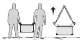
The machine is equipped with two handles to facilitate transport, which requires two people. Be careful not to underestimate the weight of the machine. The handle cannot be used to lift the product.
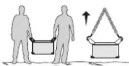
Do not use the cable or torch to move the machine. The cutting equipment must be moved in an upright position.
Do not place/carry the unit over people or objects.
EQUIPMENT INSTALLATION
- Put the machine on the floor (maximum incline of 10^ )
- Provide an adequate area to ventilate the machine and access the controls.
This equipment must be used and stored in a place protected from dust, acid, gas or any other corrosive substance.
The equipment protection is rated IP23 meaning that: - sensitive parts of the equipment are protected from objects with a diam >12.5 mm and,
- it is protected again rainfall with a 60^ vertical incline.
The equipment can be used outside in accordance with the IP23 protection certification.
Power cables, extension leads and welding cables must be fully uncoiled to prevent overheating.

The manufacturer does not accept any liability in relation to damages caused to objects or harm caused to persons as the result of incorrect and/or dangerous use of the machine.
MAINTENANCE / RECOMMENDATIONS


-
Maintenance should only be carried out by a qualified person. A yearly maintenance is recommended.
-
Ensure the machine is unplugged from the mains, and then wait 2 minutes before carrying out maintenance work. Inside,
voltages and currents are high and dangerous.
- Remove the casing 2 or 3 times a year to remove any excess dust. Take this opportunity to have the electrical connections checked by a qualified person, with an insulated tool.
- Regularly check the condition of the power supply cable. If the power cable is damaged, it must be replaced by the manufacturer, its after sales service or an equally qualified person to prevent danger.
- Ensure the vents of the device are not blocked to allow adequate air circulation.
- Check that the torch does not have any cracks or exposed wires.
- Check that the consumables are installed properly and not worn.
Air filter maintenance :
Purge of the filter tank :
- Unplug the air supply.
- Loosen the valve in the lower part of the filter tank by turning it anticlockwise.
- Push the tap upwards to drain the water from the tank.
- Tighten the valve at the bottom of the filter tank by turning it clockwise.
Removing the filter element :
- Disconnect the air supply.
- Take hold of the tank and unscrew it from the body by turning it anticlockwise.
- The filter element (white) can be blown out or replaced depending on its condition.
Reassembling the filter element : - Put the filter element back in the tank, check the presence of the O-ring in the upper part.
- Screw the tank back onto the body by turning it clockwise.
INSTALLATION - PRODUCT OPERATION
Only qualified personnel authorised by the manufacturer should perform the installation of the welding equipment. During the installation, the operator must ensure that the machine is disconnected from the mains.
MACHINE SUPPLIED WITH
| NEOCUT 105 NEOCUT 125 Ref. 063044 Ref. 063112 Ref. 067431 | Ref. 067448 | |||
| 4 m | ✓ | ✓ | ✓ | ✓ |
| Pneumatic fittings | ✓ 8 mm + 10 mm 8 mm | ✓ + 10 mm 8 mm + 10 mm | ✓ mm + 10 mm | ✓ |
| 6 m | - | ✓ | ✓ | |
| Starting kit | - | ✓ | ✓ | |
Accessories supplied with the generator are designed to be used on this machine only.
DESCRIPTION
NEOCUT is a three-phase Plasma cutting & gouging machine, it will allow:
- Cutting on all metal types
- Gouging on all metal types
- Marking on all metal types
These 3 processes require the use of appropriate consumables as well as compressed air or nitrogen.
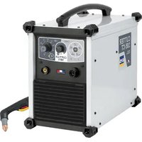
EQUIPMENT DESCRIPTION (FIG. 1 - PAGE 2)
1- Display screen 7- Transport handles.
2- Adjustment knob 8- Replacement for pneumatic connector
3-Earth clamp connection socket 9-Power supply cable
4- Plasma torch connector
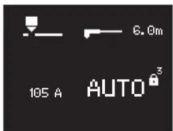
5- CNC 1 analog (optional, ref. 039988) or CNC 2 digital (optional, ref. 064737) connector installation door
6- Installation door for digital retrofit CNC 3 connector (option, ref. 068957)
10- On/off switch
11- Filter
POWER SUPPLY / POWER UP
- The NEOCUT 105 is supplied with a 32A plug of type EN 60309-1.
- The NEOCUT 125 is supplied without plug, it is recommended to use a 63A plug of type EN 60309-1.
These current sources should only be used on a four-wire, three-phase 400V (50-60 Hz) electrical installation with a neutral connected to earth. - The effective absorbed current (I1eff) is indicated on the device, for maximum operating conditions. Check that the power supply and its protections (fuse and/or circuit breaker) are compatible with the current required in use. In some countries, it may be necessary to change the plug to allow use at maximum conditions.
- The machine is designed to work on a 400V + / - 15% power supply. If the input voltage is below 340Veff or above 460Veff, the machine goes into protection and the screen displays an error code.
- Power up the machine by setting the main on / off switch (FIG 1-10) to I position, and stop it by setting it on the 0 position.
Warning! Never disconnect the power supply while the machine is operating.
CONNECTION TO A GENERATOR
The machine can work with generators as long as the auxiliary power matches these requirements:
- The voltage must be AC, always be greater than 400Vac ±15%, and the peak voltage below 700V,
- The frequency must be between 50 and 60Hz
It is imperative to check these requirements, as many generators generate high voltage peaks that can damage these machines.
USE OF EXTENSION LEADS
All extension leads must have an adequate size and section, relative to the voltage of the machine. Use an extension lead that complies with national safety regulations.
| Voltage input Extension lead section (<45m) | ||
| NEOCUT 105 | 400 V | 4 mm² |
| NEOCUT 125 6 m² | ||
AIR SUPPLY
The air supply can come from a compressor or high-pressure bottles. A high-pressure manometer must be used on any type of air supply and must be able to transport the gas to the plasma cutter. These machines come with an integrated air filter (5 m) , but an extra filtering system can be necessary depending on the quality of the air supply (optional impurities filter, ref. 039728).

If the supplied air is of low quality, the cutting speed is reduced, the cutting quality deteriorates, the maximum cutting capacity decreases and the life cycle of the consumables is reduced.
For best performance, the compressed air must comply with the standard ISO8573-1, class 1.2.2. The maximum steam point must be - 40^ . The maximum quantity of oil (aerosol, liquid and steam) must be 0.1mg / m3 .
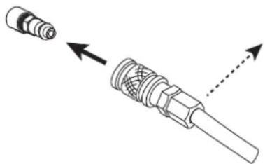
Connect the gas supply to the power source using an inert gas pipe with an internal diameter of 9.5mm and a quick release connector.

The pressure must not exceed 9 bars, or the filter tank could explode.
The recommended input pressure during air circulation is 5 to 9 bars with a minimum debit of 305L / min
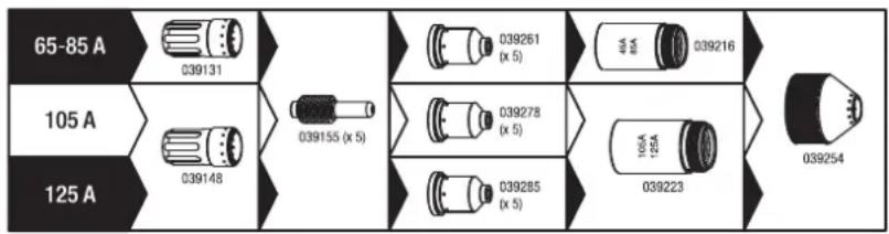
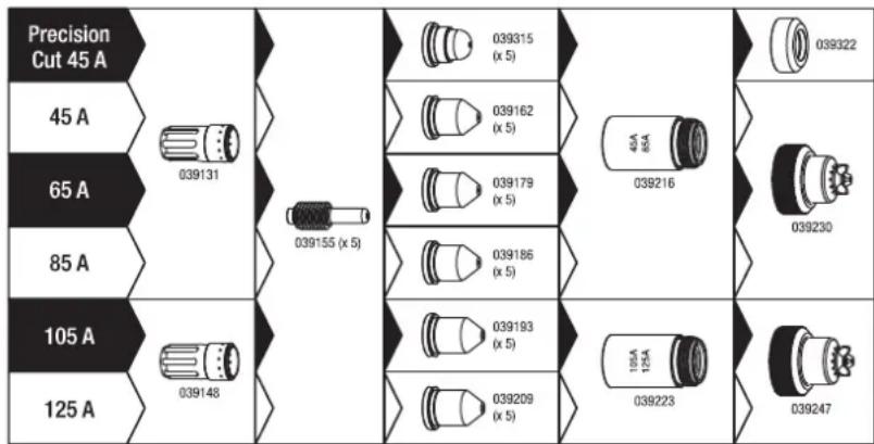
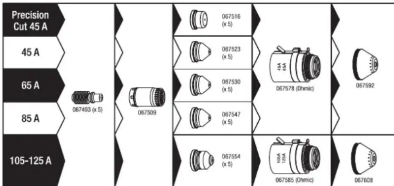
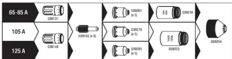
CHOICE OF CONSUMABLES
- Manual cutting with torch MT 125 (6 m : ref. 039506, 12 m : ref. 039513) :
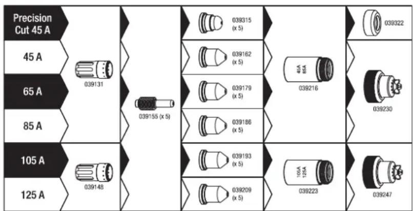
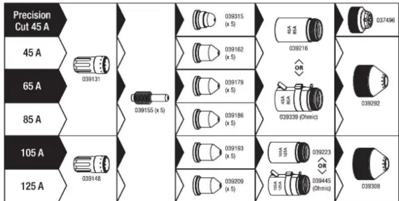
Automatic cutting with torch AT 125 (6 m : ref. 038479, 12 m : ref. 039520, 15 m : ref. 069787, 20 m : ref. 069794) :

Automatic cutting with torch AT 160 (6 m : ref. 067479, 12 m : ref. 067486, 15 m : ref. 069800, 20 m : ref. 069817) :
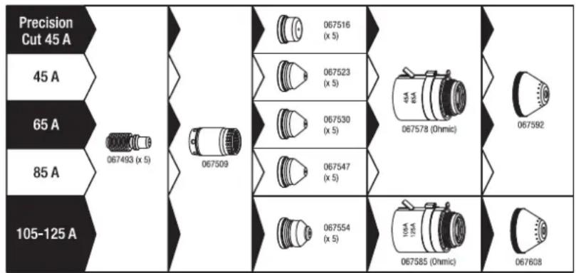
Gouging with torch MT 125 (6 m : ref. 039506, 12 m : ref. 039513) :
CUTTING CURRENT SETTINGS

In order to obtain the expected performance and to guarantee a long lifetime for the consumables, make sure the current is set in accordance with the value indicated on the consumable (e.g. 45A = 45 amps).
Adjustment is simply done using the dial on the main screen.
AIR PRESSURE ADJUSTMENT
The NEOCUT is equipped with an electronically controlled pressure regulator, the pressure is adjusted via the HMI (see following pages). In order to obtain optimal performance and service life of the consumables, it is very important :
- To define the right torch length
- To use the adapted mode for the chosen consumables
- To use the appropriate current for the chosen consumables
- Leave the pressure setting on «auto».
It is recommended to check that the parameters entered on the HMI are in line with the actual configuration, especially in the case of:
- Connection point or pneumatic installation changes
- Torch length change
- Consumable type change
- Doubt.
It is possible to check the pneumatic circuit using the «air test» function, this allows, among other things, to check whether the pressure supplied by the compressor is sufficient (see following pages).
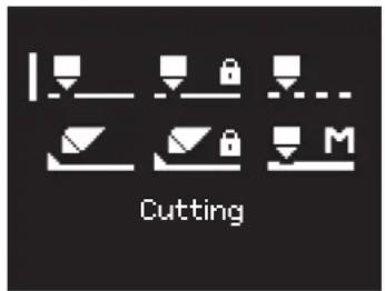
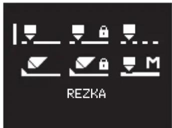
CUTTING MODE CHOICE
| Cutting / cutting with locked trigger Use one of these two modes to perform your cutting work on solid sheet metal. Pull the trigger to create the arc, and release it to stop or «unlock» (the arc stops by itself). For long cuts it is possible to use the locked trigger mode, in which case the trigger can be released during cutting. This mode prevents fatigue and keeps your hand a little further away from the cutting area. | |
| Gouging / gouging with locked trigger Use one of these two modes to perform your gouging work. Pull the trigger to create the arc, and release it to stop or «unlock» (the arc stops by itself). For long cuts it is possible to use the locked trigger mode, in which case the trigger can be released during cutting. This mode prevents fatigue and keeps your hand a little further away from the cutting area. | |
| Cutting of perforated metal sheets Use this mode to perform cutting work on perforated metal sheets that require repetitive cutting stops / restarts. This is a cutting mode where the arc recharges itself as long as the trigger is held down. This mode is more comfortable to use, as it avoids constant pull and release of the trigger. | |
| Marking out This mode, compatible with all cutting consumables, operates at low current and allows surface marking of sheet metal. Particularly useful for automated cutting to record for example references, bundle numbers... this mode is also accessible with a manual torch. |
FIRST START UP
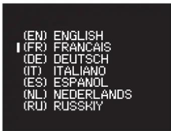
At first startup, the machine will ask you to configure the following parameters:
| 1 | (EN) ENGLISH I (FR) FRANCAIS (DE) DEUTSCH (IT) ITALIANO (ES) ESPANOL (NL) NEDERLANDS (RU) RUSSKIY | 2 | Im. /bar ft. /psi | |
| Language Units (m./bar or ft./psi) | ||||
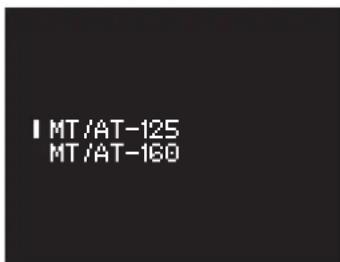
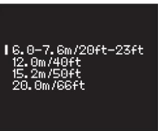
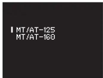
| 3 | IMT/AT-125 MT/AT-160 | 4 | 16.0-7.6m/20ft-23ft 12.0m/40ft 15.2m/50ft 20.0m/66ft | 3-4: Important setting for the correct operation of the product. This data is used by the power source to calculate and apply the optimum operating pressure. |
| Torch model (NEOCUT 125 only) | Torch length | |||
Rotating the scroll wheel moves the cursor in front of the desired selection, pressing the scroll wheel validates the selection.
Note: In the event of an input error, these parameters can be changed (see Setup menu).
HMI NAVIGATION
SCROLL WHEEL USE


Turning the scroll wheel allows
- an adjustment of a digital parameter (current, pressure)
- moving the cursor to make a selection
Pressing the scroll wheel
- allows to confirm a selection (pointed by the cursor)
- access the toolbar from the main screen or from the pressure setting screen
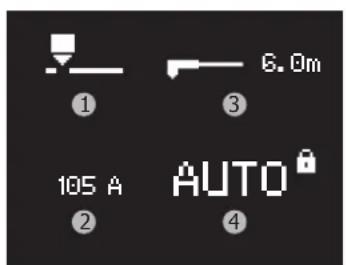
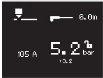
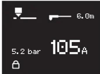
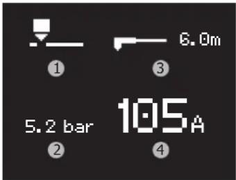
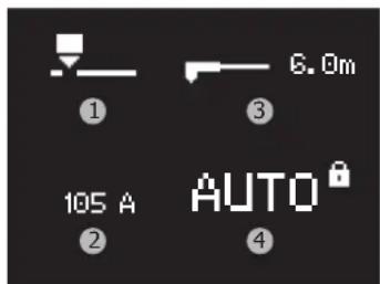
MAIN SCREEN (CURRENT SETTING):
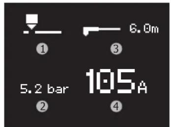
This screen is displayed as soon as the machine is started:
1-Operating mode
2- Current pressure*
3- Selected torch length
4-Current
The current setting is made directly from this screen.
*An arrow pointing up or down may appear to the right of the pressure when the pressure has been incorrectly altered by the user, the arrow disappears when the set pressure is optimal or the pressure setting is set in «auto» mode.
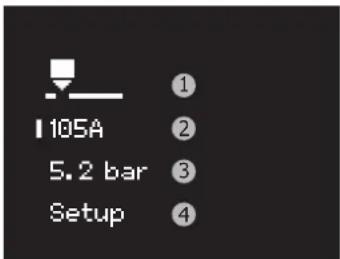
TOOLBAR (ACCESS VIA SCROLL WHEEL)
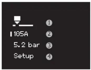
1- Access to the mode selection screen
2- Access to the main screen (current setting)
3- Accessing the pressure adjustment screen
4- Access to the Setup menu
MODE SELECTION
6 modes are available. To make the right choice, please refer to the chapter «mode selection».
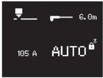
PRESSURE ADJUSTMENT
By default, the screen looks like this:
1-Operating mode
2-Current
3-Torch length
4-Pressure*
*Pressure is automatically locked as default (indicated by the inscription AUTO and the closed padlock): the machine takes care of setting the right pressure value according to various parameters (such as current, mode, torch length).
To switch the pressure setting to manual mode, a long press on the scroll wheel is required: a countdown will start next to the padlock.
Releasing the scroll wheel during the countdown cancels the pressure unlocking action.
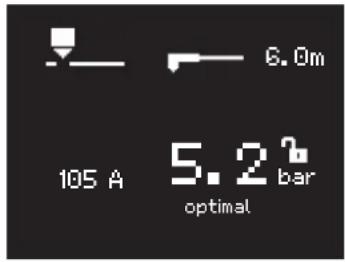
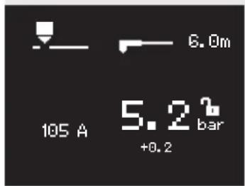
At the end of the countdown, the following screen will appear:
- the padlock is open (symbolizing that the adjustment is possible)
-
the current pressure is displayed (the value corresponds to the value used in automatic mode)
-
A bar-graph with a value gives the trend (the text «optimal» is displayed when the chosen value corresponds perfectly to the value that would be used in automatic mode).
Example of a pressure setting higher than the optimum value of +0.2 bar To return to automatic setting, press and hold down the scroll wheel: a countdown will start next to the padlock.
At the end of the countdown, the setting will be in «AUTO» with the padlock locked.
SETUP MENU (access via scroll wheel)
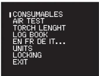
COUNTERS
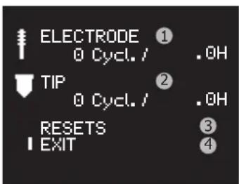
This tool counts the number of cycles and the nozzle and electrode cutting time:
1- Number of cycles and cumulative use time of the electrode
2- Number of cycles and cumulative use time of the nozzle
3-Meter reset menu
4- Go back to the Setup menu
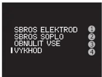
RESETTING THE COUNTERS
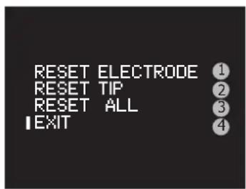
In order to have a representative count, it is necessary to reset the counter(s) of the consumable(s) being replaced.
The counter reset menu offers :
1-Zeroing of the electrode counters
2-Zeroing of the nozzle counters
3-Zeroing of all counters
4- Go back to the previous screen
To carry out a reset, select the desired line by turning the scroll wheel and press and hold down (a countdown is displayed to the right of the selected line), at the end of the countdown the selected line is reset to zero. Releasing the scroll wheel during the countdown cancels the action.
Note: this function is to assist with monitoring the consumables for wear and tear. The user is not obliged to use this function and even less to reset the counters each time the consumable is changed (the machine does not lock up if the number of cycles or operating times is too high).
| GYS | NEOCUT 105 / 125 | EN |
| AIR TEST | ||
| I VALUE =5 bar① INPUT =-,bar② OUTPUT =-,bar③ | This tool allows to force the air out of the power source to: - purge the circuit in case of presence of moisture in the circuit. - check whether the compressor performance is sufficient 1- Test pressure adjustment 2- Display of the pressure at the product inlet 3- Product outlet pressure display Pressing the scroll wheel turns off the air and returns to the Setup menu. | |
| TORCH LENGTH | ||
| I MT/AT-125 MT/AT-160 | Selects the torch model (only for NEOCUT 125) ① Important setting for the correct product operation. This data is used by the power source to calculate and apply the optimum operating pressure. | |
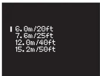
| I 6.0m/20ft 7.6m/25ft 12.0m/40ft 15.2m/50ft | Allows to change the length of the torch ① Important setting for the correct product operation. This data is used by the power source to calculate and apply the optimum operating pressure. | |
| LOG | ||
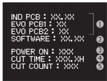
| IND PCB: XX,XX EVO PCB1: XX EVO PCB2: XX SOFTWARE: XX,XX POWER ON: XXX CUT TIME: XXX,XH CUT COUNT: XXX 5 | Displayed in the logbook: 1- Version of the electronic boards 2- Version of the software 3- Number of times the machine was switched on 4- Total cutting time 5- Number of cutting cycle | |
| LANGUAGE | ||
| (EN) ENGLISH I (FR) FRANÇAIS (OE) DEUTSCH (IT) ITALIANO (ES) ESPANDOL (NL) NEDERLANDS (RU) RUSSKIY | Allows you to change the current language | |
| UNITS | ||
| I m. /bar ft. /psi | Allows you to change the current units: - SI units: torch length expressed in meters and pressure in bar - Imperial units: torch length in feet and pressure in PSI | |
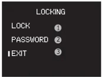
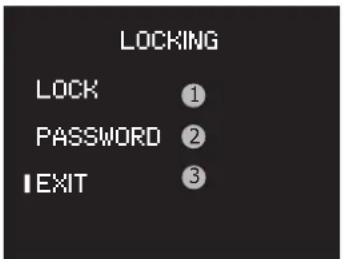
LOCKING
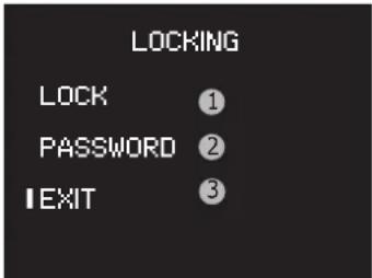
1- Activates the HMI lock and return to the main screen
2- Password change access
3- Exit the menu (without locking)
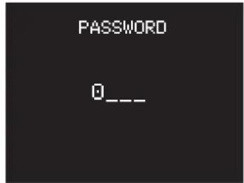
Choosing the password
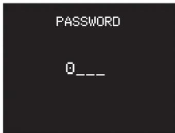
Turn the turn dial to select the first digit and confirm by pressing the wheel. Repeat the process for the remaining three digits.
When the password has been changed, the display will return to the LOCKING menu with the cursor positioned on 'LOCK'. The default password is 0000.
UnlockING
The padlock symbolises that the screen is locked. To unlock the screen, press and hold the turn dial until the countdown is complete (three seconds). Enter the password to unlock the machine.
After incorrectly entering your password three times, the interface will be blocked and will ask for a six digit unlocking code (SUPER PASSWORD). This non-modifiable code is: 314159.
CUTTING SEQUENCE
1- When the trigger is pressed, the pilot-arc starts. It is a low power arc generated between the electrode and the nozzle and it allows the arc to start on the piece of metal to be cut.
2- When the pilot-arc touches the plate, the plasma cutter detects the start. The arc then flows between the electrode and the plate, and the machine increases the current up to the value set by the operator.
3- At the end of cutting (trigger release or unblocking), the arc stops, the air continues to come out for several dozens of seconds to cool the torch and consumables down.
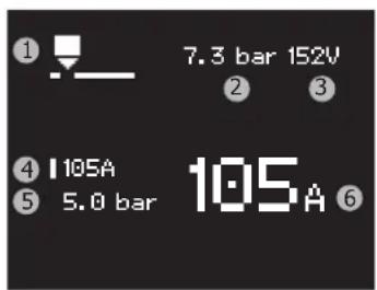
DISPLAYED WHILE CUTTING
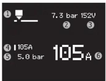
1- Current mode
2-Pressure coming in
3-Arc voltage
4- Current set
5- Pressure going out
6- Current measured
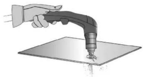
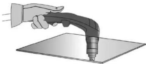
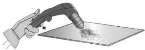
MANUAL CUT FROM THE EDGE OF THE WORKPIECE:
The earth clamp attached to the metal piece, hold the torch pad in perpendicular position (90^) to the end of the workpiece.
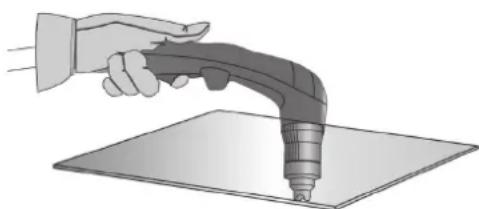
Pull the trigger of the torch to prime the arc until the torch has completely pass through the part.
Once the cutting has started, drag the pad slightly on the metal sheet to continue cutting. Try to maintain a regular rhythm.
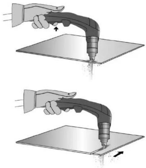
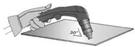
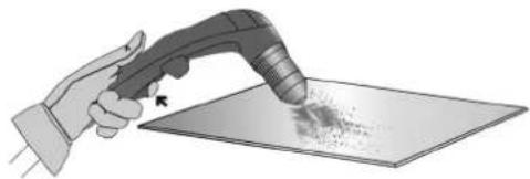
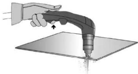
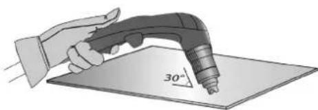
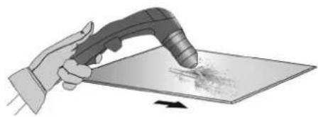
START CUTTING INSIDE THE METAL SHEET:
With the earth clamp attached to the metal piece, maintain the torch at an angle of roughly 30^ to the piece.
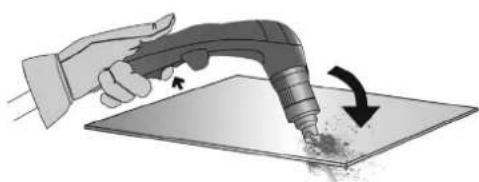
② Press the torch trigger to start the arc while maintaining an angle of 30^ to the part. Slowly rotate the torch towards a perpendicular position (90^) .
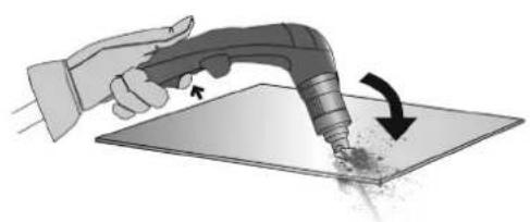
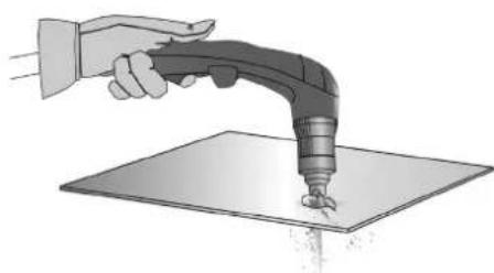
③ Immobilise the torch while keeping the trigger pressed. If the sparks come from below the metal piece, the arc has cut the material.
Once the cutting has started, drag the pad slightly on the metal sheet to continue cutting. Try to maintain a regular rhythm.
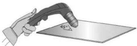
GOGING:
With the earth clamp fastened to the part, keep for torch at a 45^ angle to the piece, while maintaining the special gouging shield roughly 2mm away from the part before starting the torch.
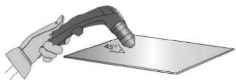
Press the torch trigger before starting the arc while maintaining it at an angle of 45^ to the piece while cutting through the groove
Push the plasma arc in the direction you wish to cut. The distance between the torch shield and the melted metal should be as little as possible in order to avoid premature wear of the consumables or damage to the torch.
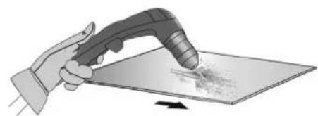
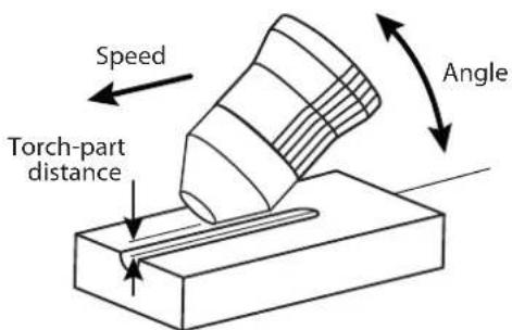
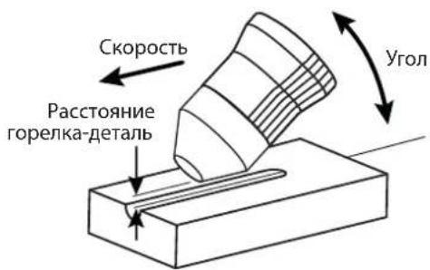
GROOVE SHAPE
You may modify the profile of the groove by adjusting the speed, the angle or the distance of the torch on the metal piece, or the power output on the machine.
CHANGING THE SHAPE OF THE GROOVE
| DESIRED | Width | - | + | + | - | - | + | + | - |
| Depth | - | + | - | + | - | - | + | - | |
| Solutions | Increase the speed | Reduce the speed | Increase the torch-piece distance | Decrease the torch-piece distance | Increase the angle | Reduce the angle | Increase the current | Decrease the current | |
PROTECTION
Safety features prevent the product from working, but are usually due to an operating error, an oversight on the part of the user or an environmental problem. The following table guides the user to solve the problem himself.
| Icon at the onset of safety | Reminder icon | Meaning Solutions | |
| Torch missing | AX | Torch disconnected | Connect a torch. If the problem persists when a torch is connected, check the cables or replace the torch. |
| Unknown torch | AX | Torch unrecognized | Connect a torch compatible with the product. If the problem persists when a torch is connected, check the cables or replace the torch. |
| Nozzle missing | AX | Dismantled nozzle | Check that all consumables are present and screw the nozzle back on. |
| AIR No air | AIR | No air Connect air and check compressor pressure. | |
| AIR Pressure too low | AIR | Inlet pressure insufficient | Connect the compressed air, check the air connection used compatibility, check that the compressor is electrically powered. |
| AIR Input overpressure | AIR | Inlet pressure too high | The inlet pressure is higher than 9 bar. |
| Disconnect the air source, check the compressor pressure, lower the compressor pressure. If necessary, add a pressure regulator between the compressor outlet and the air inlet of the plasma cut-ter. | |||
| If the above icons are displayed, cutting is forbidden but navigation in the HMI is still possible. | |||
| Thermal protection | Le poste est utilisé au-delà de son facteur de marche ou à une température trop élevé ou dans un espace confiné. Laisser-le poste se refroidir, améliorer son aération. | ||
| Overvoltage | Overvoltage | ||
| Undervoltage | Under voltage | If the overvoltage or undervoltage is temporary, the plasma cutter will restart by itself after 15 seconds of non-fault. If this is not the case or if there is no phase, have the electrical installation checked by an electrician. | |
| Missing phase | Phase missing | ||
| Retry | The arcpilot has not established itself | This is probably due to the consumables, check their condition, replace them if necessary. Try again | |
| After 3 unsuccessful attempts, an error code will appear (E05 or E06). | |||
| Trigger pressed | Trigger pressed at start up. | Release the torch trigger to continue. If the trigger is not physically depressed, check the torch cables. | |
ANOMALIES, REASONS, SOLUTIONS
Anomalies result in an immediate shutdown of the plasma cutter, navigation in the HMI is not allowed.
| Logo Code | Messages Possible causes Solutions | ||
| STOP | E00 | NTC | The temperature sensor is damaged or disconnected. |
| E01 | Relay | The power relay does not closed. | |
| E02 | Fan speed | The fan does not function | |
| The fan is not running at the right speed. | |||
| E03 | Faulty air regulator | The pressure regulator fails to regulate the pressure despite an adequate air supply. | |
| E04 | |||
| E05 | Electrode stuck open | No contact between the electrode and the nozzle. | |
| E06 | Electr. stuck closed | The electrode can not retract | |
| E24 | EEPROM/12C | Defect related to the internal memory. | |
| -- Arc stops after 3 seconds of cutting | No current detection in the earth clamp | ||
| - | - | The machine does not switch on. No power supply | |
| - | - | ||
| -- The pilot-arc cuts | out too quickly Used consumables | Check the condition of the consumables and replace if necessary. | ||
| - | - | The arc stops mid-way through cutting | Cutting speed too low on thin sheets | Reduce the current / increase the movement speed. |
| - | - | Contact on the low-quality earth clamp | Check that the earth clamp is connected to the cutting part on a clean area (no rust, paint or grease). | |
| -- Cutting height too | high | Use a cutting pad and keep it in contact with the part to be cut. | ||
| - | - | Pressure Premature wear of consumables | Cutting current inappropriate for consumables used | Refer to the chapter "Setting the cutting current". |
| -- Inappropriate air | Refer to the chapter "Adjusting the air pressure". | |||
| -- Humid air | Purge the air filters from the station and the compressed air network. Add the additional Air filter ref. 039728. |
WARRANTY
The warranty covers faulty workmanship for 2 years from the date of purchase (parts and labour).
The warranty does not cover:
- Transit damage.
Normal wear of parts (eg.: cables, clamps, etc.). - Damages due to misuse (power supply error, dropping of equipment, disassembling).
- Environment related failures (pollution, rust, dust).
In case of failure, return the unit to your distributor together with:
- The proof of purchase (receipt etc ...)
- A description of the fault reported.
| NEOCUT 105 NEOCUT 125 Ref. 063044 Ref. | 063112 Ref. 067431 | Ref. 067448 | ||
| 4 m | ✓ | ✓ | ✓ | ✓ |
| conectores neumáticos | ✓ 8 mm + 10 mm 8 mm | ✓ + 10 mm 8 mm + 10 mm | ✓ 8 mm + 10 mm | ✓ |
| 6 m | - | ✓ | ✓ | |
| kit de inizio | - | ✓ | ✓ |
I3MeHeHn I pEmoHT, He yka3aHHbE B 3ToI INHCTpyKcun, He DoJXhbl 6bIT bpeDpNHrTbI.
IpnH3BODHTeH He HecET OTBeTCTBeHHOCTH 3a TpAmbi MATEPnAbHbIe NOBpeKdEHHc CB3aHHbIe C HECOOTBeTCTBYUOM DaHHo IHCTpyKuIN nCIOJIb3OBAHm e annapata. B cnyae np6JIembl iJIN COMHeHIn, O6paTHTeCb K KBaIINΦnIrpOBaHHOMy CneuaJIACTy dJRA pABINbHOrO nCIOJIb3OBAHn yCTaHOBKn.
OKPYKAIOLIAR CPEDA
3To 6OpUdoBaHHe DoJHKHO 6bIb HcNoJIb3OBAHO NCKIIOHTeJIbHO IJIpe3KN, OpArHmUBaBc bYka3aHnMn 3aBOcko TaBnKuHn HNCTpykU. Heo6xoDIMO co6bIpaTb DnpeKTtBb NO mepam 6e3oNaCHOt. B cnyae HeHaJnxKaeero nIn onachoro nCNOb3OBaHn npOn3BOnteH he Hecet OTBeTCTBeHHOCTn.
AnnapaTdoJxhen 6bIb yctahOBHeB B nomeeHn 6e3 nbjIn, KNCIObl, BO3ropaEmbx ra3OB, ININ dpyHX Koppo3nHbIX BeueCTB. TaKne xe ycobn A doJXhbl 6bIb co5JeHb Iner eO xpaHnna. Y6eDntecb B npCytCTBN BEHTnlaun npn cNOJb3OBAHnn annapata.
Tempeatypbne npedelbl:
IcnoJIb3OBAHHe:OT-10do+40oC(OT+14do+104°F).
XpaHHeHne:OT-20do +55^ (OT-4do 131^
BnaxKHO3Dyxa:
50% nnnn Hnke npn 40°C (104°F).
90% nii Hnke npn 20^ (68^)
BbICota HauyPobHem MOpA:
1000M BbICOTbHn yPOBHeM MOp8 (3280 cyTob).
HINBIVAYJIbHA3AUHTA N 3AUHTA OKPYXAIOUHX
Pe3ka moKet 6bIb onaCHO n Bbl3BaT TAgKeJIbe I daKe CMePTeNbHbe paHeHn.
Onepaun pe3kn noBepraot nonb3oBaTeNa BO3deCTBnO OAnCHO IO CTouHnKa Tnna, CBeTOBO rNyueHnry dYr, 3NeKTPomarHnTHbIX nOle
(oc6oe BnHmAHne Iucaam, IMeIouIm 3JIeKTPokapdIOcHTMylTOp), nCKy IopaKeHnI 3JIeKTPnueckIM TOKOM, CINbHOMy 7My N BldenHnRr Ra3a.
YTo 6bI npabnblho 3aunntb ce6n 3aunntb okpykaioux, cobnlaTe cneDyoune npabnla 6e3onacnoctn:

YTo6b3aunntbce6oT OXorOB uO6nyehn npu paOte c annapatom, HadeBaTe cyxio paObyIO 3auNTyIO odexdy (B XopoWEM COCTOHN) n3 orHeynopHO TKAHN, 6e3 OTBOPOTOB, KOtopa NOKpbIbAET NOHOCbHO BCE TeNo.

Pa6oTaIeB 3aunTHbIX pyKaBnucax, o6cneuBaIOUme 3JeKtpo- n TepMoN3OJaIIO.

NcnoB3ynte cpeCTBa 3aunTbI nI pye3kn n/nn IeM dIg CBAPKn COOTBeTCTByoUeO yPOBHa 3aunTbI (B 3aBNCMOCTn OT nCNOB3OBAHNA). 3aunTte rna3 npn onepaunx OuncTk. HoWeHne KOtAKThbIX nH3 BocnPeeaETcR.
B HeKToOpbIX CnUyAaX Heo6xOaMIO OkpyKInb 30Hy OrHeYIopHbIMN 7TOpAMn, YTO6bl 3aIITNb 30Hy pe3Kn OT n3JIyueHn IyRn, 6pb3r N HakaJIeHHoro WJaKa.
Pepynpnte Okpykaohux He cmOpTeb Ha n3nyehn Dyrn n paCnnaBHeHhle DeTann Hn daebaTb 3aunTHyo pa6ouyio OdejNy.

Hocnte HauuHnK npoTMB uMa, eCNI npoueCC pe3Kn DOCTnraet 3ByKOBOrO ypOBH BAIIe DO3BOJeHHOrO (TO JKe OTHCITcK BCem IInaam, HaxoJaUMcB 30He CBapKn).
Depxnte pykn, BOIOcbi, Odekny noaIbwe OT NOBnKhbxuactei (DBnraTeN, BHTnTnTOp...).
HnKOrda He ChnMaTe 3aunThbI KOpNc C cnCTembl OxlanXeHHa, Korda nctouHk nohnapKeHHem. Ipon3BODHTeH He Hecet OTBeTBeHHOCTn B clyae HeCuaCTHO CnyaJ.
ToIbKO yTO pa3peaHHbIe DetanH rOpyu H mOryT bblBaTb Oxorn npn KOHTaKe T c HmN. Bo BpEma Texo6cLyKbAHnra RopeKn 6y6eINTEcb, YTO OHa DOCTaTOUHO OxlaAINacb NIOOxJInTe KAK MmHmym 10 MmHT neped hauaIom pa6ot. Pn nCNoJIb3OBAHnropeKn C XmIKoCTbIM OxJaXdEHNem CNTema OxJaXdEHnRA DOnkHa 6bITb BKIOUeHa, YTO6bI He o6xeYbC KInKoCTbIO.
Oueh Baxho 0630anacntb pa6oohy 30hy nepeid Tem, kae noknHytb, tO6bla 3aunntb IIOe H mmyceTBO.
CBAPOHbIE DblIM IΓA3

BbIeJIeMble nppe3ke DbIM,ra3 n bIbOnaChbl dIy 3OpOBb. BeHTnlaqna DoJIKha 6bItb DoCTaTOHNO, mOKeT Notpe6oBaTcdoONHInTeNbHa Noa4a BO3Dyxa. Pn HeIOCTaTOUHO BHTNlaqnn MOxHO BOCNoB3OBAbCS MaCKo CBAPuKApTopOM. IpoBePte, yTo6bI BCaCbBaHne BO3Dyxa 6bIIO 3ΦΦeKTNBbIM B COOTBECTBm C HopMaMn 6e30NaCHOCTN.
Bbte BnmaTeIbHbI: pe3Ka B He6oIbIuX NOMeUeHmX Tpe6yeT Ha6JIOeHmHa 6e3OaChom pacctOAHN. Kpme toro, pe3Ka HeKOTopix MetaIIIOB, Coepkaux CBNHeU, KaMn, LHK, pTyb IIN dAxe 6epnn, MoKet 6bItb Upe3BbuaHbpeHNo BpeHNo. CneNyET OunCTntb OT knpa Detanl nepepe3kO.
Ta3OBbIe 6aHIOHObI OJINKbI XpaHITbC BOTKpbITbIX INXIOO IOPOBETPnBaEMbIX NOMEUENHX. OHIOJKNb I bBTB B BepTnKaJIbHOM NIOJOKeHN I 3aKpeNHeHb Ha cTcIK Ke INI TELeXKe. H IN BOem CNYae He 3aHIMaNTecb dyroBOB pe3KoB 6bIm3 IN KpApa IN IN KpAcKn.
PNCIIOKAPA N B3PbIBA

IIOHOCbTO 3aunITne 3OHy pe3Kn. Bo3ropaemble MaTePnAnbl DoJNKnB6bTb ydaJeHb KaK MHNMy HA 11 MetPoB. IpoTINBOIOXkapHe O6OpydoBaHne DoJNKHO HaxoOnTBc B6bn3n IpOBedeHn pa60d TyroBoi pe3Kn.
Octopoxkno c 6pb3ramn ropayero materpna an nncp, daxe uepe3 uen. OHH MOrTy NobIeBy 3a co6oB noKap nn B3pbIB.
YdaIInTe IIOeN, Bo3rOpaeMbIe IppeMToB IN BCE EMKoCTN NOd DaBHeHMe H a6e3OnaCHOe pacctOHaHE.
Hn B KOem cnyae ocuieCTbIe Te DyroBOI pe3Kn B KOHTeHepax nII 3aKpbItbIX Tpy6ax. B Cnyae, eCN OHN OTKpbITbI, TO IN Hx HxHO OCBOOaNTb OT BCEX B3pbBvATbIX NIN BO3ropaMbx BEueCTB (MaCNO, TOnNIIBO, OCTaTOHbIe ra3bl ...).
IINIOBbHbIe p60Tb He dONKbI 6bITb HApBaJIeHb I CTOPOHy NCTOCHNka TOKa pe3KN INB CTOPOHY B03RopaembIX MaTePnaNoB.
3NEKTPNUECKA BE3ONACHOCTb

IcnoB3yema 3Jektpnuecka cetb dojxHa o63aTeNbHO 6bTb 3aemHeHNo. Co6JIouaTe KaIN6p npedoxpaHnteYka3AHbHa ha annapate.
3neKtpueckn pa3pnd MOKET Bb3BaTb npAmbie nn KOCBeHHbIe paHeHn, n daXe CmepTb.
HnKOrda He doTpaHbaiTeB do uactei noi HapjKeHem Ka BHyTpN, TaK i ChapyxN nCTouHnKa, KOrda OH noi Ha npjKeHem (ropeKN, 3aXkMbl, ka6en), T.K. OHI NOIKnIOHeB I K ceni pe3kn.
IpeTeM, kak OTKpbTb NCTOCHNk, ero HxHNOtckIOHTb OT cETn NIOOXdaTb 2 MHyTb, dIa TOrO, UTo6bI BCE KOHeHCaTOpbl pa3paJIncB. HkoRda He doTaPunBaNTecb ONDOBpeMeHHo Do rOpEKNu No daXIMma MacCb.
Ecn Ka6en, ropeKn NOBpeKdeHb, nonpocnte KbaIINuPioBaHHbx I yNOIHOMOeHHbx CneuaIaNCTOB IN 3ameHtB. Pa3mepbceHnKa6eNe JIOJXh cooTBeTcBOBaTb npimeHeHIO. Bcerda HocTe cyxU ODEXy B xopoWem COCTOHN IIN I3OJIaUN OT cEN Pe3KN. HocTe I3OJIpyUOyIO oByb He3aBNCIMO TO TOn CpeBb, rDe Bbl pa6oTaete.
KJIACCHNΦHKAUHRA 3JEKTPOMARHTHO COBMECTMOCTH

3To 06OpdyobAHne Klacca A He noDxOoNT dna NcNoIb3ObaHnB B XnIbIX KbapTalax, rde 3NeKtpnueckn TK nOdaTcR o6UeCTBeHHo CnCTeMoN pHTaHn Hn3Koro HnnpJxHeHn. B TAKNX KbapTalax MOrY Bo3HNKHyTb TpydHOCTn ObecneHn 3JIeKTpOMaTHHTHyIO COBMeCTUMOCt b N3-3a KOHdyKTMBhIX INHdyKTNBbIX NOMex Ha padnoactote.

3TOT annapat He cooTBeCTByet dIpeKtBc CEI 61000-3-12 n npEHa3Hauhen I na pa60bI ot YacThbX 3neKtpocTei, NOBedeHHbIX K OObIeCTBeHHbIM 3NeKTPocETaM TOnbKO CpeHero N BbICOKO HAnpJxHeN. CneuaJIncT, yctAHOBuBwHn annapat, ININ NOLb3OBaTeB, DOJKNbI y6eHbI cR, OpaTUBWcB npn HApObHocTN K OprAun3aUN, OTBeUauoJe 3a 3KcPlyaTuIO CNTeMbI NTaHnB, B TOM, YTO OH MOKeT K He N oDKnIOuHTbcr.
3TOT annapat COOTBETCTBYET HOpMe CEI 61000-3-11.
MAGHHTbIe NOJIa
3NeKtpnueckn TOK, npoxoAunu chpe3 nboBnnpOBnHK Bb3bBaet Iokanl0BaHhble 3NeKtpomarHHTbIe NOJ (EMF). Tok pe3KN Bb3bBAET 3NeKtpomarHHTHOne NOE BOKpy Uen pe3KN uO6pyDobAHnpe3Kn.
3JektpomarHHTbIe NOJI EMF MOryT Co3aTb NOMEXn IJI HekToOpBx MEINUHNCKHX IMNlaHTaTOB, HApMpE 3JIeKTPokApDIOCTMUYIaTOpOB. MepbI 630NaChOCTN DOnJXHbI 6bITb PnHHbI dJI NIODei, HOcAUX X MeINUHNCKHE IMNlaHTaTb. HanPmep: orpaHueHHe DOCTyna dJI npoxkux nII OueHKa ININIBUYalHo RPOCKa IJI NOJIb3OBeTeJIe.
Tc06bI CBeCTN K MmHmMy B03dEiCTBnE 3eKtpomarHnTHbIX NOne 3eKtpnuecko cen, NOnb3ObaTeN DOnJXbI CNeDObaTb CNeDyUoiM Yka3aHnM:
- Ka6eJIN DoJXHbI HaxOHTbcr BMeCTe; eCJIN BO3MOXHO CoeINHITe IN XOMYTOM;
BaWe TynOBnue HrOJbO DaJXKnHb HAXoDHTbCg KaK MoXHO DaJIbSe Oe OT 3JeKtpnuecko Lenni;
He 6MaTbIaBnTe KaBeiN BOKpy BaWero TeNa;
BawTeNo He dOnKHO 6bITb paCnoIooKeHo Mekdy Ka6eMaM.No Ka6eJa DoNKhbl 6bITb paCnoIooKeHb no Ondy CTOpOHy OT Bawero Tena; - 3aKpeNITe Ka6eIb 3a3eMneHnHa DeTaII KAK MoXHo 6JInxKe C 3OHe pe3KN;
- He pa6oTaTe pIaOM, He cIaNTe I He 0bIOKaUBaIteCb Ha IcTOuHnK ToKa;
He nCnoB3yIte NCTOuHnK TOKa, KOrDa Bbl nepeHocnte ero.

Iiua, nCnoB3yIOUne 3NeKtpokapDIOCTMnyIaTOpbl, DOnJHbI npOKOHcyIbTnpoBaTbcra y BpaVa nepe daHbIM o6OpYoDaHHeM.
Bo3dienCTBne 3nEeKTPOMarHHTHO NOI B Inpouecce CBapKn MOKeT IMeTb N DpyTne, eIe He H3BeCTHbE HayKe, nocJeCTBnA.
Ira 3doPoBb.
PEKOMEHDAUINI JI OUEHKN CPEbI N YCTAHOBKN CBAPOHORO OBOPYOBAHNA
cenn. B dpynix cnyaax BO3MOxHO nOTpe6yETcC 03dHne 3NEKTPOMAHHTHO 3kpaHa BOKpy I NCTOCHNKA TOKA H BCEI DTeTNI NYTEM MOHTIPOBHINBxOHNbIX fHbTPOB. B IIO6oM cnyae 3NEKTPOMAHHTHbIe N3JUeHnI DOJXHbI 6bITb YMeHbIeHbI TaK, YTO6bl OH 60JIbe He CO3DaBANI NOMex.
OueHka 30hblpe3kn
Ipeed yctahOBKO oObpyoBaHnry dYROB pe3Kn noJIb3OBeTb doJKeH OueHNb BO3MOXHbE 3JeKTPOMaHHTbIe np6JIembl, KOtOpBc Mory B03HNKHyTB B OKpyxauoie cpe. Cndyioune MOMeHbI doJNkHbI 6bITb pInHrTb BO BHMaHHe:
a) NaHnue Hnd, nod nn pRdOM c o6OpdyoBaHm eM dny DuroBo pe3Kn, dpyrnx Ka6ene nITaHn, ynpabLeHn, cnHaIIN3aUnn TenefoHa;
b) npneMHnki n nepeDaTnuNK paDIO n TeIeBnEHHa;
c) KOMNBIOTepOB IN dpyrnx yCTPOINCTB ynpabJIeHnIa
d) 606pyoobAHne dna 6e3onacHocn, Hapnpme, 3aunta npmbuHHO 606pyoobAHnra;
e) 3dopobbe HaxoJxxCr No-6nI3ocTn IIOe, HanpHMeP, nCNoJIb3yIoUxN KApDIOCTMMyIaTOpbI N yCTPOCTBA OT rnyxOTbl;
f) INHCTPymENT, INCNoIb3yEmbI dJIa KaIIb6pOBKn IIN IIN 3MpeHnra;
g) nomexoyctoHUBOCTb DpyrO O6OpyDobAHn, HaxoJzeroCn no6bn30ctn.
Iolb30BaTeJIb DoJIkeH y6eITbcra B TOM, YTO BCE annapaBtB NOMEueHH COBMeCTmbl Dpyr C pyrom. 3TO MOxET nOTpe6oBaTb co6IOHeHH
doONHHTeJIbHbIX MEP 3aunTbI:
h) onpeeneHHoe Bpemn Hn, KOrda CBapka nn npytna paoBtbo MOnKHO 6ydt BblonHnTb.
Pa3Mepb paCCMaTPBnBaEmo 30Hb CBAPK 3aBcAOT CTpykTypb 3daHn y npyHX pa6O, KOtOpbE B HEM npoBoaTcR. PaccMaTPBaemar 30Ha MoKeT npocTupbcra 3a npedeJIpa3Meueny uCTAHOBKn.
OueHka yctahOBKn Ipa pe3kn
POMIMO OueHKn 30hbl, oueHka annapaTOB DyROBO pe3KN MoKet NMOCH opeDenb H peuTb Cnyan 3NeKTPomarHHTbIX NOMex. OueHka n3nyehn doJxHa yUHTbBaT b3MepeHn B yCNOBnX 3KcNpyataun, KaK 3To yKa3aHO B CtaTbe 10 CISPR 11. N3mepeHn B ycIOBnx 3KcNpyataun MOrTy TAKKe NO3BOInb IOITBePdNTb 3ΦΦeKTHBHOCTb MEP NO CMrHuEHIO BO3DeIcTBnR.
PEKOMEHDAUINI NO METOANKE CHNXEHNIAJLEKTPOMAHHTHOI N3JUYEHNIA
a. 06eCTBeHHa CNTema nHTAHn: annapat DyROBo pe3Kn HxKHO NOkIOHnKoBcTbeHHo CeTH nHTAHn, cIeYr peKOMHeaJnM npON3BOInTeJI. B Cnyae Bo3NKHOBEHn NOMex BO3MOXHO 6yET Heo6xoIMo PnHnRbD OOnlHnTeBhBle npdynpTeINbHbE Mepbl, Takne kAK FmIbTPaunrO6eCTBeHHo CNTembl nHTAHn. BO3MOXHO 3auNTb WHyP nHTAHn Aappata CNOMOBIO 3KpaHN3pUoyouen ONIETKN, IIN60 nooxKIM npncocobhenm (B Cnyae eCNn Annapat DyROBo p3Kn NoctOHHa Xoadtca Ha onpeNehom paOohm MeCte). Heo6xoIMo o6ecntb 3JeKpHbHc0bT 3KpaHN3pyuOyO ONETKy INCTOUHKNy TOKA Dn o6ceHnA XopoWero 3JeKpUeeCKOro KOHTAKTa MeKdy MxHpyo KOPNYCOM NCTOUHMA TOKA.
b. Texo6cnyxmbaHne annapata dyroboe pe3kn: annapat dyrboo pe3kn He06x0dmo nepnoDnueckn 06cnykmbaT corlacho pekomehdaunm npon3bOuTeJr. He06x0dmo, yTo6bl Bce doctynbl, IIOKn OTKdbBaIouncEcaCTN KOPyCa 6bl N 3akpybl N npabInbHO 3akpeJIeHbI, KORda annapat dyrboo pe3kn rotob k pa6ote nn HaxoDTcB pa6oem coCTOHN. He06x0dmo, YTO6bl annapat dyrboo pe3kn He 6bl nepeJenah kAKIM 6bl To HN 6blIO o6pa30M, 3a NCKIOUChENm HAcTpoE, yKa3AHbIX B pyKOBoCTBe pOn3BOUTeJr. B qactHOCTn, cIeJeYt OPeyIpOBoTaB n 06cnykbBat hckpOBo npomexyTok Dyrn UcTPOCTB NOxKgra n Cta6bnl3auznn Dyrn B COOTBeCTBN C pekomehdaunm npon3bOuTeJr.
c. CnnoBbIe Ka6eN : Ka6eN DoJxHbI 6bITb KaK MoXHO KopoYe I NOMEuEhbl Dpyr pyaOM c Dpyrom B6n3n OT nOla nn Ha noNy.
d. 3KBNIOTeHuaIbHbe CoeINHeHn: Heo6xOIMo ObScneHTb CoeHNHeHne BcEx MeaJIInuecknx npedmetOB OkpykaHOse 30hbl. Tem He MeHee, MeaJIInuecknx npedmetbl, CoeINHeHbIe Cpa6oey DeTalbIO yBEniNbAoiT PnCK dnn NtB3OBaTeNa YdaP aNkETpueckm TOKOM, eCNI OH ODHOBEMEHNO KOCHeTc3TNX MeaJIInuecknx npedmetOB n3NeKTPOda. Oepatop DoJKeH 6bITb N3ONIpobAH OH TaNX MeaJIInuecknx npedmetOB.
e. 3aemlenne n B cnuyae, ecn deTalb He 3aemlenha no coo6paKeHnM 3neKtpueckO be0anachoctn nInB Cnly cbox np3mepoB n CBOero paonoloxenHna, kak, Hanpimep, B cnuyae Kopnyca cyHa nI IN MetaNIOKOHCTpykunnpombluHnHO o6beKa, TO coEHNHe ne tAin C 3emNe, moKetB HekOTOpbs CNyAax, HO He CnCTemATnueckn, CoKpatNTb Bb6pcb. Heo6xoJIMo N36eratb 3aemlenne Detanei, KOtOpe MOrn6 bByeJIHTb dIIN PONb3OBaTeJe PNCK paHen nIIN Jne NobpeNTb Dpyrne 3neKtpoyctAHOBKn. PIn HAno6Hoctn, CnEyET HapmyIO NOCoEHNITb DeTAL K 3eMe, H Be HcKToPbx CTpaHx, KOtPbe HpaePeaato NPrrMoN OdoCoEHNHe, erO HyXHO CdeJaTc NOMOsbIO NOxOJaero KOHdEHCATopa, Bb6paHHORO B 3ABNCUMOCTN OT HAUNHOJIbHO R3aKOHODaTEJBCTBa.
f. 3aunnta n 3kpann3npoua onnTeKa: Bb6bOpuHa 3aunTa n 3kpann3npoua onnTeKa dpynx Ka6enei N o6opyoBaHna, HaxoJusxCB B 6bn3IeKaaem pa6oem yuaCTke, NOMOeT orpaHnHTb np6IeMbI, CB83aHHbI c NomexAmN. 3aunTa BCEn CBapOuHo 30Hb MoKeT paccMaTPnbTaBCB H HeKOTopbix Ocobix cnUyax.
TPAHCIOPTHPOBKA IN TPAH3NT NCTOCHNKA CBAPOHORO TOKAK

NCTOCHIK CBAPOHORO TOKA OCHAaueh pykamn dna TpaHcnpTnOBKn, no3BOJIAOUMn nepeHocntb annapat. BydbTe BHNMaTEbHb! He HeDOoUeHNBaYte Bec annapata. Pykn He MOryt 6bITb NcNoJIb3OBAHbI dny CTpONOBKn.
He noIb3yIeTcB Ka6eIaMn IInr opeIkoI dI nepeHocA nCTouHnKa ToKa.Ero moXHo nepeHocuTb TOnbKO B BePTNkaIbHOM NIOJKeHHN.
He nepeHOCHTb ICTOCHNK TOKa HAd IIODbMn IIN IpeDMetamn.
YCTAHOBKA ANIAPATA
- NocTaBbTe nctOuHnK Toka pe3Kn Ha noJ, MaKcMaJIbHbIi HaKIOH KOtOporo 10^
-Ппссмтпд доctаюнб 60ьшoe npoctpaHCTBO dЯхopoшero npobetpmbahnИ nTochнka TOKa Иdoctуна K yypablenHIO. - He nCnoB3oBaTb B cpeDe coedePkaeMeTaJIInueckyIO nbIb-NpOBOdHnK.
06OpdyOBaHHe IMeET KnaCC 3auNTbI IP23, YTO O3NaHaet: - 3aunty OT nonadHnB ONaCHbE 30hbl TbePdbix TeI dnaMeTpom ≥ 12,5mm n
-3aunTy npOTNB KaneBdoXd, HnpaBneHHbIX NOI yrnom 60^ OTHOCHTeBHO BepTNKaJIN.
3To 06OpdyoBaHne MoKet 6bITb INCnOJIb3OBAHO BHe NOMEueHncoOTBeTCTBeHHNO KnaCCy 3aIHTb IP23.
Hyp nHTAHy, ydHHTeIb N Ka6eIb pe3Kn DOJIKNbI NOJHOCTbIO pa3MOTaHb BO I36ExaHne nepepeBa.

IpoH3BODHTeH He Hecet OTBETCTBEHHOCTHn OTHOCNTeHbHO yuep6a,HaHeceHHOro Nmam nn npedMetam, n3-3a HenpaBnBHorO nOnachoro nCIOJIb3OBaHnA 3T0rO 6OpdyobHnA.
OBCLNYKINBAHNE/PEKOMEHDAUIN


-
TexNHueckoe obcIyKINBaHnne IOLXHO npON3BODITbCra TOnbKO KBaIINΦIuPObAHhBIM CneuaJIHCTOM. CoBeTyETcI pOBoDHTb exerodHoe tex06cIyKINBaHnne.
-
OTKIIOHTe NITAHne, BbIepHyB BNJIky n3 pO3eTKn, n IIOJoxdnte 2 MmHyTb I nepe TEm, KaK npICTyNTb K Texo6cnyKnBaHIO. BHTPN annapata BbcOKne n onaChbte HapxKeHne n TOK.
-
Perynpho OTKpbBaIte annapat n npdyBaIte erO, yTO6bl OUHCTNb OT nbll. Heo6xoJIMO TAKKe npOBepaTb BCE 3JIeKTPueckne coEINHeHHa NOMOsbIO H30INPOBAHHORO INCHPTpymeHTA. IpOBepKa DOJKNH AOCUeCTBIAITbCk KBaIIINPHUPOBAHHbIM CNEuaJIACrOM.
- Perynpho npOBepyTe coCTOAHne shypa nHTAHn. Ecnn shyp nTahn NOBpeXdeH, OH donJxeh 6bIb 3ameHeh npOn3BODnteMe, erO cepBnCHOH cnjXbo nn KBAINIcnpoBaHHbIM CNEuaNtCTOM BO n36exKaHne ONaCHOtN.
OCTABNITeOTBepTnIcTOUHnKa CBAPoOHOrTo TOKa CBO6OHNbIMn dI npoxokdeHn BO3dyxa. - Y6eDnTeCb, yTO KOpNc rOpEKN He NoBpeKdE: HET HN TpeuH Nn He3aunueHHbIX npoBOIOB.
- PpOBePbTe, yTo paCXoDnHKn npaBnIbHO yCTaHOBJIeHb I He CnIWKOM n3HOWeHbI.
YXo3a BO3dyuHbIM HnIbTpom:
CnBcpeKIMORoΦnIbTpauHOHHoEMKOCTN:
- OTKIIOUHTe IIOaUy BO3dyxa.
- Ocna6bTe KpaH B HnKHeu qactn pe3epByapa fNlbTpA, NOBepHyE rO npOTNB aCoBOI CTpeIKN.
HaxMnte Ha KpaH BBePx, yTo6bI cInTb BDOy n3 6aKa. - 3aTnHHe KpaB HnKHeuacTn pe3epByapa fNbTpA, nobepHyB erO no yacobOn CTpeKe.
Pa360pka dIbtpyioo 3neMeHa:
- OTKIIOUHTe IODaUy BO3dya.
Bo3bMntec 3a 6ak n OTKpyTne ero ot KOpnyca, NOBepHyB ero npOTNB YacOBON CTpeIKN.
ΦNlNbTpmyoun 3JemeHt (6eIb) MoKHO npOyTb Nn 3aMeHnTB B 3aBNCMOCTn OT eRcOCTOHN.
C6opka fnhbtpyuoero 3JeMeHtA:
BCTaBbTe fHJIbTpIoumI 3IeMeHT O6paTHo B pe3epByap, npOBepbTe HAIuMHe yIINOTHnTEJbHO r KOJIbLa B BepxHeY aactN. - Pπμκργτιθε 6ak σβαρTHΟ K κρορύγς, πονερήν εἰο no Αγασοῦ έυτηλίκε.
YCTAHOBKA IN IPNHUNI DEJCTBNA
ToIbko OIbITbHn yIOnHOMOeHHb n pOn3BODHTelem CneuaJIcT MOKeT OCuueCTBJIaTb YcTaHOBky. Bo BpeM yCtahOBKn y6eJntecb, yTO nCToUHnik OTKIIIOHEn OT cETN.
B HABOPE NOCTABJYOTCA
| NEOCUT 105 NEOCUT 125 apt. 063044 apt. 063112 apt. 067431 apt. 067448 | ||||
| 4 M | ✓ | ✓ | ✓ | ✓ |
| Пневатинем点点头-coordinating | ✓ 8 MM + 10 MM 8 MM + | ✓ 10 MM 8 MM + 10 MM 8 MM | ✓ + 10 MM | ✓ |
| 6 M | - | ✓ | ✓ | |
| началный komплик | - | ✓ | ✓ | |
AkeccaybI, noCTaBnREmIE C nCTOCHNKOM, Heo6xOJIMo IcONJb3OBaTb NCKHOnHTeBHO C 3TNM aNapatom.
ONHCAHNE
Cutter 70T - 3TO Tpexpa3HbI NCTOuHnK TOKa Pna3MeHHoPe3Kn nCTPOxKn, NO3BOJIAOuHn:
- pe3ky BCEx TUNOB Metanna
-CTPOKky BCEx MeTaIIIOB
3TN 06a MeToDA Tpe6yIOT HcNIOb3OBaHHe COOTBeTCTByIOxN paCXOaHbIX KOMnIeKTyIOxN, a TAKKe CKaTOrO Bo3Dyxa nn a30Ta.
ONICAHNE ANIAPATA (FIG. 1)
1-3kpan7-PepehoChbyeyuKn.
2-Konecikopeyunipobkn8-MecToInIeBMaTnueckoro pa3bema
3-Гнзdo pa3bema 3axmama macsbI 9- LHyp nITaHnIa
4-KoHHeKTop ropeKN pna3MeHHo pe3Kn 10- PepeKJIOaTeB BKl/BblkI
OTcEKIyycTaHOBKn aHaIorOBoro pa3bema 4N1Y
(OnuohalbHo, apT. 039988) ou uqfoBouy 2 (OnuohalbHo, apT. 064737)
OTCEK yCTaHOBKn aHaJorOBoro uΦpOBoR Retrofit 3
0 (onznoHaJIbHo, apT. 068957)
11-Фильтр
3JEKTPONITAHNE / BKJIIOUOHEHNE
NEOCUT 105 noctabnraetc co wTekepom 32A Tuna EN 60309-1.
NEOCUT 125 noctabnreTc6e3 wTekepa, peKOMeHdyetcNcNOJb30BaTb BNky 63A Tnna EN 60309-1.
3TN NCTOCHN KTOKA DOJXHbI NCIOB3OBAbCra TOnbKO Ha YeTbipExpNOBdHom Tpexpa3Hom 3NeKtpoobopyoBaHN 400 B (50-60 Tc) c HeiTpabIO, COeINHeHHoC 3emne.
- 3ΦΦeKTHBHOE 3HauHHe Ntpe6bEmoro ToKa (I1eff) dNn NCNoB3OBAHn B MAKCMaNbHbX yCIOBnX YkA3Ho Ha annapate. PpOBepbTe yTO nITAHne H ero 3aunTb (PnabKn ppeoxpaHntB n/nn npepbBaTeJb) COBmecTmbi C TOKOM, Heo6xOIMbIM drr pa60t b annapata. B HeKOTOpbx CTpaHax BO3MOXHO NOHaDoBHTCr NOMeHTb BNky dNn NCNoB3OBAHn PnMakCMaNbHbX yCIOBnX.
- Nctouhik Toka npedha3nuehen dan pa60tbpnp3neKtpueckom hnapjkeHHN 400B +/ - 15%. B nctouhike cpa6aTbIbaET 3aunta,ecn HnpanjKeHne nHTAHH NHE 340Veff nn BBie 460Veff (Ha dncnnee noRnTcK cod oun6kn).
3anyck npou3b0ndtca noBopOTom nepeKIOUaTeIe BkN/ByIKn (FIG 1 - 10) Ha noLOXeHne I n, HAObOpO, octaHObKa npou3bODNTcnoBOpOTom Ha noLOXeHne O. BHHMaHHe! HNKOrda He oTKIOuayte NITaHne, KOrda annapat noHarpy3ko.
NOKJIIOUHNEK 3JEKTPOREHEPATOPY
3TOT annapat mokeT pa60TaB OT 3nEeTPOReHepaTOB npu ycNoBN, YTO BCNOmORAteNBHa MOnHocTB OTBeueaET CNeyHOUM Tpe6oBaHNM :
- HanpЯжснгdoJIKHOb6bTbpepeMeHHbIMc3aФбeKTHBbIM3HaueHHeM 400Vac ±15%,и cПИКOBbIM HAnpЯжснгHnKe 700B,
- Yactota dOJIKHa 6bITb 50-60 T.
Oueh Baxho npOBepntb 3TN yCIOBn, T.K. MHOHe 3JKeTPOReHepaTObl BbIaIOT NIKn HAnpJxHn, KOtOpBe MOrY nOBpeNTb annapatbl.
NCNoJIb3OBAHNE YdJIHHHTeJIa
YdHHTeNIOJXHbIMtbpa3MepnCeHHeBCOOTBETCTBNCHanpJKeHNm annapata.
Ncnoj3yTe yDHHTeB,OTBeauOuHOPMaBaew CTpaHbI.
| Нарожени на вODE Сe | Чени удинистя (<45M) | |
| NEOCUT 105 | 400 B | 4 MM2 |
| NEOCUT 125 6 MM2 |
ПОДАСВОЗДУХА
Iodaya Bo3dyxa MoXeT OcyuEcTBnBcR KOMPecCpOM HIN 6aHNoHAMn BbICOKO DaBHeNn. B IIO6om Cnyae Heo6xOIMO nCNOB3OBaTb MaHOmeTp BbICOKO DaBHeNn, KOtOpBn DOnJKeH 6bITb CnOC6eH NDoBaTaR a3 K dNfDy3opy Pna3MoPe3a. 3TN aAnnapaTb IMeHOT BCTpoEHhBn BO3dyHhBn fHbTp (5μm), HO B 3abNCIMocTn OT KaueCTBa NcNoB3yEmo BO3dyxa MoXeT NoHaO6ntc DONoHNHTelhAonCTKa(ΦHbTp DnI npImecn B onuHn, apr. 039728).

Ecnn Bo3dynx nIoxoro KaueCTBa, To CKOpocb pe3Kn I NOTeHuaJIbHa TOnIuHa pe3Kn yMeHbJauOTcR, KaueCTBO pe3Kn IOHNkaeTcR, a cPOK cnJxK6bl paXoDHNKOB cOKpaaetcR.
Дя ONТIMАльно npoIN3BOOHTeNBHOCTn CxAын BO3dYx DoJXeH COOTBcTBoBaTb CTaHapTy ISO8573-1,Knacc 1.2.2.Makcmaьн ppeen nCnapeHndoJKeH 6bITb -40°C.
MaKcImaJIbHoe coeepKaHHe MaCeI (a3pO30JIb, KJNkOcTb n nap)doJHKHO 6bITb 0.1 Mf/M3.

IpoCoeHnHTe noauyra3Ka NCTOCHNky TOKA C NOMoUb 0HaHa rIINHePTHOrO ra3a BHyTpEHrero dnaMeTp a9,5 MM n 6bICTpopa3bEmHoro CoeHNHTeJ.
JaBHeHne He DoJXHO npeBbIaTb 9 6ap, TK pe3epByap fNtpa MoKet B3OpBaTbCra.
PekomeHdoBaHnoe BxOdHoe daBHeHne BO BpeM znpKyIaun Bo3dyxa 05 do 9 6ap npn MmHmAbHom paCxOe 305 mHn.
BbIbOP PACXODHbIX KOMJIeKTyIOUxN
- Puchna pe3ka c nomooubro ropelkn MT 125 (6 M: apt. 039506, 12 M: apt. 039513):
- ABTomatnuecka pe3ka ropelkoAT 125 (6 M:apT.038479, 12 M:apT.039520, 15 M:apT.069787, 20 M:ref.069794):
- ABTomatnecka pe3ka rope1koi AT 160 (6 M : apt. 067479, 12 M : apt. 067486, 15 M : apt. 069800, 20 M : apt. 069817) :
- CtrpoKka c nOmoIbI rOpelKn MT 125 (6 M : apT. 039506, 12 M : apT. 039513) :
PEYJINPOBKA TOKA PE3KN

YTo6bI NOnyUHTb OxNDAeMyIO pOn3BODInTeHbOcTb I rapaHTnPOBaTb npaBnHBn CpOK CnyK6bl paCXoDhBIX MaTePnaNoB, 063aTeNbHO yCTAHOBNTe TOB COOTBeTCTBm CO 3HaueHHeM, Yka3aHHbIM Ha paXoDhBIX MaTePnaAnax (HanpImep, 45 A = 45 A).
PEYJINPOBKA DABJEHNA BO3DyXA
NEOCUT ochaen peryIaTOpOM daBHeHnC 3neKToHHbIM ynpabHeHm, peryIinpoBka daBHeHn ocUeCTBnaTeTcyepe3 UMI (cm. CneDyIOuine cTpaHnCu).
IIOCTNXKENI ONTUMaHbON npOn3BOuNTeNbHOCTN i CpOKa CnyX6bl paCXoDHBIX MaTePnaNoB OueHb BaXHO:
- onpeenntb npabnblHyDnnHy ropen
- INCNOJb3OBAbTpeKIM, aadantnupoBaHHbIK Bbl6paHHbIM paXoHbIM MaTePnaHaAM
- ICSIOJIb3OBAbTOK, IOXODaIIN DIA BbIbpaHHbIX paCXoHbIX MaTePnaIOB
- OCTaBntb HAcTpoKy DaBHeHnHa «ABTO»
PekomeHyetc npoBepntb, YTO npaMeTpbl, BBeHHeB HMI, COOTBETCTBYIOT pakTNueckO KOHNpyaun, B aactHOCTN, B clyuae:
-CMeHaTOUKNIOKJIIOUeHnIINIIHeBMaTNUeCKaYCTAHOBKa - n3MeHeHne DnHHbpe3aka
-IMMeHeHHe TnPa paCXOHyBIX MaTePnaIOB - COMHEHIN
Moxho npOBepntb HHeBMaTneckn KOHTyp c NOMOsbH cyHKcH N B03dyuHbI Tect》,TO NO3BOJReT,NOMMO npOeero,npOBepntb,DOCTaTOHHO nn daBHeHNOdaBaEMORo KOMnPecccopom (cm.CneDuOnne CTpaHnCbI).
BbIBOP METOda PE3KN
| Pe3ka / pe3ka c 3a6loKupobAHbIM KypkOM ИспобьчITEОДIN ИЗ 3TIX DBYX pe9KIMOB,ЧТБы BBINONHITb pe3KY Ha CnLOUHOM LInCTe. HaxKatne Ha TrpIRrEp co3daet dIgY, a OCTaHOBKa pPOn3BODHTcRЯ lIbO OTNysCKaHMe TPrIRrEp, ЛбO «ПрочNTKO ITBepCTNIA»(dYra 3ATyxaET cama co6oY). Дяддднвс СР3OB MOЖно ИСПОЛБ3OBaTB 3a6loKupobAHbIM pe9KIM TPrIRrEp, B 3TOM ClyuAe TPrIRrEp mo9KHO OTNycTtB BO Верma pe3kn. Бларду ATOMу pe9KIMу ONEAPOT He yCTaET I MOKET DEPRKAtb pyKу B OTDALEHIN OT 30Hb pe3kn. | |
| СтROжКа / СтROжКа c 3a6loKupobAHbIM CnUSCKOBIM KropUOKOM ИспобьчITEОДIN ИЗ 3TIX DBYX pe9KIMOB,ЧТБы BBINONHITb CBOIO pa6Otu NO CTPOJKe. HaxKatne Ha TrpIRrEp co3daet dIgY, a OCTaHOBKa pPOn3BODHTcRЯ lIbO OTNysCKaHMe TPrIRrEp, ЛбO «ПрочNTKO ITBepCTNIA»(dYra 3ATyxaET cama co6oY). Дяддднвс СР3OB MOжно ИСПОЛБ3OBaTB 3a6loKupobAHbIM pe9KIM TPrIRrEp, B 3TOM ClyuAe TPrIRrEp mo9KHO OTNycTtB BO Верma pe3kn. Бларду ATOMу pe9KIMу ONEAPOT He yCTaET I MOKET DEPRKAtb pyKu B OTDALEHIN OT 30Hb pe3kn. | |
| Pe3ka PerФоррobAHbIM LInCTOB ИспобьчITE STOT pe9KIM ДЯ BblONHeHЯ pa6OT no pe3KE PerФоррobAHbIX LInCTOB, Tpe6bUOxH INOBTOPbIX OCTaHOBOK / ВOSTOBHNeHЯ pe3Kn. ЗTo pe9KIM pe3Kn, pri KOTOpOM dYra CBpaCbBaETCa cama no C6e, NOKA CnysCKOB KropUOK YdePKINBaETCa HajaTbIM. 3TOT pe9KIM PON3BOLJIeT pa6OtaTB B KOMΦorrTHbIX UcNOBIAx, TK He Tnado6HocTN Bce BPEM YAOTNUCKaTb I ChOBA HaxIMaTb Ha ТрIRrEp. | |
| MapKIPobKBa ЗТOT pe9KIM, COBmectIMbI co BCeMn pe9KUZIMn paCXODHbIM MaTePNaLAMn, pa6OtaET pri CnabOM Toke, OH NO3BOLJIeT MapKIPobABy TLCTb Na nobEXHOCtN. OCo6eHNo NOle3H No I AYOMaTmUeCckO pe3Kn, QTObIz 3apeRnCTprpOBaTb, Haprimep, CSbIKN, Homea napTn ... 3TOT pe9KIM TAKKE DoCTUpeN C pUHoi RopeJIkoN. |
NEPBOE BKJIIOUCHNE
1
Y3bIK EHNHnCbI (m./bar ou ft./psi)
2

3
MoeBb ropeJKN
(TonbKO NEOCUT 125)
4
Динагорелки
yctaHOBJIeHHoHa annapaTe
3-4:BaxKbIe HAcTpoKn dIa
IpaBnJIbHOrO yHKUOnHOHHoBaHn
annapata.3Tn daHhble nCNOB3yOTcR
rehepaTOpOMIpaCteaI npMHeHn
ONTMaMbHoro pa60eero daBJeHn.
BpaueHne Koneca nepemeeaet Kyccop nepeJxelaembIM Bbl6opom, HaxkTne Koneca noDTBepKdaet Bb6op.
PpmeaHne. B cnyae oun6Kn BBoDa 3Tn npapMeTpbl MOxHO n3MeHHTb (cm. MeHIO hAcToPonK).
HABNATNA B IHM
NCIOJIb3OBAHNE KOJIECNKA

BpaueHne kOleca nO3BOJraT
- NaCTPouKy LcΦpOBO rnapaMeTpa (TOK, HapJxKeHne)
- NepemeeHne Kypcopa MaTePnaIIm3yeT BbIeJIeHne

HaxaTne Ha koIeco
- NOtBepKdaet Bb6op (Ha KOTOpbI yKa3bIbAeT KypCop)
- noJyHb doCTyn K naHei HnCTpyMeHTOB C rIaBHO rKpaHa IIN C 3KpaHa HaCTpOKn DaBHeHn
TJIABHbI 3KPAH (HACTPOIKA TOKA):
3TOT 3KpaH OTo6pKaaETc npn 3anycke MaunHbI:
1-Pekimpa60tbI
2-Давлиейнв пюесс *
3- Bb6paHna nnHa pe3aka
4-Tok
PeynilopbKa TOKa OcyueeCTBnEeTcnpMo C 3ToTO kpaHa.
- Ctrpknka, yka3bIbauoiaa BBePx IIN BnH3, MoKET NOBtbcr Cpaba O T DabHeNIG, KOrda DabHeHne 6blno OtperylnpoBaHO nOlb30BaTeMe, CTpeNka Ncye3aet, KOrda UCTAHOBHeHoe DaBHeHne ONTMaNbHO IIN KOrda HAcTPOKa DabHeHry YCTAHOBHeHa B pexHme «ABTO»
NAHEJIb NCHTPMEHTOB (DocTyn HaxaTneM KOIeCa)
1-DoctynK3kpaHyBb6opapeXnma
2-DoctynKrnaBHOMy3kpaHy(TekyuaHaCTpoKa)
3- DocTyK kpaHy HactpoKn DaBneHn
4-DoctynKMeHIOHaCTpoKN
BbIBOPPEKIMA
Docyno 6 peximob. Uto6bI cdeNaT npabInbHbI Bb6Op, o6paNTecb K pa3dJeY «Bb6Op pexima>.
PERYJINPOBKA DABJIEHN
IyMOnJUaHnIO 3KpaH BbIrJaT TAK:
1-Pexkimpa6oTbi
2-Tekyui
3-Длногорелки
4-Давлиейнe*
* DaBnHeHne NO YMOnHAnHMo 6NoKnpyETcH AToMaTHueckn (MaTePnaHn3yETc HApNtCbIO AUTO n 3aKpbltBm 3aMkOM): MaINHa OTBeAet 3a YCTAHOBKy PnabInbHOrO 3HaENHra DaBNeHn B COOTBeTCTBm C pazmHbIMn NapamETpAmn (TAKMIK KAK TOK, pEKMH, DInHa OROPEKN)
YTo6bI nepeKJIIOUHTb HAcTPOkny DaBNeHnB pyuHOM peXmme, Heo6xOdImo CcEnaTb DnHHoe HaxaTne Ha cNΦep6NaT: pAdom C 3aMKom Hauchetcra 6paTHbI OTCyET.
Otnyckanhe Konecna BO Bpemr O6paTHOro OTCuTea OTMeHReT DeIcTBne c6poca daBnHeHra.

B KOHcE 6bTHo OTCeTa NOBtCJ CJeDyUOuN 3KpaH: -3aMOK OTKpbT (CMBONIN3UPET BO3MOXHOCTb peYJINPOB
- OTo6paXaJcTcA TeKyuue DaBHeHne (3HaueHne COOTBeCTByeT 3HaueHIO, IcNoJIb3yEmOMy B aBTOMaTHueCKOM peXnme)
-ΓICTORpAMMa, CONPBOXdAeMa3 3HaueHHeM, 3aDaET TeHDeHcHIO (TEKCT «ONTImaIbHbI» OTo6paXaETcR, KOrJa Bbl6paHHoe 3HaueHHe NOLHOCTbIO COOTBeTCTByET 3HaueHHeIO, KOtOpoe 6yDet HcNoJIb3ObaTbCBABTOMaTHueCKOM pexkme)
Ipnmep HactpoKn DaBleHn Bblie ONTmAmbHorO 3Haehn +0,26ap YTo6bl BEpybrc K ABTomATuueckOn HAcTpoKe, Heo6xoDmO CdeNaTb DInHHoe HaxaTne Ha cHep6laT: PdOM C 3AMKom HauHcTeC o6paTHb OTcHET.
B KOHcE o6paTHOrO OTCuTeHaCTpOuKa 6yIeT B «ABTO» c 3a6nOKIpOBaHHbIM 3aMKoM.
MEHIO «HATPOKNI»
ISCHETCHKI
TEST WOZDUKH
DLINA GORELIKI
ZHURNAL
EN FR DE IT...
YED,IZMERENIYA
LOCKING
VYKHOD
CHETYMKN
ELEKTROD
0Cycl./

OH

SOPLO
0 Cycl. /

OH

SBROS
VYKHOD

C6poc cyeTynKOB
3TOT INCTpyMeHT N03BOJRAET NOCDHITaTB KOINueCTBO UIKIOB IN BpEmpe3Kn cOnla, a TAKKe 3NeKTPoDa:
1-KoJIHueCTBOUKIOB U CymMapHOe BpeM IcNoIb3ObaHn 3JeKToPda
2-KoJIHueCTBOUKIOBIOCOBOKyHoe BpEmnOJb3OBaHnHaCAdKn
3-MeHIOc6pocaCHETUka
4-BepHnTeCb B MeHIO HaCTpoek
YTo6bI NMeTb penpe3eHTaTHBHOe KOJIueCTBO, Heo6xOJIMO yCTAHOBt b CteTnK 3aMeHeHHbIX paXoDhblx MaTePnaNoB.
Meho c6poca cyeTnuka npednaraeT:
1-C6poc CteTnKOB 3JekTpOIOB
2-C6poc cuetuKOB opcyHOK
3-C6pocntb BCE CHTNKN
4-Bo3BpaT K npeIbIyUeMy 3KpaHy
ДясбраСыберпу HУKHyO CTPOky, NOBepHyB KОLEcNko,И сделаNTe ДИHHOЕ HAXaTne (CHTOTobpaXaETc CnPaba OТ Bb6paHHoCTPOKN),В KOHcE ChTБ bIbpaHHb C6paCbBaETc.
OTnyckaHne KOleCa BO Bpemr ObaTHoro OTCueta OTMeHreT DeICTBHe.
PpmeaHne: 3Ta fynkun Cnyknt TOnbko DnKHTPOJN H3HocpaCxAOHBIX MaTePnaIOB. POnb3oBaTeNb He O6raH NcNoB3OBaTb 3Ty fynkunu H Tem 60nee c6paCbIbATb CteTuKN Ha HONb Pn KaXdoi CMeHe paCxOHNbIX MaTePnaIOB (B Cnyuae CInWkOM 60nboro KOINcCTBa LKKnOB INI PpOOnkNTbHOCTN INCNOB3OBAHnE He PpOxCODT 6NOKpOBKn MaunHb).
BO3dUHbI TECT

3TOT INHCTpymEnT NO3BONJET BdyBaTB Bo3DyX n3 rHehepato:
-
npodynte cenb,ecnB HcH eCtB BnaRa
-
pOBepeBTe, DOCTaTOUHa JI pON3BOIDTeJbHOCTb KOMPpeCCopa
1-PerylnpoBkA nCnblTaTeIbHOro daBHeHn
2-0To6paXeHne daBHeHnHa BxOe npOyKta
3- OTo6paKeHne DaBJeHnHa BbIXOe n3 npOdykTa
Haxatne Ha pyuky OTKIIouaet BO3dyx IN BO3Bpaaaet B MeHIO HACTPOKn.
ДИМHA TOPEJIKN
I03B0JRAET Bb6paTb MoEJIb ROpEIKN (NCKHIOHTeJIbHO NNEOCUT 125)
Baxhhe NahtpOKn Dn npabInbHoro FyHKUHOHPOBaHn annapata. 3Tn daHHbe nCNOblOTc reHepaTopom dnn paCheta n npimeHeHn ONTMalbHoro pa6Oero daBHeHn.
I03BONJREt N3MeHnTb DnHy RopeKn
Baxhhe HactpoKn Dny npabunbHorO FyHKUHOHPOBaHn annapaTa. 3Tn daHHbe nCNOJb3YOTc reHepaTopom dny paceTa N pImMeHeHn ONTMalbHoro pa6oero daBHeHn.
KYPHAJ
OTo6paXeHne xypHa:
1-Bercn3eNekTPOHHbIX KapT
2-Bercn nporpaMMHoro 06ecneueHHa
3-KoIueCTBO BKNIOUeHn annapaTa
4-06uee Bpempe3kn
5-KoJIuueCTBOUKIOBpe3Kn
3blK

I03BOJAREN3MEHHTb TEKUYIYABIK

I03B0JraETn3MeHHTbTeKyuueeHNuBu n3MepeHnA:
-EdHHHcI CN: dHnHa ropeJIKN B MeTpax N daBneHne B 6apax
- AHRnIcka CNTema Mep: dHnHa rOpEnK B cyTax n DaBHeHne B cyHTax Ha KBaDpaTHbN IIOIM
LOCKING (BLOKPOBKA)
1-AkTnBnpyeT 6IOKnpOBky MMN BO3BpaaetcHa rnaBbHny 3Kpah.
2-DocTyI nIa I3MeHeHH npOJIa
3-BbIXoI M3 MeHIO (6e3 6JOKIPOBKN)
Bb6op npoJia
ПовернштЕ кОLEСКО,чTo6bl BbIbpaTb NapByU cHpY,3aTeM NOДТВЕРДTE, HAKAB Ha KOLECKIO. ПOBTOPIte ONEpaUHIOДЯ OCTaBuaXcR 3 cHp.
Iocne n3MeHeHnnaPapJy, nnCnJei Bo3BpaaTaetcB MeHIO BLOKINPOBKA c Kypcopom, yCTaHOBJIeHHbIM Ha «BLOKINPOBATb>. IapOJb no yMOJIuaHNIO 0000.
Pa36JIOKINPOBaTb

3amok 03Haayet, yTo 3kpan 3a6nKnpoBaH.
YTo6b pa36NoKpOBAb 3KpaH, HAKMnte n UyepKnBaIte KOneNko do OKOHaHnO sbpaTHOrO OTCHeTa (3 cekynb). BBeIte npoIb dIpa36NoKpOBKn.
Iocne 3-x HenpaBnIbHbIX BBOIOB napOJI HTEppeC 6loKnpyETcN 3aIpaIbIbAeT 6-3HaHbI KoD pa36IoKnpOBKn (SUPER PASSWORD). 3ToT HeN3MeHReMbI KOd: 314159.
KAK IPOXODHT OEPALNRA PE3KN
1- Pn Haxatm Ha Tnprrp Bo36ykaetc Da: OHa H3bIbaeTc DeKypHou DyrO. 3To dya MaIO MOnHocTN MeKdy 3NeKTPOdom Hacadko. Oha no3Bolraet nokirn Ha nobepxhoctn, KOTopyu Hado pa3pe3aTb.
2-Korda dexyphna dyra kacaetcMetaTnla, annapat nla3MeHHo pe3Kn pacno3Haet noDknr. Dya nepemeuaetc mExdy 3neKtpoDM MeTaNOM, hCTOuHnik HapaunBaET TO DO BENuHbI, HAcTpoEHNO onepaTOPOM.
3- B KOHcpe3K (OTnyckAHne Tprrrepa IINI npOyBka) yra 3aTyXaeT, BO3dyx npOdoJXae T bIXoNDb B TeueHHe HeCKoJIbKnx DeCayTKOB CekyHd, OTo6bl OxlaNDtB rOpElyu paCXoHNIK.
OTOBPAXKEHNE BO BPEM PE3KN
1-HanomnHaHHe o TeKyuem pexnme
2-Измеренидавлиения на BXOIDE
3-Измерениннряженяуng
4- Tekyza yctabka
5-HanomHahHe DaBleHnHa BbIXOe
6-Измeperенье тoka
PYHAR PE3KA OT KPAR DETAJIH:
10ncne 3akpennna MaccbHa detaIb depknte ndoowBy ropeKn nepneHdkypanho (90^) Kpao DeTANI.
HaKMMte Ha Tprrrep ropeKn Dna noDKnra dYr n Do Tex np, noka 3Ta dyra He NaHET npope3aTb Detanb.
Kak Tolbko DeTalb npope3aHa, CnErKa npotaunTe NDoWBy No DeTALn DnnpoDolKeHna pe3a. CtapaiTeCb DePkaTb paBHomepHb pTuM.

HAUANO PE3KN CINLOUHOH 3AOTOBKN:
1 Pocne 3akpenenma CbHa TaTalb DepKnte ropeky noD yrnom npMepno 30^ K Detann.
HaXMMTe Ha Tprrrep ropeKn Dna noJxNra dYr, npdoJxKa yepKNaBb HaKIOH 2 (30^) OTHOCHTeNbHO Detani. MeDneHHo nobepHnTe ropeKy B nepneHnkyIrpHoe nOIOKeHHe (90^)
OctahOBHTe rOpENky, npoJOnjka HaxmMaTb Ha TpUrrep. EcnN NckpbI BbIXOaTn3- noD dTeaTI, To dyra npoxKna MetaII.
Kak TOnbKO DeTaNb npope3aHa, CnErKa npotaunTe nOoWBy no DeTaNn Dn npoDOnXeHnpe3a. CtapaNTecb depKaTb paBHomepHbI pTNM.
CTPOKKA:
10ncie 3akpenneHnMa CbHa DeTaNb DepKIne RopeKy noy yIOM OKONo 45^ K
10
10
10
HaXMMTe Ha Tprrrep ropeKn Dnna noDnKnra dYtn, npdoJnxKa ydePknBaTb HaKIOH (45°) oTHOCHTeBHO DetaNo Mepe npOHKnHOBeHn B KaHABky.
HapabnIe nna3MeHHyDny Tyda, rde BbXoTte co3aTb KaHABky. DepeKInTe MNHmAbHoepacCTOAHne MEXdy NdooBOn ropeKn npacnlaBHeHHbIM MetaIIOM BO n36exKaHne cokpatNTb cpoK cnYk6bl paCXoHNka nnN nobpeDntb ropeKy.
ПОФИЛКAHABКИ
Bb mokeMeHrMb npoHnIb KaHABKn, MeHra CKOpocTb DnKHeHn RopEnKn nO deTaN, pacctOHNe RopEnKa-DeTaN, yron HAKNoHa RopEnKn n Tok Ha BbIXOe NCTOCHNk TOka.
I3MEHEHNE IPOΦNJIKAHABKN
INSTALLATIE - WERKING VAN HET APPARAAT
APPARAAT GELEVERD MET
| NEOCUT 105 NEOCUT 125 art. code 063044 art. code 063112 art. | code 067431 art. code 067448 | |||
| 4 m | ✓ | ✓ | ✓ | ✓ |
| pneumatische koppelingen | ✓ 8 mm + 10 mm 8 mm | ✓ + 10 mm 8 mm + 10 mm | ✓ 8 mm + 10 mm | ✓ |
| 6 m | - | ✓ | ✓ | |
| start kit | - | ✓ | ✓ | |
BESCHRIJVING VAN HET APPARAAT (AFBEELDING 1)
LOCKING (VERGREDELEN)