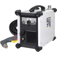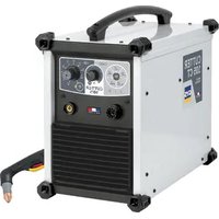
Cutter 105 CT - Slicer GYS - Free user manual and instructions
Find the device manual for free Cutter 105 CT GYS in PDF.


User questions about Cutter 105 CT GYS
0 question about this device. Answer the ones you know or ask your own.
Ask a new question about this device
Download the instructions for your Slicer in PDF format for free! Find your manual Cutter 105 CT - GYS and take your electronic device back in hand. On this page are published all the documents necessary for the use of your device. Cutter 105 CT by GYS.
USER MANUAL Cutter 105 CT GYS
natural_image
Line drawing of a portable electronic device with control panel and ventilation slots (no text or symbols)| FR | 02 / 03-13 / 81-88 |
| EN | 02 / 14-24 / 81-88 |
| DE | 02 / 25-35 / 81-88 |
| ES | 02 / 36-46 / 81-88 |
| RU | 02 / 47-58 / 81-88 |
| NL | 02 / 59-69 / 81-88 |
| IT | 02 / 70-80 / 81-88 |
CUTTER 105 CT
Découpeur plasma triphasé Three-phase plasma cutter Dreiphasiges Plasmaschneidgerät Cortador al plasma trifásico Трехфазный аппарат плазменной резки Driefasen Plasmasnijder Macchine da taglio plasma trifase Trójfazowa przecinarka plazmowa
|
text_image
Technical diagram of an industrial device with numbered components for identification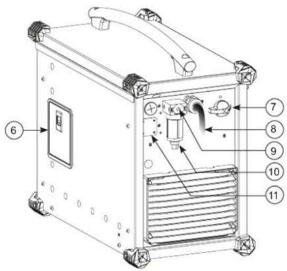
text_image
Technical diagram of a device with numbered components, likely an industrial or electronic unit, showing internal components and labeled parts.||
text_image
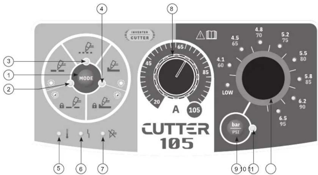
INVERTER CUTTER MODE A 105 CUTTER 105 4 8 3 1 2 5 6 7 4.5 65 4.8 70 5.2 75 4.1 60 5.5 80 5.8 85 6.2 90 6.5 95 bar PSI 9 10 11INSTRUCTIONS DE SÉCURITÉ
CONSIGNE GÉNÉRALE
INSTALLATION - FONCTIONNEMENT PRODUIT
INTERFACE HOMME-MACHINE (IHM) (II)
natural_image
Diagram of a connector with two arrows indicating direction (no text or symbols)other
| Precision Cut | Device | Value | |---|---|---| | 45 A | 039131 | 039131 | | 45 A | 039155 (x 5) | 039155 (x 5) | | 45 A | 039315 (x 5) | 039315 (x 5) | | 45 A | 039162 (x 5) | 039162 (x 5) | | 45 A | 039179 (x 5) | 039179 (x 5) | | 45 A | 039186 (x 5) | 039186 (x 5) | | 45 A | OR | OR | | 45 A | 039216 | 039216 | | 45 A | 039339 (Ohmic) | 039339 (Ohmic) | | 65 A | | | | 65 A | | | | 65 A | | | | 65 A | | | | 65 A | | | | 65 A | OR | OR | | 65 A | OR | OR | | 65 A | OR | OR | | 85 A | | | | 85 A | | | | 85 A | | | | 85 A | | | | 85 A | OR | OR | | 85 A | OR | OR | | 85 A | OR | OR | | 105 A | 039148 | 039148 | | 105 A | 039193 (x 5) | 039193 (x 5) | | 105 A | OR | OR | | 105 A | OR | OR | | 105 A | OR | OR | | 105 A | OR | OR | | 105 A | OR | OR | | 105 A | OR | OR | | 105 A | OR | OR | | 105 A | OR | OR | | 105 A | OR | OR | | 105 A | OR | OR |natural_image
Illustration of a hand holding a handheld welding torch over a flat sheet of paper (no text or symbols)natural_image
Illustration of two hands using a handheld tool to apply material to a flat surface, showing spray and motion (no text or symbols)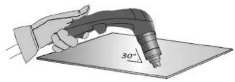
natural_image
Illustration of a hand using a power tool to apply 30-degree angle on a flat surface (no text or symbols)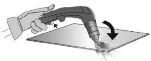
natural_image
Illustration of a hand using a handheld tool to apply material to a surface with an arrow indicating rotation (no text or symbols present)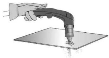
natural_image
Illustration of a hand using a handheld tool to apply material on a flat surface (no text or symbols)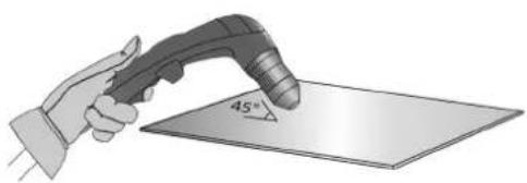
natural_image
Illustration of a hand holding a welding torch touching a 45-degree angled surface (no text or symbols present)natural_image
Illustration of a hand using a handheld tool to spray particles onto a flat surface (no text or symbols)natural_image
Illustration of a hand using a handheld tool to apply material on a flat surface (no text or symbols visible)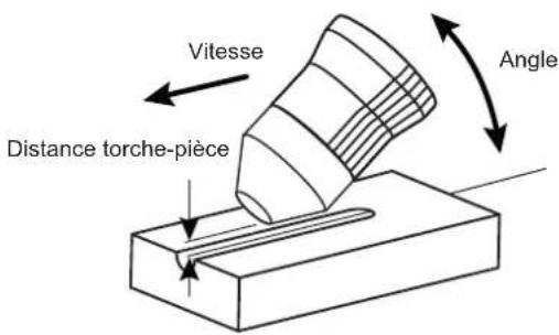
ANOMALIES, CAUSES, REMÈDES
natural_image
Technical illustration of a heat exchanger unit with internal cooling fins and a separate 3D panel assembly (no text or symbols)natural_image
Technical line drawing of a mechanical component with a highlighted circular detail (no text or symbols)These instructions must be read and fully understood before use. Do not carry out any alterations or maintenance work that is not directly specified in this manual.
The manufacturer shall not be liable for any damage to persons or property resulting from use not in accordance with the instructions in this manual. In the event of any problems or uncertainty, please consult a person qualified to deal with the unit correctly.
ENVIRONMENT
This machine must only be used for cutting operations within the limits indicated on the data plate and/or in the user manual. These safety guidelines must be observed. In the event of improper or dangerous use, the manufacturer cannot be held responsible.
The equipment must be operated and stored in a location that is free of dust, acid, flammable gases or any other corrosive substances. Operate the machine in an open, or well-ventilated area.
Temperature range:
Use between -10 and +40°C (+14 and +104°F).
Store between -20 and +55°C (-4 and 131°F).
Air humidity:
Lower than or equal to 50% at 40°C (104°F).
Lower than or equal to 90% at 20°C (68°F).
Altitude:
Up to 1,000 m above sea level (3280 feet).
PROTECTING YOURSELF AND OTHERS
Cutting can be dangerous and cause severe injuries.
Plasma cutting exposes individuals to a dangerous source of heat, arc rays, electromagnetic fields (special precautions need to be taken by people that have a pacemaker), risk of electrocution, noise and gas fumes.
To protect yourself and others, please observe the following safety instructions:

To protect yourself from burns and radiation, wear clothing that does not have turn-ups, that is insulating, dry, flame-retardant and in good condition, and that covers the whole body.

Wear protective gloves which provide electrical and thermal insulation.

Use sufficiently protective cutting gear and/or a suitable protective cap (depending on the application). Protect your eyes during cleaning procedures. Contact lenses are strictly prohibited.
It may be necessary to install fireproof welding curtains in order to protect against safety hazards such as arc rays, weld spatters and sparks.
Ensure that people around the cutting area do not look at the arc or the molten material, and are wearing appropriate protective clothes.

Use noise-cancelling headphones if the cutting process produces a noise level above the permissible limit (the same applies to anyone in the cutting area).
Keep hands, hair and clothing away from moving parts (the ventilation fan, for example).
Never remove the safety covers from the cooling unit when the machine is plugged in. The manufacturer is not liable for any injury or damage caused due to non-compliance with the safety precautions.
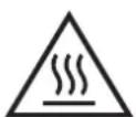
Parts that have just been cut are hot and can cause burns if handled. If the torch requires any maintenance, make sure it is sufficiently cold by waiting at least 10 minutes before carrying out any work. The cooling unit must be switched on when using a water-cooled torch to ensure that the liquid cannot cause burns.
It is important to ensure that the work area is safe before leaving it, to help protect both people and property.
The fumes, gas and dust generated by cutting are a potential health hazard. Sufficient ventilation must be provided and an additional air supply may be required. An air-fed mask could be a solution in situations where there is inadequate ventilation.
Check the extraction system performance against the relevant safety standards.
When cutting in small areas, operators must be supervised from a safe distance. Cutting certain materials containing lead, cadmium, zinc, mercury or beryllium can be particularly hazardous. It is also recommended to degrease the parts before cutting them.
Cylinders should be stored in open or well-ventilated areas. They should be stored in an upright position and kept on a stand or trolley. Do not cut in areas where grease or paint are stored.
RISK OF FIRES AND EXPLOSIONS

Protect the entire working area and ensure that flammable items are stored at a distance of at least 11 meters. Fire-fighting equipment must be present wherever cutting equipment is being used.
Beware of hot material, spatter or sparks being projected, even through cracks, as these can be a source of fire or explosion.
Keep people, flammable objects and pressurised containers at a safe distance.
Cutting in containers or pipes should be avoided and, if they are open, then flammable or explosive materials must be removed (oil, fuel, gas...).
Grinding operations should not be carried out close to the power supply or flammable materials.
ELECTRICAL SAFETY

The electrical network used must be earthed. Use the recommended fuse size from the rating plate. An electric shock, whether direct or indirect, can cause serious injury or death.
Do not touch any live part of the machine (inside or outside) when it is plugged in (Torches, cables, clamps) because they are connected to the cutting circuit.
Before opening the device, it is imperative to disconnect it from the mains and wait 2 minutes, so that all the capacitors are discharged.
Do not touch the torch and the earth clamp at the same time.
If cables or torches are damaged, they should be replaced by qualified and authorised personnel. Measure the cable cross-section according to the intended application. Always wear clothing that is dry and in good condition in order to shield yourself from the cutting circuit. Always wear insulated footwear, in all working environments.
EMC MATERIAL CLASSIFICATION

This Class A device is not intended for use in a residential location where electrical power is supplied by the public low-voltage power supply network. Ensuring electromagnetic compatibility may be difficult at these sites due to conducted, as well as radiated, radio frequency interference.
This equipment does not comply with IEC 61000-3-12 and is designed to be plugged into private, low voltage power supply networks connected to the public mains supply only at medium or high voltage level. If it is connected to a public low-voltage supply network, it is the responsibility of the installer or user of the equipment to ensure, by consulting the distribution network operator, that the equipment may be connected.
This equipment complies with IEC 61000-3-11.
ELECTRO-MAGNETIC EMISSIONS
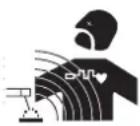
An electric current passing through any conductor produces localised electric and magnetic fields (EMF). The cutting current generates an EMF around the cutting circuit and the cutting equipment.
Electromagnetic fields (EMFs) can interfere with some medical devices; pacemakers for example. Protective measures must be taken for people with medical implants. For example, by restricting access to passers-by or conducting an individual risk evaluation for the users.
All users should follow the procedures below to minimise exposure to electromagnetic fields from the cutting circuit:
- position the cutting cables together - if possible, secure them with a clamp;
- position yourself (torso and head) as far as possible from the cutting circuit;
- never wrap the cables around your body;
- never position your body in between the cutting cables. Keep both cutting cables on the same side of your body;
- connect the return cable to the workpiece, as close as possible to the area that is to be cut;
- do not work next to, sit on, or lean against the source of cutting current;
- do not move the cutting unit when it is in use.

Pacemaker users should consult a doctor before using this equipment. Exposure to electromagnetic fields during cutting may have other, as yet unknown, health effects.
RECOMMENDATIONS FOR ASSESSING THE CUTTING AREA AND INSTALLATION
General Information
The user is responsible for the installation and use of the arc cutting equipment according to the manufacturer's instructions. If electromagnetic
disturbances are detected, the user is responsible for resolving the situation with the manufacturer's technical assistance. In certain cases, this corrective action may be as simple as earthing the cutting circuit. In other cases, it may be necessary to construct an electromagnetic shield around the cutting power source and the entire room, by fitting input filters. In any case, electromagnetic interference should be reduced until it is no longer a cause for concern.
Assessment of the cutting area
Before installing arc cutting equipment, the user must assess the potential electromagnetic problems in the surrounding area. The following should be taken into account:
a) the presence of power, control, signalling and telephone cables above, below and adjacent to the arc cutting equipment;
b) radio and television receivers and transmitters;
c) computers and other control equipment;
d) safety-critical equipment, e.g. industrial machinery protection;
e) the health of nearby persons, e.g. those using pacemakers or hearing aids;
f) equipment used for calibrating or measurement;
g) the sensitivity of other equipment in the surrounding area.
The user must ensure that other equipment installed in the vicinity is compatible. This may require further protective measures;
h) the time of day when the cutting or other operations are to be carried out.
The size of the surrounding area to be taken into account depends on the structure of the building and other activities taking place there. The surrounding area may extend beyond the boundaries of the facility.
Assessment of the cutting equipment
In addition to assessing the surrounding area, the assessment of arc cutting installations can be used to identify and resolve cases of interference. It is appropriate that the assessment of any emissions should include in situ procedures as specified in Article 10 of CISPR 11. In-situ measurements can also be used to verify the effectiveness of any mitigation measures.
RECOMMENDATIONS ON METHODS FOR REDUCING ELECTROMAGNETIC EMISSIONS
a. The mains supply network: Plasma cutting equipment should be connected to the public power supply network in accordance with the manufacturer's recommendations. If any interference occurs, it may be necessary to take additional precautionary measures such as filtering the mains power supply. Consideration should be given to shielding the power cable in a metal conduit or equivalent for permanently installed arc cutting equipment. The power cable should be protected along its entire length. The shielding should be connected to the cutting current power source to ensure good electrical contact between the conduit and the enclosure of the cutting current power source.
b. Maintenance of arc cutting equipment: Arc cutting equipment should undergo routine maintenance in accordance with the manufacturer's recommendations. All accesses, service doors and covers should be closed and properly secured when arc cutting equipment is in use. The arc cutting equipment must not be modified in any way, except for the changes and adjustments outlined in the manufacturer's instructions. It is particularly important that the spark gap of the arc ignition and stabilisation circuit is adjusted and maintained in accordance with the manufacturer's recommendations.
c. Cutting cables: Cables should be as short as possible, placed close together, either near or on the ground.
d. Equipotential bonding: Consideration should be given to linking all metal objects in the surrounding area. However, metal objects connected to the workpiece increase the risk of electric shock if the operator touches both the metal parts and the electrode. It is necessary to insulate the operator from such metal objects.
e. Earthing the workpiece before cutting: In cases where the workpiece that is to be cut is unearthed for electrical safety reasons, or because of its size and location (such as the hulls of ships or the structural steelwork in buildings), an earthed connection can, in some cases but not always, reduce emissions. Care must be taken to avoid the earthing of any parts that could increase the risk of injury to the user, or cause damage to other electrical equipment. If necessary, the connection between the item to be cut and earth should be made directly, but in some countries where this type of direct connection is not permitted, the connection should be made with an appropriate capacitor chosen in accordance with the relevant national regulations.
f. Protection and shielding: Selective protection and shielding of other cables and equipment in the surrounding area can help minimise interference problems. Protection of the entire cutting area may be required for certain specialist applications.
TRANSPORT AND TRANSIT OF THE CUTTING POWER SOURCE

The machine is equipped with a handle for easy transportation. Be careful not to underestimate the weight of the unit. The handle cannot be used to hang or attach the machine on something else.
Do not use the cable or torch to move the machine. It should be moved in an upright position.
Do not carry the power source over the heads of people or objects.
SETTING UP THE EQUIPMENT
- Put the machine on the floor (maximum incline of 10^ )
- Provide an adequate area to ventilate the machine and access the controls.
- Do not use in an environment containing electrically conductive metallic dust.
- The machine must be placed in a sheltered area away from rain or direct sunlight.
- The equipment has an IP23 protection rating which means:
- Protection against access to dangerous parts from solid bodies of a ≥12.5mm diameter and,
- Protection against rain inclined at 60% towards the vertical.
The equipment can be used outside in accordance with the IP23 protection certification.
Power cables, extension leads, and welding cables must be fully uncoiled to prevent overheating.

The manufacturer assumes no responsibility for damage to persons or objects caused by improper and dangerous use of this equipment.
MAINTENANCE / RECOMMENDATIONS


- Maintenance should only be carried out by a qualified person. Annual maintenance is recommended. Ensure the machine is unplugged from the mains, and then wait 2 minutes before carrying out maintenance work. Inside the machine, the voltages and currents are high and dangerous.
- Regularly remove the cover and blow out any dust. Take the opportunity to have the electrical connections checked by qualified personnel using an insulated tool.
- Regularly check the condition of the power cable. If the power cable is damaged, it must be replaced by the after-sales department of the manufacturer, or a similarly qualified person, in order to avoid any potential danger.
- Ensure the vents of the device are not blocked to allow adequate air circulation.
- Do not use this power source to thaw pipes, recharge batteries, or start engines.
- Check that the torch does not have any cracks or exposed wires.
- Check that the consumables are installed properly and not worn.
INSTALLATION - USING THE PRODUCT
Only experienced personnel, authorised by the manufacturer, may carry out the set-up of the machine. During set-up, make sure that the product is disconnected from the mains. We recommend that you use the cutting torch and cables supplied with the unit in order to achieve the optimum settings for the product.
EQUIPMENT SUPPLIED WITH
| CUTTER 105 CT081093 081109 | ||
 | - | √ |
 4 r 4 r  | √ | √ |
s  | - | √ |
 Pneumatic fittings Pneumatic fittings | √8 mm + 10 mm 8 mm + 10 mm | √ |
The accessories supplied with the product must only be used with this particular unit.
DESCRIPTION
The CUTTER 105 CT is a three-phase plasma cutting and gouging power source.
It allows:
- cutting of all metals
- gouging on all metals
Both processes require the use of appropriate consumables and compressed air or nitrogen.
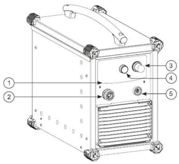
DESCRIPTION OF THE EQUIPMENT (I)
1- Human-machine interface 7- On/off switch
2- Plasma torch connector 8- Power cable (5 m)
3- Pressure adjustment knob. 9- Location for pneumatic connection
4- Current setting potentiometer. 10- Filter
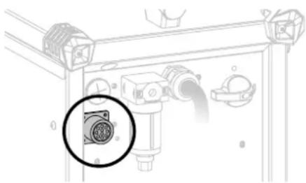
5- Earth clamp connection socket 11-CNC-1 kit installation hatch (optional, ref. 039988)
6- Accessory box hatch
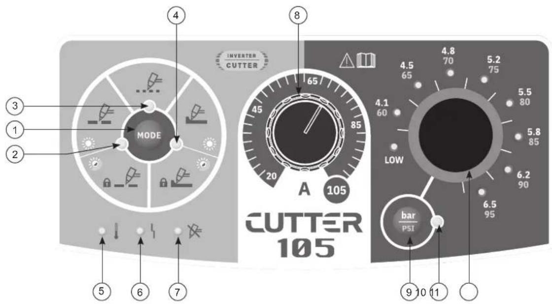
HUMAN-MACHINE INTERFACE (HMI) (II)
1- Mode selector button
2- Full sheet cutting indicator
3- Perforated sheet cutting indicator
4- Gouging indicator
5- Thermal protection indicator
6- Error during normal operation indicator
7- «Stop caused by action on the torch» indicator
8- Current setting potentiometer.
9- Test and air pressure adjustment button
10- Air test in progress indicator
11- Air pressure adjustment knob and pressure chart
POWER SUPPLY / POWER UP
- This equipment is supplied with a 32 A EN 60309-1 socket and should only be used on a three phase, 400 V (50-60 Hz), four wire, earthed electrical system.
- The effective absorbed current (11eff) for maximum operating conditions is indicated on the equipment. Check that the power supply and its protection (fuse and/or circuit breaker) are compatible with the current required to run the machine. In some countries, it may be necessary to change the plug in order to use it at maximum capacity.
- The unit is designed to operate on 400V + / - 15% . It will switch into a protection state if the supply voltage is less than 340Veff or greater than 460Veff (a fault code will appear on the keypad display).
To switch the unit on, turn the on/off switch (I-7) to position I, and to switch it off, turn it to position O.
Warning! Never switch off the power supply when the unit is under load.
CONNECTION TO POWER GENERATOR
The product can be powered by a generator provided that the auxiliary power supplied meets the following requirements:
- The output voltage must be alternating, with an RMS value of 400V +/- 15%, and a peak voltage of less than 700V,
- The frequency must be between 50 and 60 Hz.
It is essential to check these conditions, as many generators produce high-voltage spikes that can damage your equipment.
USING EXTENSION LEADS
All extension leads must be of a size and cross-section appropriate for the voltage of the appliance.
Use an extension lead that complies with national safety regulations.
| Input voltage Extension lead cross section (<45m) | |
| 400 V 4mm ^2 | |
AIR SUPPLY
The air supply can come from a compressor or high-pressure bottles. A high-pressure manometer must be used on any type of air supply, and must be able to deliver gas to the air inlet of the plasma cutter. This machine is fitted with a built-in air filter (5μm), but additional filtration may be required depending on the quality of the air used (optional contaminant filter, ref. 039728).
If the air quality is poor, the cutting speed will be reduced, the quality of the cut will decline, the cutting thickness capacity will be affected, and the service life of the consumables will be diminished.
For best performance, the compressed air must comply with the standard ISO8573-1, class 1.2.2. The maximum vapor pressure point must be -40 °C. The maximum quantity of oil (aerosol, liquid and vapour) must be 0.1 mg/m3.
natural_image
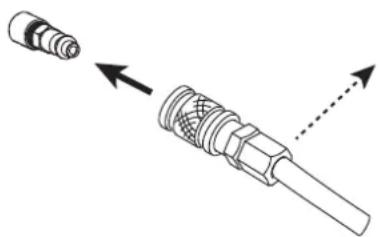
Diagram of a connector with two arrows indicating direction (no text or symbols)Connect the compressed air supply to the power source using an inert gas hose with an internal diameter of 9.5 mm and a quick-fit coupling.
The pressure must not exceed 9 bar, otherwise the filter tank could rupture.
The recommended input pressure during air circulation is 5 to 9 bars with a minimum debit of 305 L/min.
CHOICE OF CONSUMABLES
- Manual cutting with MT-125 torch (6 m: Ref. 039506, 12 m: Ref. 039513):
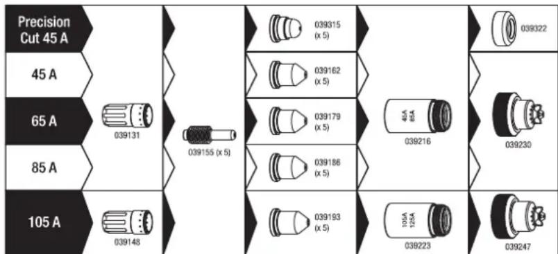
text_image
Precision Cut 45 A 45 A 65 A 85 A 105 A 039131 039155 (x 5) 039315 (x 5) 039162 (x 5) 039179 (x 5) 039186 (x 5) 039216 4A 6A 039230 039148 039193 (x 5) 10A 12A 039223 039247• Automatic cutting with AT-125 torch (6 m: Ref. 038479, 12 m: Ref. 039520, 15 m: Ref. 069787, 20 m: Ref. 069794):
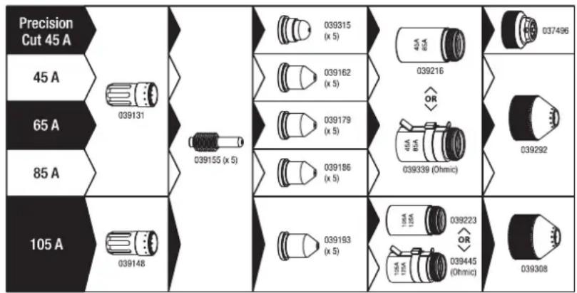
text_image
Precision Cut 45 A 45 A 65 A 85 A 105 A 039131 039155 (x 5) 039315 (x 5) 039162 (x 5) 039179 (x 5) 039186 (x 5) 039193 (x 5) 039216 OR 48A 88A 039339 (Ohmic) 037496 039292 039308 039223 OR 18A 12A 15A 12A 039445 (Ohmic)• Gouging with MT-125 torch (6 m: Ref. 039506, 12 m: Ref. 039513):

text_image
65-85 A 039131 039261 039216 105 A 039148 039155 (x 5) 039278 ( x 5 ) 106A 125A 039223 039254CUTTING CURRENT SETTINGS

In order to achieve the expected performance and prolong the service life of the consumables, be sure to set the current in accordance with the value indicated on the consumable (e.g. 45 A = 45 amperes)..
This is adjusted by simply turning the current adjustment potentiometer.
AIR PRESSURE ADJUSTMENT
To reach optimum performance and extend the service life of the consumables, it is very important to set the air pressure correctly.
It is recommended to check/adjust the pressure in the event of:
- change of air connection point or air system
- change of torch length
- change of consumable type
- if you are experiencing any problems

Press the PSI button, the air will continuously discharge from the torch, the LEDs on the Bar-graph will light up and indicate the pressure reading at the torch inlet.
Unlock the pressure adjustment knob by pulling it towards you, then turn it to adjust the pressure required to suit the application. Once the pressure has been set correctly, lock the knob by pressing it.
Pressure depends on:
- the length of the torch (a longer torch requires higher pressure to compensate for the difference in pressure arising from the increase in length)
- the type of job, cutting or gouging (gouging consumables require lower pressure).
- refer to the instructions in the torch manual or the markings on the product to set the optimum pressure.
Recommended pressure:

Cutting Gouging
6 m 5.2 bar / 75 Psi 4.5 bar / 65 Psi
12 m 5.5 bar / 80 Psi 4.8 bar / 70 Psi
20 m 5.8 bar / 85 psi 5.2 bar / 75 psi
CHOICE OF CUTTING MODE:
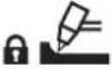
The cutting mode is selected by pressing the selection button
MODE
| Icon LED status Description | ||
 |  | Cutting / cutting with trigger lockUse one of these two modes to execute the cut on solid sheet material. |
| [85ZS] | [BK48]fl: g | Pressing the trigger creates the arc, which is stopped either by releasing the trigger or by «unblocking» (the arc stops by itself).For longer cuts, it is possible to use the locking-trigger mode, meaning that the trigger can be released for the duration of the cut. This reduces fatigue and also means you can keep your hand a little further away from the cutting area. |
 | Cutting perforated sheet metalUse this mode to carry out cutting tasks on perforated sheet material, without extinguishing the arc between the two sections of the workpiece.The arc remains continuously engaged, so the cut proceeds as if it were a solid sheet. Because of the way it works, this mode tends to cause more wear and tear on the nozzle. This mode should therefore only be used for perforated materials. | |
 |  | Gouging / gouging with trigger lockUse one of these two modes for gouging applications. |
 |  fl: g fl: g | Pressing the trigger creates the arc, which is stopped either by releasing the trigger or by «unblocking» (the arc stops by itself).For longer cuts, it is possible to use the locking-trigger mode, meaning that the trigger can be released for the duration of the cut. This reduces fatigue and also means you can keep your hand a little further away from the cutting area. |
CUTTING SEQUENCE
1- When the trigger is pressed, an arc is generated: the pilot arc. This is a low-power arc established between the electrode and the nozzle, allowing ignition on the metal workpiece that is to be cut.
2- When the pilot arc touches the workpiece, the plasma cutter activates. The arc then flows between the electrode and the workpiece, and the power source increases the current to the value set by the user.
3- At the end of the cut (trigger release or unblocking), the arc stops, but air continues to flow out of the torch for some time in order to cool the torch and the consumables.
MANUAL CUTTING FROM THE EDGE OF THE WORKPIECE:
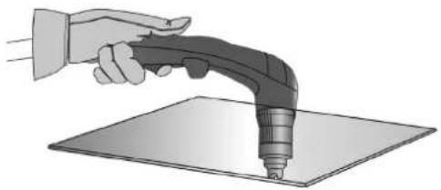
① With the ground clamp attached to the workpiece, hold the base of the torch perpendicular (90°) to the end of the workpiece.
② Pull the trigger on the torch to initiate the arc until it has fully penetrated the workpiece.
natural_image
Illustration of a hand holding a handheld electric shaver with a pointed tip, placed on a flat surface (no text or symbols)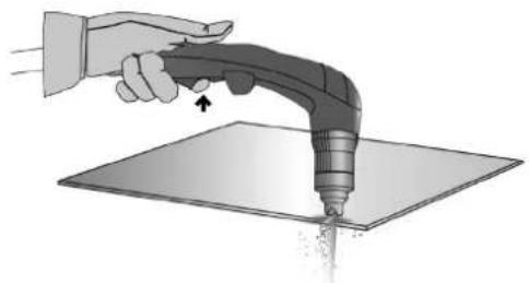
natural_image
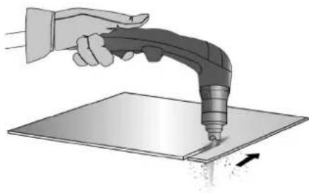
Illustration of a hand using a handheld tool to apply material on a flat surface (no text or symbols)③ Once the cut has begun, lightly drag the tip over the workpiece to continue cutting. Try to maintain a steady pace.
natural_image
Illustration of a hand using a handheld tool to apply material on a flat surface, with motion arrows indicating movement (no text or symbols)STARTING THE CUT ON THE FACE OF THE WORKPIECE:
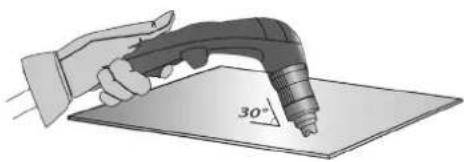
① With the ground clamp attached to the workpiece, hold the torch at an angle of approximately 30^ to the workpiece.
natural_image
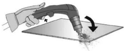
Illustration of a hand using a power tool to draw a 30-degree angle on a flat surface (no text or symbols)② Pull the trigger on the torch to initiate the arc while maintaining the angle (30°) to the workpiece. Slowly rotate the torch to a perpendicular position (90°).
natural_image
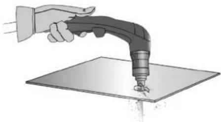
Illustration of a hand using a handheld tool to apply material on a flat surface, with an arrow indicating the process (no text or symbols present)Hold the torch steady while continuing to hold down the trigger. If the sparks project from the bottom of the workpiece, the arc has pierced the material.
natural_image
Illustration of a hand using a handheld tool to lift a surface, with no text or symbols present.④ Once the cut has begun, lightly drag the tip over the workpiece to continue cutting. Try to maintain a steady pace.
GOUGING:
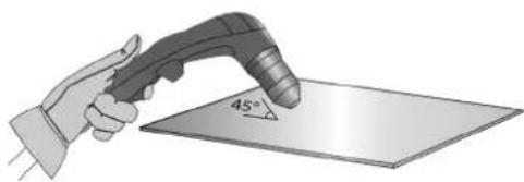
With the ground clamp attached to the workpiece, hold the torch at an angle of about 45^ to the surface of the material, keeping the gouging tip about 2 mm away from the workpiece before triggering the torch.
text_image
45°② Pull the trigger on the torch to initiate the arc, keeping the angle at 45^ to the workpiece as you work into the groove.
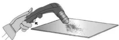
natural_image
Illustration of a hand using a handheld tool to apply powder onto a flat surface (no text or symbols)③ Push the plasma arc in the direction of the gouge you intend to produce. Maintain a minimum distance between the torch tip and the molten material to avoid premature wear of the consumables or damage to the torch.
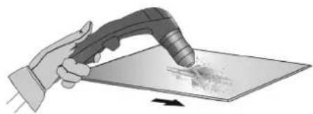
natural_image
Illustration of a hand using a handheld tool to spread material on a flat surface (no text or symbols)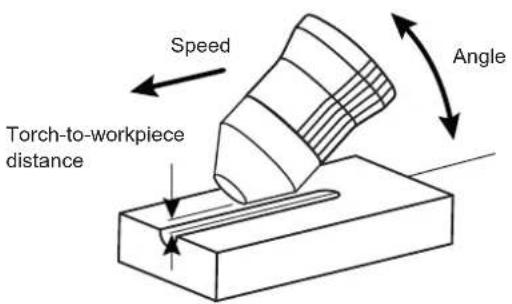
text_image
Speed Torch-to-workpiece distance AngleGROOVE SHAPE
You can vary the profile of the groove by altering the movement speed of the torch on the workpiece, the distance between the torch and the workpiece, the angle of the torch on the workpiece, and the output current from the power source.
CHANGING THE SHAPE OF THE GROOVE
| DESIRED | Width | ||||||||
| Depth | |||||||||
| Solutions | Increase the speed | Reduce the speed | Increase the torch-to-work-piece distance | Reduce torch-to-work-piece distance | Increase the angle | Reduce the angle | Increase the current | Decrease the current | |
PROTECTIONS
| Torch interventionThe operator will be required to do maintenance on the torch and its accessories (changing consumables, disconnecting the torch).If the plasma cutter is switched on in this scenario, the «stop caused by action on the torch» indicator (II-7) will light up to indicate that the power source has detected that an action is being performed on the torch and that it is safe to do so.When the torch and / or consumables are reassembled, the message disappears and the cutter will be operational again.If the product is functional (cutting) but this problem persists, make sure to have the product checked by the aftersales team. | |
| ● LOW | Insufficient air pressureThe «Insufficient pressure» indicator lights up if the pressure is too low for the machine to work properly, or if the air is not connected to the cutter.Reconnect the air supply to the compressed air connector (I-9) on the rear of the product. If the indication persists, press the «air pressure test and adjustment» button (II-9) and turn the pressure adjustment knob (II-11) until you obtain the correct air pressure for the application in question (see paragraph «Adjusting the air pressure»). |
| ● ! | Thermal protectionShould the unit overheat (due to non-compliance with operating conditions or prolonged use at ambient temperatures in excess of 40°), the Plasma cutter will suspend output in order to cool down.The thermal protection indicator (II-5) lights up to signal that operation has been interrupted due to overheating. The indicator goes off and the machine is ready to use again. |
| ● ↓ | Disruption of normal operation |
TROUBLESHOOTING
| Error notification SYMPTOMS POSSIBLE CAUSES SOLUTIONS | |||
| Torch intervention | Torch disconnected Check and reconnect the torch. | ||
| Dismantled consumables | Check that all consumables are present and that the nozzle is tight. | ||
 (flashing) (flashing) | Consumable problem | The electrode is not in contact with the nozzle | Check that the consumables are present and in good condition, replace them if necessary and try again. |
| The electrode can not retract | Check that the electrode is not fused to the nozzle, verify that the electrode is freely movable, change the consumables if necessary. | ||
 | Air pressure too low | The air hose is not connected or the pressure is set too low | Check the air hose connection, switch on the compressor, and check the pressure on the inlet side of the plasma cutter. |
 | Thermal protection | Intensive use (failure to comply with specified duty cycles) | Leave the unit switched on while it cools down and wait for the thermal fault LED to go out. |
| Ventilation is obstructed, or the product is located in a confined area. | Improve the ventilation in the area, or change the location of the unit. | ||
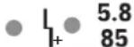 | Overvoltage | The voltage is too high and could damage the product | Have the installation checked by an electrician. |
 | Under voltage | The voltage is too low to guarantee a satisfactory performance | |
 | Phase missing One phase is missing | ||
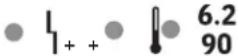
 | Fan issue | The fan is not turning | Check that there is no debris preventing the fan from rotating normally. |
| The fan is not running at the right speed. | Check connection, replace fan if necessary. | ||
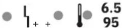
 | Incorrect temperature information | The temperature sensor is damaged or disconnected | Check sensor connections, replace them if necessary |
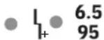 | Current has not been generated | No contact between electrode and nozzle | Check that consumables are present and in good condition. Change them if necessary. Restart the machine and try again. |
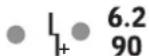 | Power relay fault. The power relay does not close Return the product for repair. | ||
 | No arc | The electrode has not retracted or there is not enough air coming out. | Check that the electrode is properly retracting.Check the pneumatic system (hose diameter too small and/or hose too long, pinched hose).Ensure that the compressor specifications are suitable. |
| - | Arc stops after 3 seconds of cutting | No current detection in the earth clamp | Check that the earth clamp is properly connected to the workpiece and on a clean surface (no rust, paint or grease). |
| - | The machine does not switch on. | No power supply | Check that the power cable is plugged into the socket and that the on/off switch is in the on position. |
| Check that the circuit-breaker has not tripped. | |||
| - | The pilot-arc cuts out too quickly | Worn consumables | Check the condition of the consumables and replace them if necessary. |
| - | The arc stops mid-way through a cut | Cutting speed too slow on thin sheet metal | Reduce the current / increase the movement speed. |
| Poor quality ground clamp contact | Check that the earth clamp is properly connected to the workpiece and on a clean surface (no rust, paint or grease). | ||
| Cutting height too high | Use a cutting guide and keep it in contact with the workpiece. | ||
| - | Premature wear of consumables | Cutting current not suitable for the consumables in use | Refer to «Setting the cutting current» section. |
| Inappropriate air pressure | Refer to «Setting the air pressure» section. | ||
| Air humidity | Purge the air filters in the compressed air system. Install the additional filter-dryer, ref. 039728. |
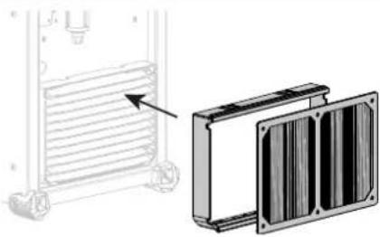
OPTIONAL FILTER KIT
natural_image
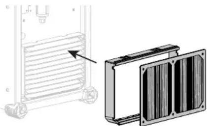
Technical illustration of a heat exchanger unit with side-mounted cooling fins and a separate 3D panel assembly (no text or symbols)Dust filter (ref. 046580) with filtration to: 630 μm (0.63 mm).
Please note that the use of this filter reduces the duty cycle of your machine.
To avoid the risk of overheating due to clogged air vents, the dust filter should be cleaned on a regular basis. Unclip and clean with compressed air.
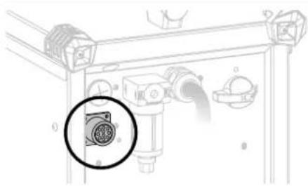
OPTIONAL ANALOGUE KIT
natural_image
Technical diagram of a mechanical piping system with a highlighted component (no text or symbols)The analogue CNC-1 kit (ref. 039988) enables simple information to be exchanged between the plasma cutter and the numerical control of a cutting table, to ensure correct operation.
WARRANTY CONDITIONS
The warranty covers any defects or manufacturing faults for two years from the date of purchase (parts and labour).
The warranty does not cover:
- Any other damage caused during transport.
• The general wear and tear of parts (i.e. : cables, clamps, etc.). - Incidents caused by misuse (incorrect power supply, dropping or dismantling).
- Environment-related faults (such as pollution, rust and dust).
In the event of a breakdown, please return the item to your distributor, along with:
- a dated proof of purchase (receipt or invoice etc.).
- a note explaining the malfunction.
SICHERHEITSHINWEISE
ALLGEMEINER HINWEIS
natural_image
Diagram of a connector with two arrows indicating direction (no text or symbols)natural_image
Illustration of a hand holding a handheld welding torch over a flat sheet of paper (no text or symbols)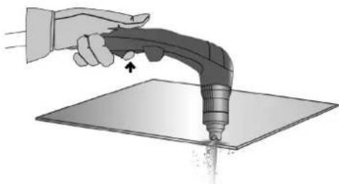
natural_image
Illustration of a hand using a handheld tool to spray or brush on a flat surface (no text or symbols)natural_image
Illustration of a hand using a handheld tool to press or spread material on a flat surface, with an arrow indicating motion (no text or symbols present)natural_image
Illustration of a hand using a power tool to apply 30-degree angle on a flat surface (no text or symbols)natural_image
Illustration of a hand using a handheld tool to apply material or spray onto a flat surface, with an arrow indicating the process (no text or symbols present)natural_image
Illustration of a hand using a handheld tool to lift a surface, with no visible text or symbols.natural_image
Illustration of a hand holding a welding torch touching a 45-degree angle on a flat surface (no text or symbols)natural_image
Illustration of a hand using a handheld tool to apply particles onto a flat surface (no text or symbols)
natural_image
Illustration of a hand using a handheld tool to apply material on a flat surface (no text or symbols visible)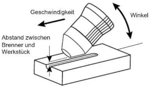
natural_image
Technical illustration of a heat exchanger unit with side-mounted cooling fins and a separate 3D panel assembly (no text or symbols)natural_image
Technical diagram of a mechanical assembly with a highlighted circular component (no text or symbols)natural_image
Diagram of a connector with two arrows indicating direction (no text or symbols)natural_image
Illustration of a hand holding a handheld electric shock absorber on a flat surface (no text or symbols)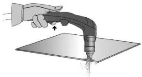
natural_image
Illustration of a hand using a handheld tool to apply material on a flat surface (no text or symbols)natural_image
Illustration of a hand using a handheld tool to press or spread material on a flat surface, with an arrow indicating motion (no text or symbols present)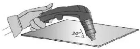
natural_image
Illustration of a hand using a power tool to cut a 30-degree angle on a flat surface (no text or symbols)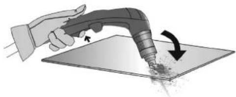
natural_image
Illustration of a hand using a handheld tool to apply material on a flat surface, with an arrow indicating the process (no text or symbols present)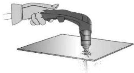
natural_image
Illustration of a hand using a handheld tool to lift a surface, with no text or symbols present.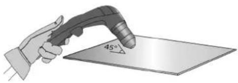
natural_image
Illustration of a hand holding a welding torch touching a 45-degree angle on a flat surface (no text or symbols)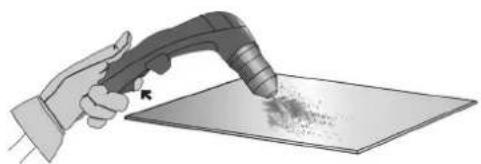
natural_image
Illustration of a hand using a handheld tool to apply material onto a flat surface (no text or symbols)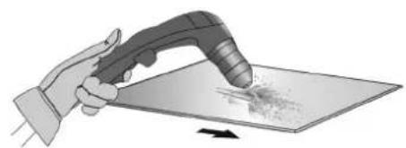
natural_image
Illustration of a hand holding a tool interacting with a surface, showing a textured surface (no text or symbols)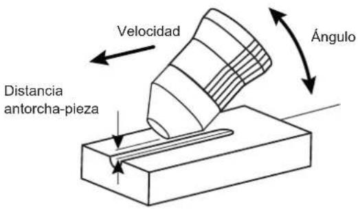
natural_image
Technical illustration of a heat exchanger unit with side-mounted cooling fins and a separate 3D panel showing internal structure (no text or symbols)natural_image
Technical line drawing of a pipe fitting with a magnified inset showing a connector detail (no text or symbols)text_image
Technical diagram of a device with numbered components and labeled parts, likely for assembly or maintenance instructions.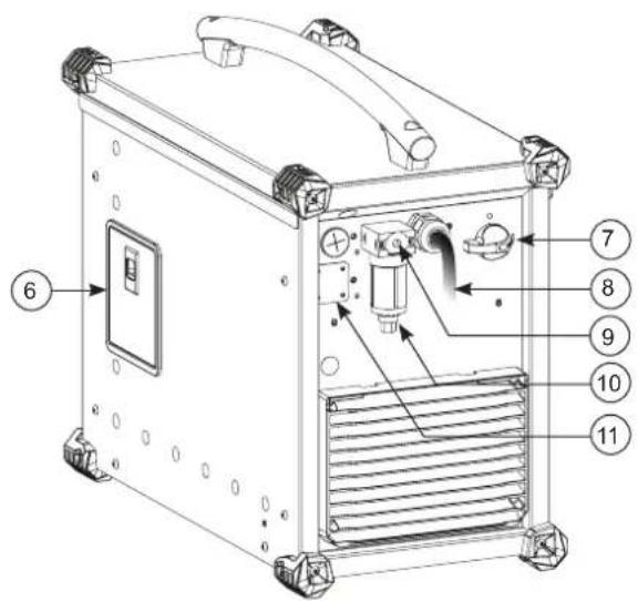
text_image
Technical diagram of a device with numbered components, likely an industrial or electronic unit, showing internal components and labeled parts.||
text_image
INVERTER CUTTER MODE A 105 CUTTER 105 4 8 3 1 2 5 6 7 4.5 65 4.8 70 5.2 75 4.1 60 5.5 80 5.8 85 6.2 90 6.5 95 bar /PSI 9 10 11natural_image
Diagram showing two types of connectors with arrows indicating direction (no text or symbols)natural_image
Illustration of a hand using a handheld electric welding torch to lift a metal sheet (no text or symbols)natural_image
Illustration of two hands using a handheld tool to lift or spread material on a flat surface, with arrows indicating motion (no text or symbols)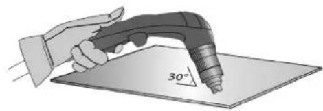
natural_image
Illustration of a hand using a power tool to draw a 30-degree angle on a flat surface (no text or symbols present)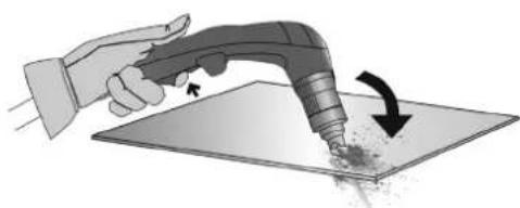
natural_image
Illustration of a hand using a handheld tool to apply material on a flat surface, with an arrow indicating the process (no text or symbols present)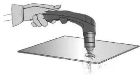
natural_image
Illustration of a hand using a handheld tool to lift a surface, with no visible text or symbols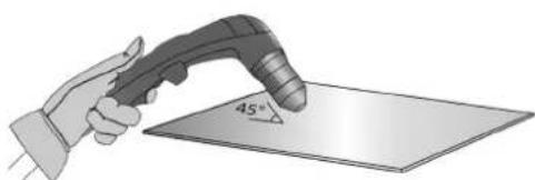
natural_image
Illustration of a hand holding a welding torch touching a 45-degree angled metal surface (no text or symbols present)natural_image
Illustration of a hand using a handheld electric shaver to apply particles on a flat surface (no text or symbols)natural_image
Illustration of a hand using a handheld tool to apply material on a flat surface (no text or symbols visible)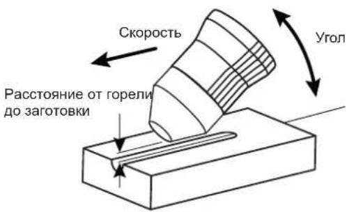
natural_image
Technical illustration of a heat exchanger unit with side-mounted cooling fins and a separate 3D panel assembly (no text or symbols)natural_image
Technical line drawing of a mechanical assembly with a highlighted circular component (no text or symbols)INSTALLATIE - WERKING VAN HET APPARAAT
natural_image
Diagram showing two types of connectors: a cylindrical connector and a threaded connector, with arrows indicating direction (no text or symbols)natural_image
Illustration of a hand using a handheld electric welding torch to apply material on a flat surface (no text or symbols)natural_image
Illustration of two hands using a handheld tool to apply material to a flat surface, showing motion and force direction (no text or symbols)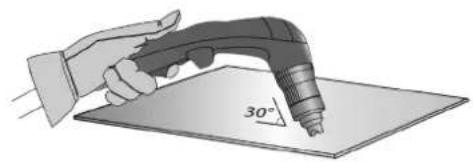
natural_image
Illustration of a hand using a power tool to draw a 30-degree angle on a flat surface (no text or symbols)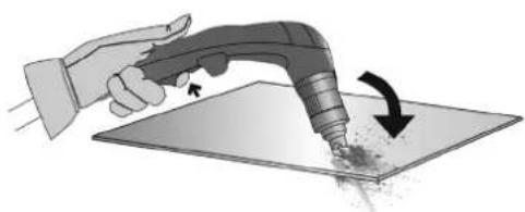
natural_image
Illustration of a hand using a handheld tool to apply material or spray onto a flat surface, with an arrow indicating the process (no text or symbols present)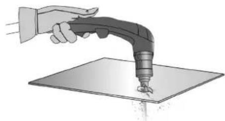
natural_image
Illustration of a robotic arm gripping a tool over a flat surface (no text or symbols)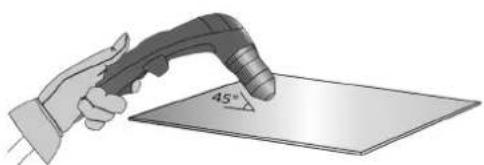
natural_image
Illustration of a hand holding a welding torch touching a 45-degree angle on a flat surface (no text or symbols)natural_image
Illustration of a hand using a handheld tool to apply particles onto a surface (no text or symbols)natural_image
Illustration of a hand using a handheld tool to spread material on a flat surface (no text or symbols)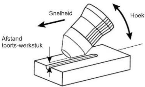
KIT FILTER OPTIONEEL
natural_image
Technical illustration of a heat exchanger unit with cooling fins and a side panel (no text or symbols)ANALOGE KIT OPTIONEEL
natural_image
Technical line drawing of a mechanical component with a circular inset showing a connector detail (no text or symbols)natural_image
Diagram showing two types of connectors: a small cylindrical component and a larger threaded connector with internal mesh structure (no text or symbols)natural_image
Illustration of a hand using a handheld electric welding torch to apply material on a flat surface (no text or symbols)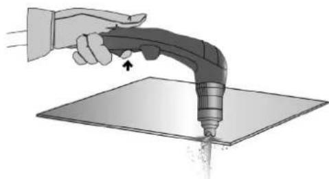
natural_image
Illustration of a hand using a handheld tool to apply material on a flat surface (no text or symbols)natural_image
Illustration of a hand using a handheld tool to press or spread material on a flat surface, with an arrow indicating motion (no text or symbols present)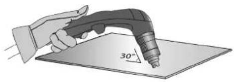
natural_image
Illustration of a hand using a power tool to draw a 30-degree angle on a flat surface (no text or symbols)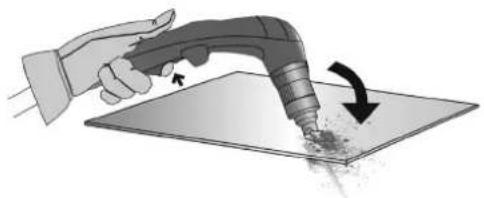
natural_image
Illustration of a hand using a handheld tool to apply material on a flat surface, with an arrow indicating rotation (no text or symbols present)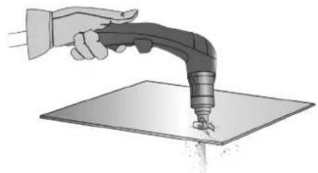
natural_image
Illustration of a hand using a handheld tool to lift a surface, with no text or symbols present.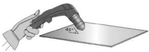
natural_image
Illustration of a hand holding a welding torch touching a 45-degree angle on a flat surface (no text or symbols)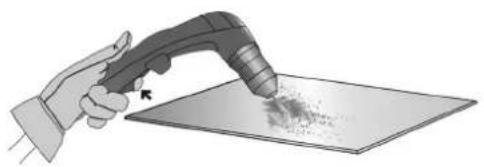
natural_image
Illustration of a hand using a handheld tool to scrape or spread material on a flat surface (no text or symbols)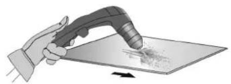
natural_image
Illustration of a hand using a handheld tool to cut or spread material on a flat surface (no text or symbols)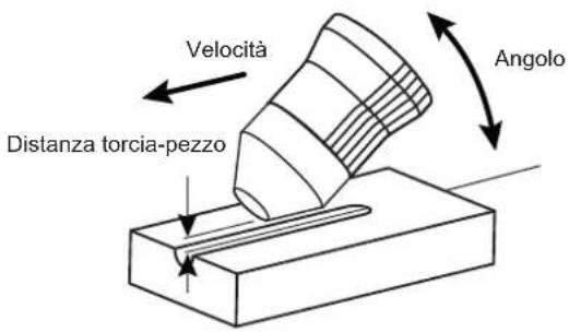
natural_image
Technical illustration of a heat exchanger unit with side-mounted cooling fins and a separate 3D panel showing internal structure (no text or symbols)natural_image
Technical line drawing of a piping assembly with a highlighted circular component (no text or symbols)text_image
Exploded view diagram of an electronic device with numbered components and exploded views| 1 Poignée / Handle 56044 | |
| 2 Patin 3 points / Feet 3 points 56120 | |
| 3 Filtre / Filter 55389 | |
| 4 Circuit de mise à jour / Update circuit 97794C | |
| 5 Interrupteur triphasé / Three-phase switch 51061 | |
| 6 Grille extérieure / External grid 56094 | |
| 7 Grille intérieure / Inner grid 56095 | |
| 8 Circuit secondaire / Secondary circuit E0224C | |
| 9 Résistance ISOTOP / ISOTOP resistance | 52270 |
| 10 Diode ISOTOP / ISOTOP diode | 52206 |
| 11 Module IGBT / IGBT module | 52204 |
| 12 Circuit CEM / EMC circuit | E0225C |
| 13 Electrovanne / Solenoid valve | 42222 |
| 14 Inductance de sortie / Output inductance 96196 | |
| 15 Transformateur / Transformer 63579 | |
| 16 Clavier / Keyboard 51893 | |
| 17 Régulateur de pression / Pressure regulator 71359 | |
| 18 Connecteur de pince de masse / Ground clamp connector 51469 | |
| 19 Connecteur de torche / Torch connector F1143 | |
| 20 Circuit alimentation / Power supply circuit 97075C | |
| 21 Circuit de contrôle / Control circuit E0251C | |
| 22 Circuit principal / Main circuit E0228C | |
| 23 Circuit potentiomètre / Potentiometer circuit E0256C | |
| 24 Circuit primaire / Primary circuit E0226C | |
| 25 Module IGBT / IGBT module 52204 | |
| 26 Ventilateur / Fan | 51290 |
| 27 Cordon secteur / Power cord | 5 m 21589 |
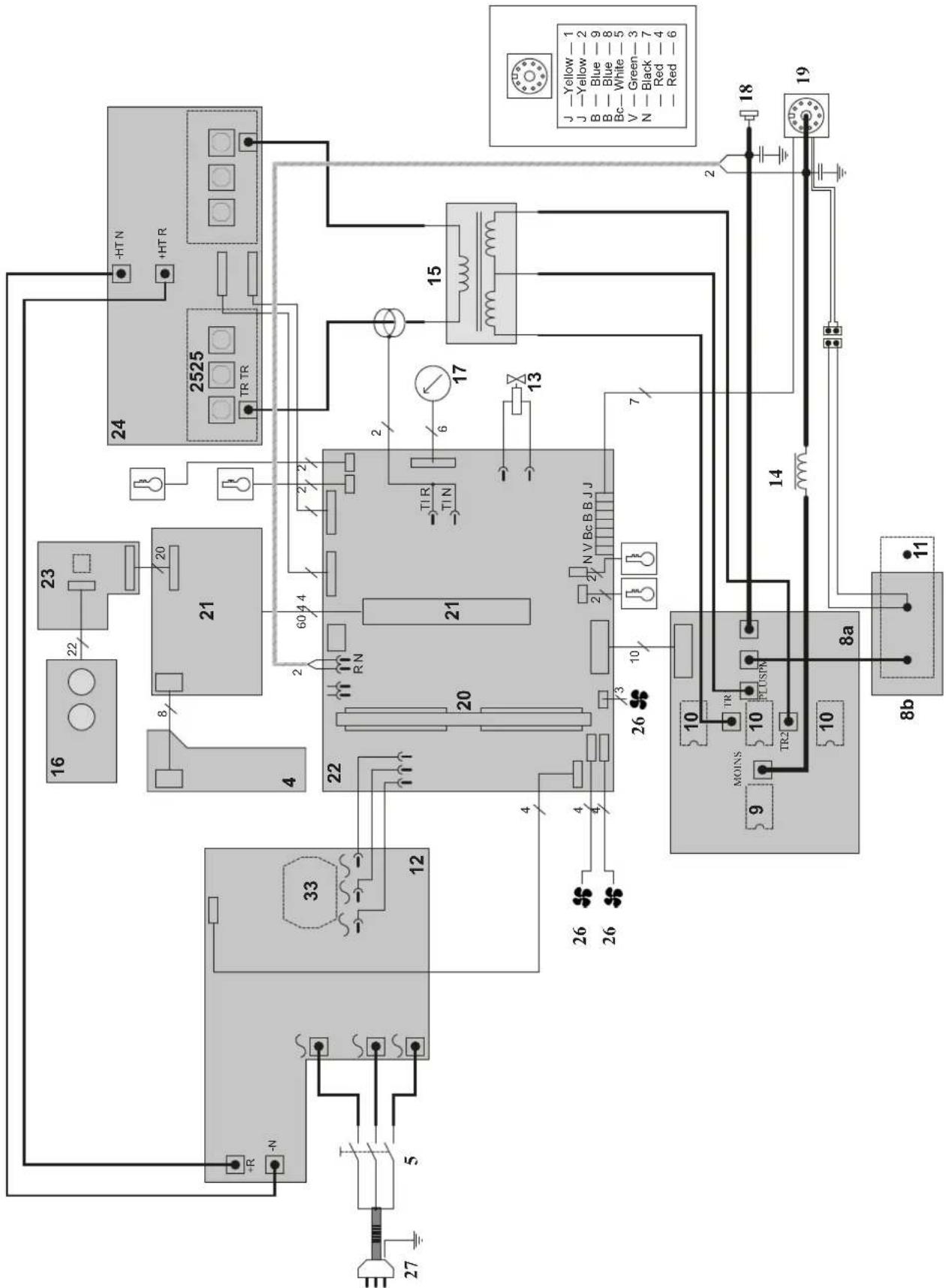
CIRCUIT DIAGRAM / SCHALTPLAN / DIAGRAMA ELECTRICO / ЭЛЕКТРИЧЕСКАЯ СХЕМА / ELEKTRISCHE SCHEMA / SCEMA ELETTRICO
105 CT
text_image
HTN +HTR 2525 TR TR 15 JYellow-1 J-Yellow-2 B-Blue-9 B-Blue-8 Bc-White-5 V-Green-3 N-Black-7 Red-4 Red-6 18 19 2 24 2525 17 13 20 60 4 2 TIR TIN N.V.Bc.BBJJ 21 22 4 R.N 26 3 10 26 33 12 4 26 5 33 10 MOINS 10 PLUSN 10 TR2 10 8a 8b 11 16 23 22 20 8/ 12 26 26 27TECHNICAL SPECIFICATIONS / TECHNISCHE DATEN / ESPECIFICACIONES TÉCNICAS / ТЕХНИЧЕСКИЕ СПЕЦИФИКАЦИИ / TECHNISCHE GEGEVENS / SPECIFICHE TECNICHE
| CUTTER 105 CT | |||
| Primaire / Primary / Primär / Primario / Первичка / Primaire / Primario | |||
| Tension d'alimentation / Power supply voltage / Versorgungsspannung / Tensión de red eléctrica / Напряжение питания / Voedingsspanning / Tensione di alimentazione | U1 | 400 V +/- 15% | |
| Fréquence secteur / Mains frequency / Netzfrequenz / Frecuencia / Частота сети / Frequentie sector / Frequenza settore | 50 / 60 Hz | ||
| Nombre de phases / Number of phases / Anzahl der Phasen / Número de fases / Количество фаз / Aantal fasen / Numero di fase | 3 | ||
| Fusible disjoncteur / Fuse / Sicherung / Fusible disyuntor / Плавкий предохранитель прерывателя / Zekering hoofdschakelaar / Fusibile disgiuntore | 32 A | ||
| Courant d'alimentation effectif maximal / Maximum effective supply current / Corriente de alimentación efectiva máxima / Maximale effectieve voedingsstroom / Corrente di alimentazione effettiva massima / Maksymalny efektywny prąd zasilania | I1eff | 25.6 A | |
| Courant d'alimentation maximal / Maximum supply current / Corriente de alimentación máxima / Maximale voedingsstroom / Corrente di alimentazione massima / Maksymalny prąd zasilania | I1max | 33.1 A | |
| Section du cordon secteur / Mains cable section / Sectie netsnoer / Sección del cable de alimentación / Sezione del cavo di alimentazione / Odcinek przewodu zasilającego | 4 x 4 mm2 | ||
| Puissance active maximale consommée / Maximum active power consumed / Consumo máximo de energía activa / Maximale actieve verbruikte vermogen / Potenza attiva massima consumata / Maksymalny pobór mocy czynnej | 16.7 kW | ||
| Consommation au ralenti / Idle consumption / Consumo en ralentizado / Stationair verbruik / Consumo al minimo / Zużycie na biegu jałowym | 24 W | ||
| Rendement à I2max / Efficiency at I2max / Eficiencia a I2máx / Rendement bij I2max / Efficienza a I2max / Sprawność przy I2max | 89.5 % | ||
| Facteur de puissance à I2max / Power factor at I2max / Factor de potencia a I2max / Inschakelduur bij I2max / Ciclo di potenza a I2max / Współczynnik mocy przy I2max | λ | 0.73 | |
| Classe CEM / EMC class / Classe CEM / Klasse CEM / Classe CEM / Klasa EMC A | |||
| Secondaire / Secondary / Sekundär / Secundario / Вторичка / Secondair / Secondario | COUPAGE PLASMA PLASMA CUTTING | GOUGEAGE PLASMA PLASMA GOUGING | |
| Tension à vide / No load voltage / Leerlaufspannung / Tensión al vacío / Напряжение холостого хода / Nullastspanning / Tensione a vuoto | U0 (TCO) | 315 V | |
| Nature du courant de coupage / Type of welding current / Tipo de corriente de soldadura / Type lasstroom / Tipo di corrente di saldatura / Rodzaj prądu spawania | DC | ||
| Modes de coupage / Welding modes / Modos de soldadura / Lasmodules / Modalità di saldatura / Tryby spawania | Plasma (coupage et gougeage) Plasma (cutting and gouging) | ||
| Courant de coupage minimal / Minimum welding current / Corriente mínima de soldadura / Minimale lasstroom / Corrente mínima di saldatura / Minimalny prąd spawania | 20 A | ||
| Pression de service / Service pressure / Schweißdruck / Pressione di servizio / Рабочее давление / Werkdruk / Presión de trabajo | 5 > 9 bar | ||
| Débit d'air / Air debit / Luftdurchfluss / Flusso d'aria / Расход воздуха / Luchtstroom / Caudal de aire | 305 l/min | ||
| Type de gaz / Type of gas / Gas-Typ / Tipo de gas / Тип газа / Type gas / Tipo di gas Air | |||
| Courant de sortie nominal / Rate current output / nominaler Arbeitsstrom / Corriente de salida nominal / Номинальный выходной ток / Nominale uitgangsstroom / Corrente di uscita nominale | I2 | 20 → 105 A | |
| Tension de sortie conventionnelle / Conventional voltage output / entsprechende Arbeitsspannung / Условное выходные напряжения / Tensión de salida convencional / Conventionele uitgangsspanning / Tensione di uscita convenzionale | U2 | 88 → 122 V 108 → 142 V | |
| Facteur de marche à 40°C (10 min), Norme EN60974-1 / Duty cycle at 40°C (10 min), Standard EN60974-1.Einschaltdauer @ 40°C (10 min), EN60974-1-Norm / Ciclo de trabajo a 40°C (10 min), Norma EN60974-1/ ПВ% при 40°C (10 мин), Норма EN60974-1. / Inschakelduur bij 40°C (10 min), Norm EN60974-1, Ciclo di lavoro a 40°C (10 min), Norma EN60974-1. | Imax 60 % | ||
| 60 % | 105 A | ||
| 100 % | 85 A | ||
| Température de fonctionnement / Functionning temperature / Betriebstemperatur / Temperatura de funcionamiento / Рабочая температура / Gebruikstemperatuur / Temperatura di funzionamento | -10°C → +40°C | ||
| Température de stockage / Storage temperature / Lagertemperatur / Temperatura de almacenaje / Температура хранения / Bewaartemperatuur / Temperatura di stoccaggio | -20°C → +55°C | ||
| Degré de protection / Protection level / Schutzart / Grado de protección / Степень защиты / Beschemingsklasse / Grado di protezione | IP23 | ||
| Classe d'isolation minimale des enroulements / Minimum coil insulation class / Clase mínima de aislamiento del bobinado / Minimale isolatieklasse omwikkelingen / Classe mínima di isolamento degli avvolgimenti / Minimalna klasa izolacji okablowania | B | ||
| Dimensions (LxIxh) / Dimensions (LxWxH) / Abmessungen (Lxbxt) / Dimensiones (LxIxh) / Размеры (ДхШхВ) / Afmetingen (LxIxh) / Dimensioni (LxIxh) | 55 x 30 x 49 cm | ||
| Poids / Weight / Gewicht / Bec / Peso / Gewicht / Peso 29.1 kg | |||
*Les facteurs de marche sont réalisés selon la norme EN50974-1 à 40°C et sur un cycle de 10 min. Lors d'utilisation intensive (supérieur au facteur de marché) la protection thermique peut s'enciencher, dans ce cas, l'arc s'éteint et le lénon) s'allume. Laissez apparaill aimenté pour permettre son refroidissement jusqu'à annulation de la protection. La source de courant décrit une caractéristique de sortie de type tombante. Dans certains pays, UO est appelé TCO.
*The duty cycles are measured according to standard EN80974-1 à 40°C and on a 10 min cycle. While under intensive use (> to duty cycle) the thermal protection can turn on, in that case, the arc switches off and the indicator switches on. Keep the machine's power supply on to enable cooling until thermal protection cancellation. The welding power source describes an external dropping characteristic. In some countries, UO is called TCO.
* Einschaltdauer gemäß EN60974-1 (10 Minuten - 40°C). Bei sehr intensivem Gebrauch ( > Einschaltdauer) kann der Thermoschulz auspelist werden. In diesem Fall wird der Lichtbogen abgeschaltet und die entsprechende Warnung erscheint auf der Anzeige. Das Gerät zum Abkühlen nicht ausschalten und laufen lassen bis das Gerät wieder bereitist. Das Gerät entspricht in seiner Charakteristik einer Spannungsquelle mit fallender Kernlinie. In einigen Ländern wird U0 als TCO bezeichnet.
*Los ciclos de trabajo están realizados en acuerdo con la norma EN60974-1 a 40°C y sobre un ciclo de diez minutos. Durante un uso intensivo (superior al ciclo de trabajo), se puede activar la protección térmica. En este caso, el arco se apaga y el indicador se encende. Deje el aparato conectado para permitir que se entríe hasta que se anúle la protección. La fuente de corriente de soldadura posee una salida de tipo corriente constante. En algunos países, UO se llama TCO.