Easycut 40 - Slicer GYS - Free user manual and instructions
Find the device manual for free Easycut 40 GYS in PDF.
User questions about Easycut 40 GYS
0 question about this device. Answer the ones you know or ask your own.
Ask a new question about this device
Download the instructions for your Slicer in PDF format for free! Find your manual Easycut 40 - GYS and take your electronic device back in hand. On this page are published all the documents necessary for the use of your device. Easycut 40 by GYS.
USER MANUAL Easycut 40 GYS
natural_image
Line drawing of a portable electronic device with ventilation grilles and a handle (no text or symbols)FR 2 / 3-11 / 66-72
EN 2 / 12-20 / 66-72
DE 2 / 21-29 / 66-72
ES 2 / 30-38 / 66-72
RU 2 / 39-47 / 66-72
NL 2 / 48-56 / 66-72
IT 2 / 57-65 / 66-72
EASYCUT 25/40
Découpeur plasma monophasé Single-phase plasma cutter Einphasiger Plasmaschneider Cortador al plasma monofásico Однофазный аппарат плазменной резки Enkelfase plasma-snijder Macchina per taglio al plasma monofase
FIG-1
text_image
Technical diagram of a portable device with labeled parts including ports, fans, and control knobs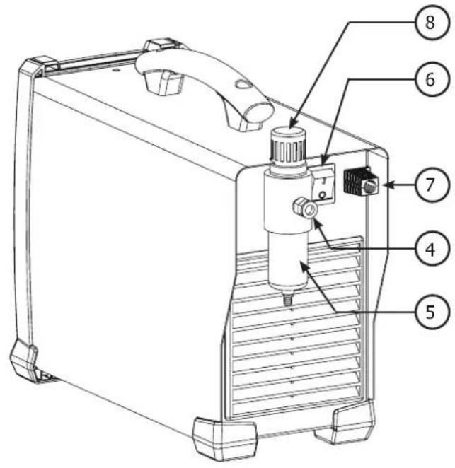
text_image
Technical diagram of a device with numbered parts labeled 4 through 8FIG-2
EASYCUT 25
text_image
EASY CUT 25 15 20 10 25 A bar 4,5 5,5 3,5 6,5 2,5" AIR TEST 6,5+ 8 6 5 7 4 INVERTER TECHNOLOGYEASYCUT 40
text_image
EASY CUT 40 INVERTER TECHNOLOGYINSTRUCTIONS DE SÉCURITÉ
CONSIGNE GENERALE

INSTALLATION – FONCTIONNEMENT PRODUIT
INTERFACE HOMME MACHINE (IHM) (FIG-2)
natural_image
Diagram showing two mechanical components with arrows indicating direction of movement (no text or symbols)natural_image
Simple line drawing of a tool gripping a clip against a straight line (no text or symbols)2 - VÉRIFIER LA PRÉSENCE DE TOUS LES CONSOMMABLES DE LA TORCHE ET BRANCHER COMME SUIT :
natural_image
Mechanical assembly diagram showing a shaft with labeled components A, B, and E (no text or symbols beyond labels)natural_image
Illustration of a hand holding a syringe with a tool, no text or symbols present
natural_image
Illustration of a hand holding a syringe with a dropper, no text or symbols present
natural_image
Illustration of a hand using a handheld tool to apply material on a flat surface (no text or symbols)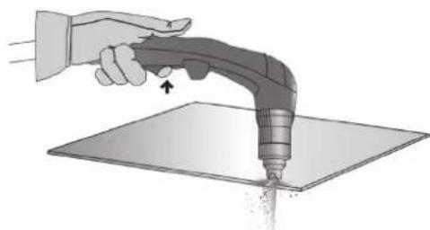
natural_image
Illustration of a hand using a handheld tool to apply material on a flat surface (no text or symbols)natural_image
Illustration of a hand using a handheld tool to apply material on a flat surface, with an arrow indicating direction (no text or symbols present)PERÇAGE D'UNE PIÈCE / DÉCOUPE EN MILIEU DE PIÈCE
natural_image
Illustration of a hand using a power tool to draw a 30-degree angle on a flat surface (no text or symbols)natural_image
Illustration of a hand using a handheld tool to apply material on a flat surface, with an arrow indicating the process (no text or symbols present)natural_image
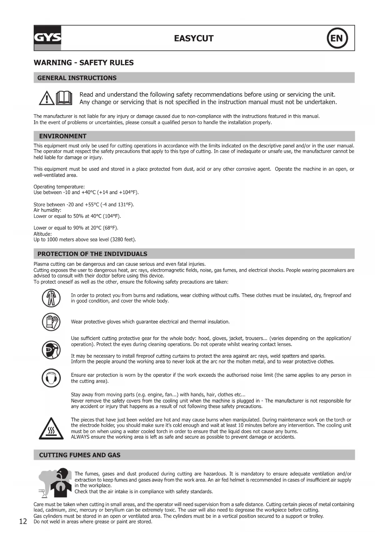
Illustration of a hand using a handheld tool to apply material on a flat surface (no text or symbols)Read and understand the following safety recommendations before using or servicing the unit. Any change or servicing that is not specified in the instruction manual must not be undertaken.
The manufacturer is not liable for any injury or damage caused due to non-compliance with the instructions featured in this manual. In the event of problems or uncertainties, please consult a qualified person to handle the installation properly.
ENVIRONMENT
This equipment must only be used for cutting operations in accordance with the limits indicated on the descriptive panel and/or in the user manual. The operator must respect the safety precautions that apply to this type of cutting. In case of inedaquate or unsafe use, the manufacturer cannot be held liable for damage or injury.
This equipment must be used and stored in a place protected from dust, acid or any other corrosive agent. Operate the machine in an open, or well-ventilated area.
Operating temperature:
Use between -10 and +40°C (+14 and +104°F).
Store between -20 and +55°C (-4 and 131°F).
Air humidity:
Lower or equal to 50% at 40°C (104°F).
Lower or equal to 90% at 20°C (68°F).
Altitude:
Up to 1000 meters above sea level (3280 feet).
PROTECTION OF THE INDIVIDUALS
Plasma cutting can be dangerous and can cause serious and even fatal injuries.
Cutting exposes the user to dangerous heat, arc rays, electromagnetic fields, noise, gas fumes, and electrical shocks. People wearing pacemakers are advised to consult with their doctor before using this device.
To protect oneself as well as the other, ensure the following safety precautions are taken:

In order to protect you from burns and radiations, wear clothing without cuffs. These clothes must be insulated, dry, fireproof and in good condition, and cover the whole body.

Wear protective gloves which guarantee electrical and thermal insulation.

Use sufficient cutting protective gear for the whole body: hood, gloves, jacket, trousers... (varies depending on the application/operation). Protect the eyes during cleaning operations. Do not operate whilst wearing contact lenses.

It may be necessary to install fireproof cutting curtains to protect the area against arc rays, weld spatters and sparks. Inform the people around the working area to never look at the arc nor the molten metal, and to wear protective clothes.
Ensure ear protection is worn by the operator if the work exceeds the authorised noise limit (the same applies to any person in the cutting area).
Stay away from moving parts (e.g. engine, fan...) with hands, hair, clothes etc...
Never remove the safety covers from the cooling unit when the machine is plugged in - The manufacturer is not responsible for any accident or injury that happens as a result of not following these safety precautions.
The pieces that have just been welded are hot and may cause burns when manipulated. During maintenance work on the torch or the electrode holder, you should make sure it's cold enough and wait at least 10 minutes before any intervention. The cooling unit must be on when using a water cooled torch in order to ensure that the liquid does not cause any burns.
ALWAYS ensure the working area is left as safe and secure as possible to prevent damage or accidents.
The fumes, gases and dust produced during cutting are hazardous. It is mandatory to ensure adequate ventilation and/or extraction to keep fumes and gases away from the work area. An air fed helmet is recommended in cases of insufficient air supply in the workplace.
Check that the air intake is in compliance with safety standards.
Care must be taken when cutting in small areas, and the operator will need supervision from a safe distance. Cutting certain pieces of metal containing lead, cadmium, zinc, mercury or beryllium can be extremely toxic. The user will also need to degrease the workpiece before cutting.
Gas cylinders must be stored in an open or ventilated area. The cylinders must be in a vertical position secured to a support or trolley.
Do not weld in areas where grease or paint are stored.
FIRE AND EXPLOSION RISKS
Protect the entire cutting area. Compressed gas containers and other inflammable material must be moved to a minimum safe distance of 11 meters.
A fire extinguisher must be readily available.
Be careful of spatter and sparks, even through cracks. It can be the source of a fire or an explosion.
Keep people, flammable objects and containers under pressure at a safe distance.
Cutting of sealed containers or closed pipes should not be undertaken, and if opened, the operator must remove any inflammable or explosive materials (oil, petrol, gas...).
Grinding operations should not be directed towards the device itself, the power supply or any flammable materials.
ELECTRIC SAFETY

The machine must be connected to an earthed electrical supply. Use the recommended fuse size.
An electrical discharge can directly or indirectly cause serious or deadly accidents.
Do not touch any live part of the machine (inside or outside) when it is plugged in (Torches, earth cable, cables, electrodes) because they are connected to the cutting circuit.
Before opening the device, it is imperative to disconnect it from the mains and wait 2 minutes, so that all the capacitors are discharged.
Do not touch the torch or electrode holder and earth clamp at the same time.
Damaged cables and torches must be changed by a qualified and skilled professional. Make sure that the cable cross section is adequate with the usage (extensions and cutting cables). Always wear dry clothes in good condition, in order to be insulated from the electrical circuit. Wear insulating shoes, regardless of the environment in which you work in.
EMC CLASSIFICATION

These Class A devices are not intended to be used on a residential site where the electric current is supplied by the public network, with a low voltage power supply. There may be potential difficulties in ensuring electromagnetic compatibility on these sites, because of the interferences, as well as radio frequencies.
This equipment does not comply with IEC 61000-3-12 and is intended to be connected to private low-voltage systems interfacing with the public supply only at the medium- or high-voltage level. On a public low-voltage power grid, it is the responsibility of the installer or user of the device to ensure, by checking with the operator of the distribution network, which device can be connected.

This equipment complies with the IEC 61000-3-11 standard.
ELECTROMAGNETIC INTERFERENCES
The electric currents flowing through a conductor cause electrical and magnetic fields (EMF). The cutting current generates an EMF field around the cutting circuit and the cutting equipment.
The EMF fields may disrupt some medical implants, such as pacemakers. Protection measures should be taken for people wearing medical implants. For example, access restrictions for passers-by or an individual risk evaluation for the welders.
All operators should take the following precautions in order to minimise exposure to the electromagnetic fields (EMF) generated by the cutting circuit::
- position the cutting cables together – if possible, attach them;
- keep your head and torso as far as possible from the cutting circuit;
- never enroll the cables around your body;
- never position your body between the cutting cables. Hold both cutting cables on the same side of your body;
- connect the earth clamp as close as possible to the area being welded;
- do not work too close to, do not lean and do not sit on the cutting machine.

People wearing pacemakers are advised to consult their doctor before using this device.
Exposure to electromagnetic fields while cutting may have other health effects which are not yet known.
RECOMMANDATIONS TO ASSES THE AREA AND CUTTING INSTALLATION
Overview
The user is responsible for installing and using the cutting equipment in accordance with the manufacturer's instructions. If electromagnetic disturbances are detected, it is the responsibility of the user of the cutting equipment to resolve the situation with the manufacturer's technical assistance. In some cases, this remedial action may be as simple as earthing the cutting circuit. In other cases, it may be necessary to construct an electromagnetic shield around the cutting power source and around the entire piece by fitting input filters. In all cases, electromagnetic interferences must be reduced until they are no longer bothersome.
Cutting area assessment
Before installing the machine, the user must evaluate the possible electromagnetic problems that may arise in the area where the installation is planned.
In particular, it should consider the following:
a) the presence of other power cables (power supply cables, telephone cables, command cable, etc...) above, below and on the sides of the arc cutting machine.
b) television transmitters and receivers ;
c) computers and other hardware;
d) critical safety equipment such as industrial machine protections;
e) the health and safety of the people in the area such as people with pacemakers or hearing aids;
f) calibration and measuring equipment
g) the isolation of the equipment from other machinery.
The user will have to make sure that the devices and equipments that are in the same room are compatible with each other. This may require extra precautions;
h) make sure of the exact hour when the cutting and/or other operations will take place.
The surface of the area to be considered around the device depends on the building's structure and other activities that take place there. The area taken in consideration can be larger than the limits determined by the companies.
Cutting area assessment
Besides the cutting area, the assessment of the cutting systems installation itself can be used to identify and resolve cases of disturbances. The assessment of emissions must include in situ measurements as specified in Article 10 of CISPR 11. In situ measurements can also be used to confirm the effectiveness of mitigation measures.
RECOMMENDATION ON METHODS OF ELECTROMAGNETIC EMISSIONS REDUCTION
a. National power grid: The arc cutting machine must be connected to the national power grid in accordance with the manufacturer's recommendation. If interferences occur, it may be necessary to take additional preventive measures such as the filtering of the power supply network. Consideration should be given to shielding the power supply cable in a metal conduit. It is necessary to ensure the shielding's electrical continuity along the cable's entire length. The shielding should be connected to the cutting current's source to ensure good electrical contact between the conduct and the casing of the cutting current source..
b. Maintenance of the cutting equipment: The cutting machine should be submitted to a routine maintenance check according to the manufacturer's recommendations. All accesses, service doors and covers should be closed and properly locked when the cutting equipment is on. The cutting equipment must not be modified in any way, except for the changes and settings outlined in the manufacturer's instructions. The spark gap of the arc start and arc stabilization devices must be adjusted and maintained according to the manufacturer's recommendations.
c. Cutting cables: Cables must be as short as possible, close to each other and close to the ground, if not on the ground.
d. Electrical bonding : consideration should be given to bonding all metal objects in the surrounding area. However, metal objects connected to the workpiece increase the riskof electric shock if the operator touches both these metal elements and the electrode. It is necessary to insulate the operator from such metal objects.
e. Earthing of the cutted part: When the part is not earthed - due to electrical safety reasons or because of its size and its location (which is the case with ship hulls or metallic building structures), the earthing of the part can, in some cases but not systematically, reduce emissions. It is preferable to avoid the earthing of parts that could increase the risk of injury to the users or damage other electrical equipment. If necessary, it is appropriate that the earthing of the part is done directly, but in some countries that do not allow such a direct connection, it is appropriate that the connection is made with a capacitor selected according to national regulations.
f. Protection and plating : The selective protection and plating of other cables and devices in the area can reduce perturbation issues. The protection of the entire cutting area can be considered for specific situations.
TRANSPORT AND TRANSIT OF THE CUTTING MACHINE

The machine is fitted with handle(s) to facilitate transportation. Be careful not to underestimate the machine's weight. The handle(s) cannot be used for slinging.
Do not use the cables or torch to move the machine. The cutting equipment must be moved in an upright position.
Do not place/carry the unit over people or objects.
A clear path is available when moving the item.
EQUIPMENT INSTALLATION
- Put the machine on the floor (maximum incline of 10^ .)
- Ensure the work area has sufficient ventilation for cutting, and that there is easy access to the control panel.
- The machine must not be used in an area with conductive metal dusts.
- The machine must be placed in a sheltered area away from rain or direct sunlight.
• The machine protection level is IP21, which means : - Protection against access to dangerous parts from solid bodies of a ≥12.5mm diameter and,
- Protection against vertically falling drops.
The power cables, extensions and cutting cables must be fully uncoiled to prevent overheating.

The manufacturer does not incur any responsibility regarding damages to both objects and persons that result from an incorrect and/or dangerous use of the machine.
MAINTENANCE / RECOMMENDATIONS


Ensure the machine is unplugged from the mains, and wait for two minutes before carrying out maintenance work. DANGER High Voltage and Currents inside the machine.
Maintenance should only be carried out by a qualified person. Annual maintenance is recommended.
1 - Air filter maintenance:
- It is necessary to periodically empty the air filter. To do so, press and hold the orange button below the filter.
- Disassembly:
- Unplug the air supply.
- Grab the tank, press the latch and rotate the bowl 45 degrees to the left.
- Pull the cube downwards and then put it down
- The filtering part is white, clean or replace it if necessary.
2 - Periodical maintenance:
- Periodically remove the cover and dust with an air gun. You are advised to have the electrical connections checked by a qualified person, with an insulated tool.
- Regularly check the condition of the power supply cable. If the power cable is damaged, it must be replaced by the manufacturer, an after sales service or a qualified person to prevent danger.
- Do not obstruct the machine's air intake, to allow air circulation.
- Check that the torch does not have any cracks or exposed wires.
- Check that the consumables are installed properly and not worn.
- Do not use this equipment to thaw pipes, to charge batteries, or to start any engine.
INSTALLATION – PRODUCT OPERATION
Only qualified personnel authorized by the manufacturer should perform the installation of the cutting equipment. During set up, the operator must ensure that the machine is unplugged. Connecting generators in a series or a parallel circuit is forbidden. It is recommended to use the cutting cables supplied with the unit in order to obtain the optimum product settings.
MACHINE SUPPLIED WITH
| EASYCUT 25 EASYCUT 40Ref. 065543 Ref. 029743 | ||
 |  |  |
| 4 m | TPT 25 TPT 40 | |
 |  |  |
 | ||
| Starting kit | [18*9] | [5*9] |
 |  |  |
| Pneumatic fittings | 8 mm 8 mm | |
Pneumatic fittings
TPT 25 TPT 40
The accessories supplies with the machine are to be used only with the same models.
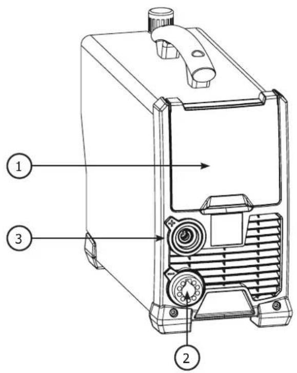
HARDWARE DESCRIPTION (FIG-1)
1- Keyboard + buttons 5- Air filter
2- Torch connector 6- On/off switch
3- Earth clamp connector 7- Power supply cable
4- Compressed air connector 8- Air regulator
(air pressure adjustment)
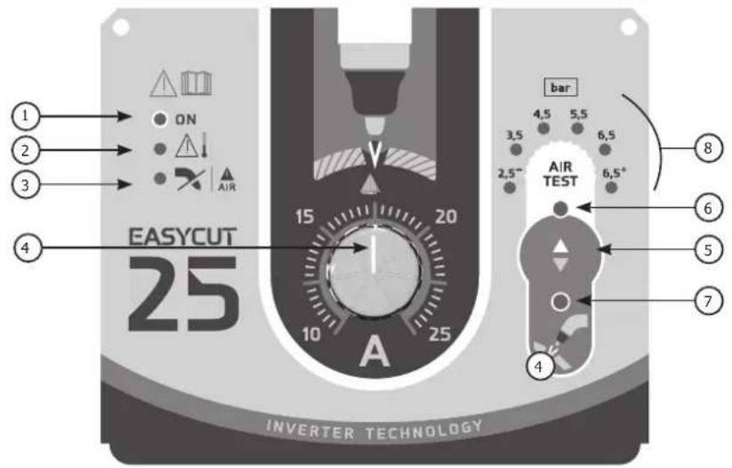
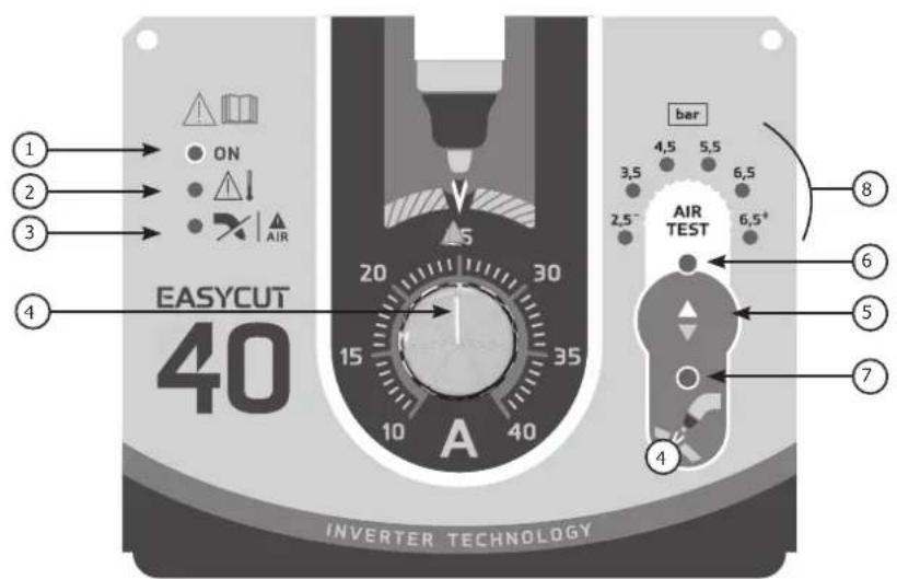
CONTROL BOARD (IHM) (FIG-2)
1- Power indicator (green)
2- Thermal protection and over current protection indicator (yellow)
3- Torch and air pressure fault light
4- Cutting current adjustment
5- Selection button (air pressure or cutting mode)
6- Air pressure selection indicator
7- Starting the cutting mode indicator
8- Indication to measured pressure value (LED).
POWER SUPPLY – STARTING UP
This machine is fitted with a 16A socket type CEE7/7 which must be connected to a single-phase 230V (50 - 60 Hz) power supply fitted with three wires and one earthed neutral. The absorbed effective current (I1eff) is indicated on the machine, for optimal use. Check that the power supply and its protection (fuse and/or circuit breaker) are compatible with the current required to run the machine (I1max). Use preferably a 32A plug with a 32A circuit-breaker for intensive use. Position the device so that the socket is always accessible.
They are power supplied by a 230V +/- 15% (50 - 60 Hz) EARTHED installation and are protected to work with generators. This hardware must only be used with a one phase electricity supply protected by a earthing wire.
The absorbed effective current (I1eff) is displayed on the machine, for optimal use. Check that the power supply and its protection (fuse and/or circuit breaker) are compatible with the current needed by the machine.
CONNECTION ON A GENERATOR
This product is not protected against overvoltages regularly emitted by generators and it is not recommended to connect it to this type of power supply.
USE WITH EXTENSION CABLES
All extension cables must have an adequate size and section, relative to the machine's voltage.
Use an extension that complies with national safety regulations.
| Voltage input Section of extension cable (<45m) | |
| 230 V 6 mm ^2 | |
AIR SUPPLY
The air supply can come from a compressor or high pressure bottles. A high pressure manometer must be used on any type of air supply and must be able to transport the gas to the plasma cutter. These machines come with an integrated air filter (5 m), but an extra filtering system can be necessary depending on the quality of the air supply (impurities filter in option, ref. 039728).

If the supplied air is of low quality, the cutting speed is reduced, the cutting quality deteriorates, the maximum cutting capacity diminishes and the life cycle of the consumables is reduced.
For optimal performance, the compressed air must comply with the standard ISO8573-1, class 1.2.2. The maximum vapor pressure point must be -40 °C. The maximum oil quantity (aerosol, liquid et vapor) must be 0.1 mg/m3.
natural_image
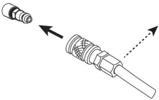
Technical illustration of a mechanical connector with two views: one showing a cylindrical component and the other showing a threaded shaft with internal mesh structure (no text or symbols)Connecting the gas supply to the current source by means of an inert gas pipe of an internal diameter of 9.5 mm and a quick connect coupler.
The pressure must not exceed 9 bars, The filter's cuve could expose.
The recommended entry pressure during air circulation is 2.5 to 6.5 bars with a minimum of 115 L/min.
TORCH SETUP
The torches are cooled with ambient air and do not require any special cooling.
1 - CONSUMABLES LIFE CYCLE
The replacement frequency of the Plasma's consumables depends on several factors:
- The metal thickness.
• The average cutting time - The air quality (presence of oil, humidity or other contaminants).
- The metal piercing or the cut from the edge.
- The adequate distance between the torch and the part when cutting.
In normal conditions :
- During manual cutting, the electrode wears out first.
Torch consumables :
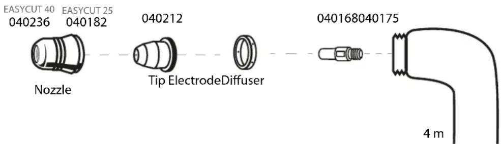
text_image
EASYCUT 40 EASYCUT 25 040236 040182 Nozzle Tip ElectrodeDiffuser 040168040175 4 m2 - INSTALLATION OF THE TORCH CONSUMABLES :

Before changing the consumables, cut the power supply using the interrupor behind the machine.
To use the torch, a complete set of consumables must be installed in the correct order: electrode, diffuser, tip and nozzle.
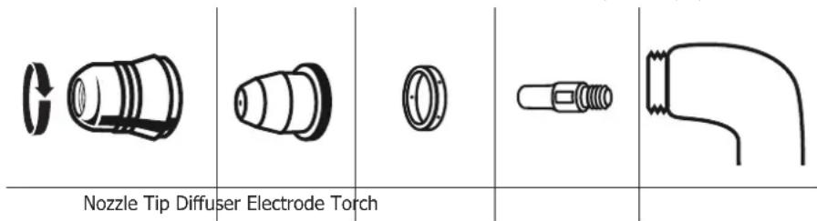
text_image
Nozzle Tip Diffuser Electrode TorchMACHINE OPERATION
1 - PLACE THE EARTH CLAMP ON THE PART TO CUT
Ensure proper electrical contact and do not to put the cable on the cutting trajectory.
Warning: painting prevents contact between the metal part and the earth clamp, do not forget to sand.
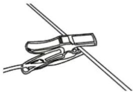
natural_image
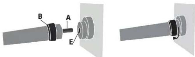
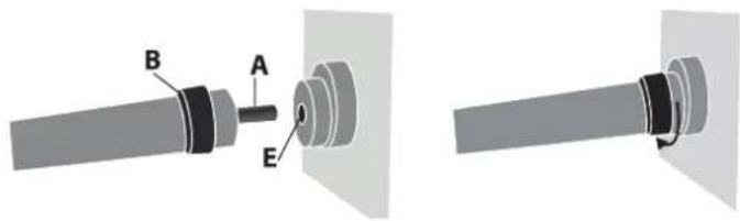
Simple line drawing of a hand holding a clip against a diagonal line (no text or symbols)2 - CHECK THE PRESENCE OF ALL THE CONSUMABLES ON THE TORCH AND CONNECT AS FOLLOWS :
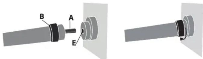
text_image
Technical diagram showing mechanical assembly with labeled parts A, B, and EInsert the torch's connector (A) in the female compartment (E) and screw the B part. Be careful to tighten the torch.
To remove the torch, unscrew in the same manner as above.
3 - START THE MACHINE and check that the power light (1) is on.
4 - SETTINGS PANEL (FIG-2)

ON Green light (1) «ON»
When the machine is switched on the light turns on. In case of power failure, the green light goes off but the device remains powered while the power cable is unplugged.


Orange light (2)
Over-temperature: in such a case, the orange light will flash once per second. You shall wait a few minutes, the light will turn off and the machine will start to work again.
Over-current on primary circuit: in such a case, the orange light will turn on all the time. You shall switch off the machine (with the main switch) and switch on.


Orange light (3)
No connection of torch: in such a case, the orange light will turn on all the time. You shall check the connection of torch and the protection shroud. No air or Not enough pressure: in such case, the orange light will flash once per second. You shall check the air and adjust the pressure of air more than 2.5 bar and you also need to check the tailpipe was not twisted.
5 - SETTING FOR THE AIR PRESSURE (FIG-2)
Push the button set select. Choose the air pressure between 2.5 and 6.5 bar.
6 - CURRENT SETTING (FIG-2)
Use the adjuster to set the current relative to the thickness and type of the metal sheet. Refer to the «guideline printed on the serigraphy of cutting the machine
7 - STARTING THE CUTTING MODE (FIG-2)
Push the button and select to begin cutting.
SAFETY TRIGGER
The torch is equipped with a safety latch to prevent accidental use: Unlock it and pull the trigger as below:
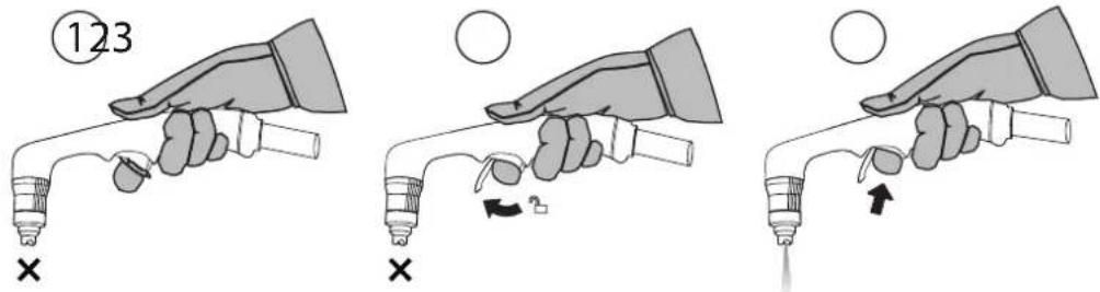

Wear appropriate protective equipment. Stay away from the tip of the torch. Keep your hands away from the cutting trajectory. Never point the torch towards you or another person.
TIPS FOR CUTTING
- Lightly drag the tip on the part for an even cut. This will guarantee a constant, adapted distance.
- When cutting, ensure that the sparks come from the bottom of the part. The sparks should lag slightly behind the torch when cutting (angle of 15^ to 30^ from the vertical).
- If the sparks fly from the top of the part, slow the movement, or set the output current to a higher level.
- For straight cuts, use a ruler as a guide.
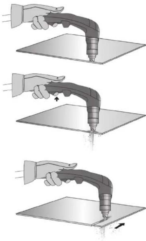
MANUAL CUT FROM THE EDGE OF THE PART
① With the earth clamp is fastened to the part, maintain the torch's tip perpendicularly (90°) to the edge of the part.
② Press the torch's trigger to start the arc until this one has completely cut into the part.
③ Once the part is cut, slightly drag the tip on the part to continue the cut. Try to maintain a regular rythmn.
natural_image
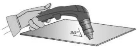
Three-step illustration showing a hand using a handheld tool to lift a surface, with no text or symbols present.PART PIERCING / CUT IN THE MIDDLE OF THE PART
① With the earth clamp is fastened to the part, maintain the torche at an angle of roughly 30^ to the part.
② Press the torch's trigger to start the arc while maintaining an angle of 30^ to the part. Slowly rotate the torch towards a perpendicular position ( 90^ ).
③ Immobilise the torch while keeping the trigger pressed. If the sparks come from below the part, the arc has cut the material.
natural_image
Illustration of a hand using a power tool to apply 30-degree angle on a flat surface (no text or symbols)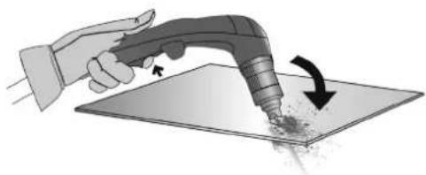
natural_image
Illustration of a hand using a handheld tool to apply material on a flat surface, with an arrow indicating the process (no text or symbols present)
natural_image
Illustration of a hand using a handheld tool to apply material onto a flat surface (no text or symbols)④ Once the part is cut, slightly drag the tip on the part to continue the cut. Try to maintain a regular rythmn.
CONSUMABLES INSPECTION (ASSEMBLY AND DISASSEMBLY, SEE P.16)
| Parts Actions Solutions | ||||
 Nozzle Nozzle | Check the for damage and surface wear. | Replace the nozzle when it looks damaged (traces of burns). | ||
 Tip Tip | Visually check the tip's internal hole. | OK NOK | NOK | Replace the tip if the inner diameter is enlarged or distorted. |
| [OTWS]Diffuser | Check for damage and wear on the surface and inside the diffuser.Check that the fumes' exhausts are not obstructed. | Replace the diffuser if the surface is damaged or worn, or if fume exhausts are obstructed. | ||
 Electrode Electrode | Visually check the electrode's internal hole. | OK | NOK | Replace electrode when the insert is used (removal of 1.5 mm). |
ANOMALIES, SOLUTIONS
| PROBLEMS SOLUTIONS | |
| The machine does not switch on. | - Check that the power cord is plugged to the mains properly.- Check that the device is powered on the main circuit breaker panel or power supply box .- Check that the voltage is not too low (More than 15% below nominal voltage).- Check that the circuit breaker didn't activate. |
| The pilot arc switches off | - Worn consumables- No electrical contact between the tailpipe and the electrode. |
| The cutting arc stops. | - Cutting speed is too low.- Bad earth clamp connection.- Cutting height too high. |
| Insufficient penetration. | - Cutting speed too fast.- Not enough current.- Part is too thick. |
| The arc sprays and whistles. | - Purge the air filter.- The filtering cartridge must be cleaned or replaced. |
WARRANTY
The warranty covers faulty workmanship for 2 years from the date of purchase (parts and labour).
The warranty does not cover:
- Transit damage.
- Normal wear of parts (eg. : cables, clamps, etc..).
- Damages due to misuse (power supply error, dropping of equipment, disassembling).
- Environment related failures (pollution, rust, dust).
In case of failure, return the unit to your distributor together with:
- The proof of purchase (receipt etc ...)
- A description of the fault reported
natural_image
Diagram showing two types of connectors: a cylindrical component and a threaded connector with dashed arrows indicating direction (no text or symbols)natural_image
Simple line drawing of a tool gripping a clip against a diagonal line (no text or symbols)text_image
Technical diagram showing a mechanical assembly with labeled components A, B, and Enatural_image
Illustration of a hand using a handheld tool to apply material on a flat surface (no text or symbols)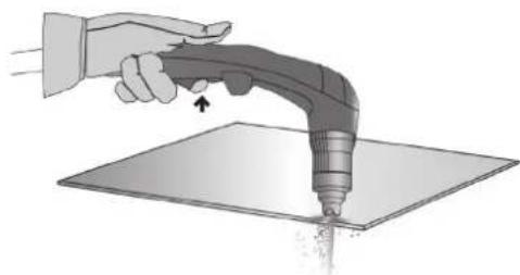
natural_image
Illustration of a hand using a handheld tool to apply material on a flat surface (no text or symbols)natural_image
Illustration of a hand using a handheld tool to press or brush on a flat surface, with motion arrows indicating movement (no text or symbols)natural_image
Illustration of a hand using a power tool to cut a 30-degree angle on a flat surface (no text or symbols)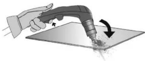
natural_image
Illustration of a hand using a handheld tool to apply material to a flat surface, with an arrow indicating the process (no text or symbols present)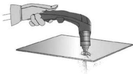
natural_image
Illustration of a hand using a handheld tool to apply material onto a flat surface (no text or symbols)INSPEKTION DER VERSCHLEISSTEILE (MONTAGE UND DEMONTAGE, SIEHE S. 26)
natural_image
Diagram showing two mechanical connectors with directional arrows indicating movement or assembly (no text or symbols)natural_image
Simple line drawing of a tool gripping a cable or wire (no text or symbols)natural_image
Mechanical assembly diagram showing a shaft connected to a housing with labeled points A, B, and E (no text or symbols beyond labels)natural_image
Illustration of a hand holding a syringe with a tool, no text or symbols present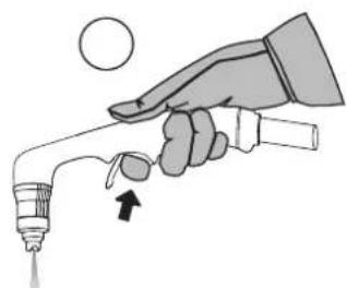
natural_image
Illustration of a hand holding a syringe with a dropper, no text or symbols present
natural_image
Illustration of a hand using a handheld tool to apply material on a flat surface (no text or symbols)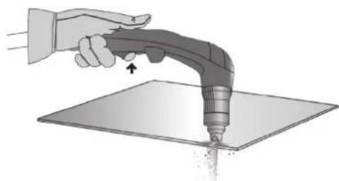
natural_image
Illustration of a hand using a handheld tool to apply material on a flat surface (no text or symbols)natural_image
Illustration of a hand using a handheld tool to press or mark a surface (no text or symbols present)natural_image
Illustration of a hand using a power tool to cut a 30-degree angle on a flat surface (no text or symbols)natural_image
Illustration of a hand using a handheld tool to apply material on a flat surface, with an arrow indicating the process (no text or symbols present)natural_image
Illustration of a hand using a handheld tool to press or brush on a flat surface (no text or symbols)natural_image
Diagram showing two mechanical components with arrows indicating direction of movement (no text or symbols)natural_image
Simple line drawing of a cable being held by two clamps (no text or symbols)text_image
Technical diagram showing mechanical assembly with labeled parts A, B, and Enatural_image
Illustration of a hand holding a syringe with a tool, no text or symbols present
natural_image
Illustration of a hand holding a syringe with an arrow indicating force (no text or symbols)
natural_image
Illustration of a hand holding a welding torch touching a flat sheet of paper (no text or symbols)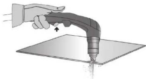
natural_image
Illustration of a hand using a handheld tool to apply material on a flat surface (no text or symbols)natural_image
Illustration of a hand using a handheld tool to apply material on a flat surface, with an arrow indicating direction (no text or symbols present)natural_image
Illustration of a hand using a handheld tool to draw a 30-degree angle on a flat surface (no text or symbols present)natural_image
Illustration of a hand using a handheld tool to apply material to a flat surface, with an arrow indicating the process (no text or symbols present)natural_image
Illustration of a hand using a handheld tool to apply material on a flat surface (no text or symbols)APPARAAT WORDT GELEVERD MET
| EASYCUT 25 EASYCUT 40Ref. 065543 Ref. 029743 | ||
| 4 m | √TPT 25 TPT 40 | √ |
| 2 m - 10 mm ^2 | √ | √ |
| Starter set | - | - |
| pneumatische fittingen | √8 mm 8 mm | √ |
BESCHRIJVING VAN HET APPARAAT (FIG. I)
MAN MACHINE INTERACTION (MMI) (FIG-2)
natural_image
Technical illustration of a mechanical connector with two views: one showing a cylindrical component and the other showing a threaded shaft with internal mesh structure (no text or symbols)WERKING VAN DE GENERATOR
natural_image
Simple line drawing of a tool gripping a cable or wire (no text or symbols)2 - CONTROLEER DE AANWEZIGHEID VAN ALLE SLIJTDELEN VAN DE TOORTS EN MONTEER DEZE ALS VOLGT :
natural_image
Mechanical assembly diagram showing a shaft with labeled components A, B, and E, connected to a housing (no text or symbols beyond labels)natural_image
Illustration of a hand holding a syringe with a valve and a circular object above, no text or symbols present.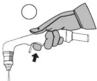
natural_image
Illustration of a hand holding a syringe with a droplet and arrow indicating motion (no text or symbols)
natural_image
Illustration of a hand using a handheld tool to apply material on a flat surface (no text or symbols)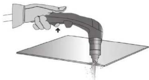
natural_image
Illustration of a hand using a handheld tool to apply material on a flat surface (no text or symbols)natural_image
Illustration of a hand using a handheld tool to press or mark a surface, with an arrow indicating motion (no text or symbols present)HET WERKSTUK DOORBOREN / SNIJDEN IN HET MIDDEN VAN HET WERKSTUK
natural_image
Illustration of a hand using a power tool to draw a 30-degree angle on a flat surface (no text or symbols present)natural_image
Illustration of a hand using a handheld tool to apply material to a surface, with an arrow indicating rotation (no text or symbols present)natural_image
Illustration of a hand using a handheld tool to apply material on a flat surface (no text or symbols)natural_image
Technical illustration of a mechanical connector with two views: one showing a cylindrical component and the other showing a threaded shaft with internal mesh structure (no text or symbols)natural_image
Mechanical assembly diagram showing a shaft with labeled components A, B, and E (no text or symbols beyond labels)natural_image
Illustration of a hand holding a handheld electric welding torch over a flat sheet of paper (no text or symbols)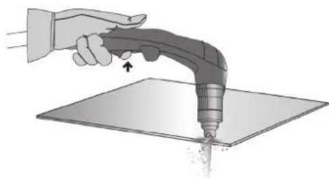
natural_image
Illustration of a hand using a handheld tool to apply material on a flat surface (no text or symbols)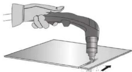
natural_image
Illustration of a hand using a power tool to press or mark a surface (no text or symbols present)natural_image
Illustration of a hand using a power tool to apply 30-degree angle on a flat surface (no text or symbols)natural_image
Illustration of a hand using a handheld tool to apply material to a surface, with an arrow indicating the process (no text or symbols present)natural_image
Illustration of a hand using a handheld tool to apply material onto a flat surface (no text or symbols)text_image
Technical diagram of a portable electronic device with numbered components and internal wiring layout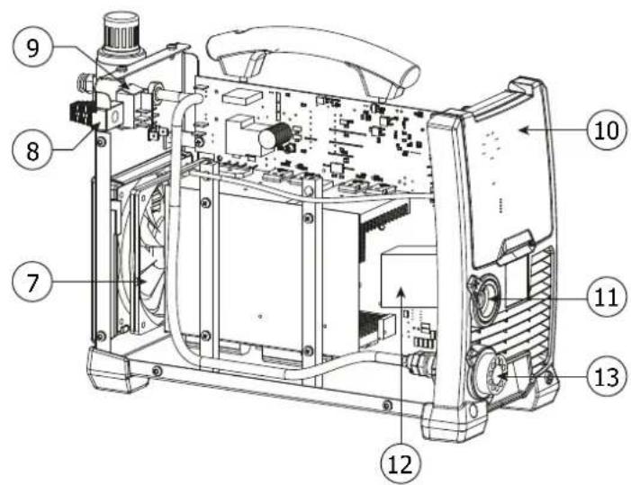
text_image
Technical diagram of a mechanical device with numbered components for identification| 1 | Carte Principale / Main board / Hauptplatine / Tarjeta principal / Основная Плата / Hoofd printplaat / Carta principale | 53580 |
| 2 | Face avant plastique / Front face plastic / Vorderseite Kunststoff / Parte frontal de plástico / Пластиковый молдинг на передней панели / Voorzijde kunststof / Frontale in plastica | 56164 |
| 3 | Carte PCBA / Panel PCBA / Platine PCBA / Tarjeta PCBA / Плата PCBA / PCBA kaart / Scheda PCBA | 53581 |
| 4 | Poignée en plastique / Plastic handle / Kunststoffgriff / Mango de plástico / Пластиковая ручка / Kunststoffen handvat / Impugnatora in plastica | 56048 |
| 5 | Filtre & manodétendeur / Filter & regulator / Filter & Druckluftmesser / Filtro y manorreductor / Фильтр и редуктор / Filter en drukregelaar / Filtro & riduttore di pressione | 53582 |
| 6 | Grille en plastique / Plastic grill / Kunststoffgitter / Rejilla de plástico / Пластмассовая решетка / Kunststoffen rooster / Griglia in plastica | 51010 |
| 7 | Ventilateur / Fan / Ventilator / Ventilador / Вентилятор / Ventilator / Ventilatore | 53586 |
| 8 | Câble d'alimentation / Main cable / Versorgungskabel / Cable de alimentación eléctrica / Шнур питания / Voedingskabel / Cavo di alimentazione | 21464 |
| 9 | Interrupteur / switch / Schalter / Interruptor / Выключатель / Schakelaar / Interruttore | 53546 |
| 10 | Boîtier de protection / Protective casing / Schutzgehäuse / Carcasa de protección / Защитное стекло / Behuizing / Involucro di protezione | 56166 |
| 11 | Connecteur de pince de masse 1/4 / 1/4 earth clamp connector / Stecker der Masseklemme 1/4 / Conector de pinza de masa 1/4 / Коннектор для зажима массы 1/4 / Aansluiting massaklem 1/4 / Connettore del morsetto di massa 1/4 | 53583 |
| 12 | Inducteur de sortie / Output inductor / Ausgangsindikator / Inductor de salida / Выходной индуктор / Uitgangsinductor / Induttore di uscita | 53584 |
| 13 | Raccord de torche / Torch connector / Brenneranschluss / Conector de antorcha / Коннектор для горелки / Aansluiting toorts / Raccordo torcia | 53585 |
| Corps de torche / Torch body / Brennerkörper / Cuerpo de la antorcha / Корпус резака / Toorts lichaam / Corpo torcia | 71967 |
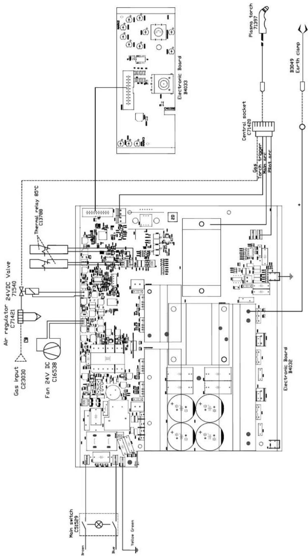
SCHÉMA ÉLECTRIQUE / ELECTRICAL DIAGRAM / SCHALTPLAN / ESQUEMA ELÉCTRICO / ELEKTRISCH SCHEMA
EASYCUT 25
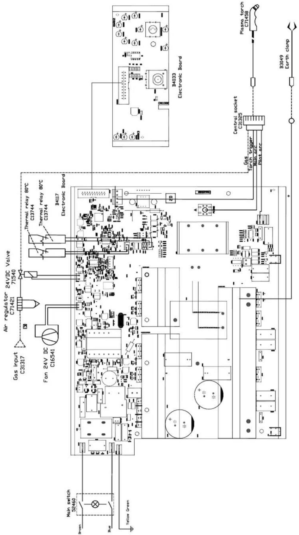
text_image
Gas input C31317 Air regulator C71421 24VDC Valve 71540 Fan 24V DC C16541 Thermal relay 80°C C13744 Thermal relay 80°C C13744 B4117 Electronic Board Main switch 52460 Brown Blue Yellow Green B4033 Electronic Board Gas Torch trigger Central socket C31325 Plasma torch C71458 Plat arc B3049 Earth clampSCHÉMA ÉLECTRIQUE / ELECTRICAL DIAGRAM / SCHALTPLAN / ESQUEMA ELÉCTRICO / ELEKTRISCH SCHEMA
EASYCUT 40