
VR001G - Power Tools MAKITA - Free user manual and instructions
Find the device manual for free VR001G MAKITA in PDF.
User questions about VR001G MAKITA
0 question about this device. Answer the ones you know or ask your own.
Ask a new question about this device
Download the instructions for your Power Tools in PDF format for free! Find your manual VR001G - MAKITA and take your electronic device back in hand. On this page are published all the documents necessary for the use of your device. VR001G by MAKITA.
USER MANUAL VR001G MAKITA
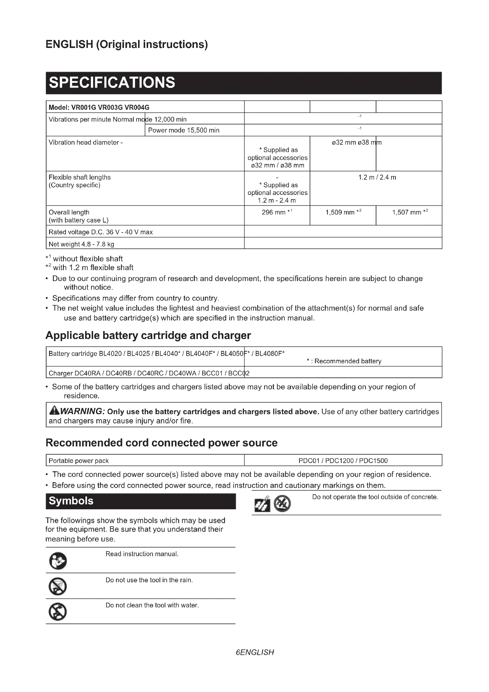
| Model: VR001G VR003G VR004G | ||||
| Vibrations per minute Normal mode | de 12,000 min | -1 | ||
| Power mode 15,500 min | -1 | |||
| Vibration head diameter - | * Supplied as optional accessoriesø32 mm /ø38 mm | ø32 mmø38 mm | ||
| Flexible shaft lengths(Country specific) | - * Supplied as optional accessories1.2 m - 2.4 m | 1.2 m / 2.4 m | ||
| Overall length(with battery case L) | 296 mm *1 | 1,509 mm *2 | 1,507 mm *2 | |
| Rated voltage D.C. 36 V - 40 V max | ||||
| Net weight 4.8 - 7.8 kg | ||||
^1 without flexible shaft
^2 with 1.2m flexible shaft
- Due to our continuing program of research and development, the specifications herein are subject to change without notice.
- Specifications may differ from country to country.
- The net weight value includes the lightest and heaviest combination of the attachment(s) for normal and safe use and battery cartridge(s) which are specified in the instruction manual.
Applicable battery cartridge and charger
| Battery cartridge BL4020 / BL4025 / BL4040* / BL4040F* / BL4050 | * / BL4080F* *: Recommended battery |
| Charger DC40RA / DC40RB / DC40RC / DC40WA / BCC01 / BCC02 |
- Some of the battery cartridges and chargers listed above may not be available depending on your region of residence.
WARNING: Only use the battery cartridges and chargers listed above. Use of any other battery cartridges and chargers may cause injury and/or fire.
Recommended cord connected power source
| Portable power pack | PDC01 / PDC1200 / PDC1500 |
- The cord connected power source(s) listed above may not be available depending on your region of residence.
- Before using the cord connected power source, read instruction and cautionary markings on them.
Symbols
The followings show the symbols which may be used for the equipment. Be sure that you understand their meaning before use.

Read instruction manual.

Do not use the tool in the rain.

Do not clean the tool with water.


Do not operate the tool outside of concrete.
Due to the presence of hazardous components in the equipment, waste electrical and electronic equipment, accumulators and batteries may have a negative impact on the environment and human health. Do not dispose of electrical and electronic appliances or batteries with household waste!
In accordance with the European Directive on waste electrical and electronic equipment and on accumulators and batteries and waste accumulators and batteries, as well as their adaptation to national law, waste electrical equipment, batteries and accumulators should be stored separately and delivered to a separate collection point for municipal waste, operating in accordance with the regulations on environmental protection.
This is indicated by the symbol of the crossed-out wheeled bin placed on the equipment.
Intended use
The tool is intended for removing bubbles from concrete when casting concrete.
Noise
The typical A-weighted noise level determined according to ENIEC62841-2-12:
Model VR001G
Sound pressure level (L_pA):70dB(A) or less
Uncertainty (K) : 3 dB (A)
Model VR003G
The noise level under working may exceed 80 dB (A).
NOTE: The declared noise emission value(s) has been measured in accordance with a standard test method and may be used for comparing one tool with another.
NOTE: The declared noise emission value(s) can also be used in a preliminary assessment of exposure.

WARNING: Wear ear protection.
WARNING: The noise emission during actual use of the power tool can differ from the declared total value(s) depending on the ways in which the tool is used.
WARNING: Be sure to identify safety measures to protect the operator that are based on an estimation of exposure in the actual conditions of use (taking account of all parts of the operating cycle such as the times when the tool is switched off and when it is running idle in addition to the trigger time).
Vibration
The continuous vibration total value (tri-axial vector sum) determined according to ENIEC62841-2-12:
Model VR001G
Work mode: load with flexible hose
Vibration emission (a_h):6.2~m / s^2
Uncertainty (K): 1.5m / s^2
Model VR003G
Work mode: load with flexible hose
Vibration emission (a_h):6.2~m / s^2
Uncertainty (K): 1.5m / s^2
Model VR004G
Work mode: load with flexible hose
Vibration emission (a_h):6.2m / s^2
Uncertainty (K): 1.5m / s^2
NOTE: The declared vibration total value(s) has been measured in accordance with a standard test method and may be used for comparing one tool with another.
NOTE: The declared vibration total value(s) can also be used in a preliminary assessment of exposure.

WARNING: The vibration emission during actual use of the power tool can differ from the declared total value(s) depending on the ways in which the tool is used.

WARNING: Be sure to identify safety measures to protect the operator that are based on an estimation of exposure in the actual conditions of the tire (taking account of all parts of the operating cycle such as the times when the tool is switched off and when it is running idle in addition to the trigger time).
The following shows the mean values of the peak amplitude of the acceleration from repeated shock vibrations, p_F , with corresponding uncertainty (K) determined according to ENIEC62841-2-12.
Model VR001G
Work mode: load with flexible hose
p_F:248 ~m / s^2
Uncertainty (K): 11m / s^2
Model VR003G
Work mode: load with flexible hose
p_F:248 ~m / s^2
Uncertainty (K): 11m / s^2
Model VR004G
Work mode: load with flexible hose
p_F:248m / s^2
Uncertainty (K): 11m / s^2
NOTE: These declared values should not be used to determine hand arm vibration exposure.
Declarations of Conformity
For European countries only
The EU Declaration of Conformity can be accessed from the following URL.
https://support makita.biz/doc/doc_index.html
For the UK
The Declaration of conformity is included in Annex A to this instruction manual.
SAFETYWARNINGS
General power tool safety warnings
WARNING Read all safety warnings, instructions, illustrations and specifications provided with this power tool. Failure to follow all instructions listed below may result in electric shock, fire and/or serious injury.
Save all warnings and instructions for future reference.
The term "power tool" in the warnings refers to your mains-operated (corded) power tool or battery-operated (cordless) power tool.
Cordless concrete vibrator safety warnings
- Always keep your hands and face away from vibrating head when operating.
- Switch off the tool immediately if you notice abnormal noise or something faulty during operation.
- Inspect the tool carefully for breakage, cracks or deformation if you accidentally drop it or strike it against something.
- Do not carry the tool with finger on switch.
- Do not set the tool down and switch it on. The vibrating head may whip around out of control and cause an accident.
- Be careful not to allow water, wet concrete or the like to get into the tool. Do not let the tool fall into wet concrete.
- Insert the vibrating head carefully between iron/steel frames or reinforcing rods not to come in contact with them.
- Do not crush or twist the flexible hose.
- Do not overly bend the flexible hose.
- Use a wet cloth or the like to carefully wipe off any wet concrete left on the tool after use. Extra care should be given to thorough cleaning of the vents, switch area, cover openings, etc.
- Do not use the tool in the rain. Do not clean the tool in water.
-
After operating the tool, switch off the tool and wait until the vibration of the flexible shaft stops completely before putting down the tool.
-
After operating the tool, do not touch the vibrating part as it may be extremely hot and could burn your skin.
- Do not operate the tool outside of concrete. The vibrating part is cooled down by inserting the vibrating part into concrete.
- If the power is cut off due to power failure or the disconnection of power plug, set the switch to the off position.
SAVE THESE INSTRUCTIONS.
WARNING: DO NOT let comfort or familiarity with product (gained from repeated use) replace strict adherence to safety rules for the subject product. MISUSE or failure to follow the safety rules stated in this instruction manual may cause serious personal injury.
Important safety instructions for battery cartridge
- Before using battery cartridge, read all instructions and cautionary markings on (1) battery charger, (2) battery, and (3) product using battery.
- Do not disassemble or tamper with the battery cartridge. It may result in a fire, excessive heat, or explosion.
- If operating time has become excessively shorter, stop operating immediately. It may result in a risk of overheating, possible burns and even an explosion.
- If electrolyte gets into your eyes, rinse them out with clear water and seek medical attention right away. It may result in loss of your eyesight.
- Do not short the battery cartridge:
(1) Do not touch the terminals with any conductive material.
(2) Avoid storing battery cartridge in a container with other metal objects such as nails, coins, etc.
(3) Do not expose battery cartridge to water or rain. A battery short can cause a large current flow, overheating, possible burns and even breakdown.
- Do not store and use the tool and battery cartridge in locations where the temperature may reach or exceed 50^ (122^)
- Do not incinerate the battery cartridge even if it is severely damaged or is completely worn out. The battery cartridge can explode in a fire.
- Do not nail, cut, crush, throw, drop the battery cartridge, or hit against a hard object to the battery cartridge. Such conduct may result in a fire, excessive heat, or explosion.
- Do not use a damaged battery.
- The contained lithium-ion batteries are subject to the Dangerous Goods Legislation requirements.
For commercial transports e.g. by third parties, forwarding agents, special requirement on packaging and labeling must be observed.
For preparation of the item being shipped, consulting an expert for hazardous material is required. Please also observe possibly more detailed national regulations.
Tape or mask off open contacts and pack up the battery in such a manner that it cannot move around in the packaging.
- When disposing the battery cartridge, remove it from the tool and dispose of it in a safe place. Follow your local regulations relating to disposal of battery.
- Use the batteries only with the products specified by Makita. Installing the batteries to non-compliant products may result in a fire, excessive heat, explosion, or leak of electrolyte.
- If the tool is not used for a long period of time, the battery must be removed from the tool.
- During and after use, the battery cartridge may take on heat which can cause burns or low temperature burns. Pay attention to the handling of hot battery cartridges.
- Do not touch the terminal of the tool immediately after use as it may get hot enough to cause burns.
- Do not allow chips, dust, or soil stuck into the terminals, holes, and grooves of the battery cartridge. It may cause heating, catching fire, burst and malfunction of the tool or battery cartridge, resulting in burns or personal injury.
- Unless the tool supports the use near high-voltage electrical power lines, do not use the battery cartridge near high-voltage electrical power lines. It may result in a malfunction or breakdown of the tool or battery cartridge.
- Keep the battery away from children. SAVE THESE INSTRUCTIONS.
CAUTION: Only use genuine Makita batteries. Use of non-genuine Makita batteries, or batteries that have been altered, may result in the battery bursting causing fires, personal injury and damage. It will also void the Makita warranty for the Makita tool and charger.
NOTICE: Makita is not responsible for any accidents resulting from the use of non-genuine Makita batteries or batteries that have been modified. Genuine Makita batteries have been rigorously evaluated for compatibility with Makita tools and chargers, in line with applicable legislation and safety standards.
Tips for maintaining maximum battery life
- Charge the battery cartridge before completely discharged. Always stop tool operation and charge the battery cartridge when you notice less tool power.
- Never recharge a fully charged battery cartridge. Overcharging shortens the battery service life.
-
Charge the battery cartridge with room temperature at 10^ - 40^ (50°F - 104°F). Let a hot battery cartridge cool down before charging it.
-
When not using the battery cartridge, remove it from the tool or the charger.
- Charge the battery cartridge if you do not use it for a long period (more than six months).
FUNCTIONAL DESCRIPTION
CAUTION: Always be sure that the tool is switched off and the battery cartridge is removed before adjusting or checking function on the tool.
Replacing battery case
Optional accessory
Fig.1: 1.Standard equipped battery case 2.Screws 3.Housing
- Open the standard equipped battery case while pressing the buttons on sides of the case.
- Loosen the screws securing the standard equipped battery case, and slide the battery case off along the housing.
- Slide an optional battery case into the tool. Open the case while pressing the buttons on sides of the case. Then tighten the screws to secure it in place.
Fig.2: 1. Optional battery case 2. Screws
4. Close the battery case securely.
Installing and removing battery cartridge
CAUTION: Before installing and removing battery cartridge, always make sure to set the switch trigger back into the "OFF" position by pulling the switch trigger fully and releasing it.
CAUTION: Hold the tool and the battery cartridge firmly when installing or removing battery cartridge. Failure to hold the tool and the battery cartridge firmly may cause them to slip off your hands and result in damage to the tool and battery cartridge and a personal injury.
CAUTION: Always install the battery cartridge fully until the red indicator cannot be seen. If not, it may accidentally fall out of the tool, causing injury to you or someone around you.
CAUTION: Do not install the battery cartridge forcibly. If the cartridge does not slide in easily, it is not being inserted correctly.
CAUTION: Take care not to trap your fingers between the battery case and its front cover while installing and removing battery cartridge.
Installation
-
Open the battery case while pressing the buttons on sides of the battery case.
Fig.3: 1. Battery case 2. Buttons -
Insert a battery cartridge in place aligning its
tongue with the groove on the tool. If you can see the red indicator as shown in the figure, it is not locked completely.
Fig.4: 1. Red indicator 2. Battery cartridge
3. Close the battery case securely.
Uninstallation
- Open the battery case while pressing the buttons on sides of the battery case.
- Slide the battery cartridge off from the tool while pressing the button on front of the battery cartridge.
Fig.5: 1. Button 2. Battery cartridge
3. Close the battery case securely.
For cord connected power source
Optional accessory
Replace the standard equipped battery case with an optional battery case H before installation.
Installation
- Open the battery case while pressing the buttons on sides of the battery case.
- Insert a battery adapter in place aligning its tongue with the groove on the tool. If you can see the red indicator as shown in the figure, it is not locked completely.
Fig.6: 1. Red indicator 2. Battery adapter
3. Open the rubber sealing grommet in the battery case.
Make sure to squeeze the rubber sealing grommet out of the round hole rim from inside the front cover of the case.
Fig.7: 1. Rubber sealing grommet 2. Front cover
4. Pass the adapter plug and plug cord through the round hole in the battery case.
Fig.8: 1. Adapter plug 2. Plug cord 3. Battery adapter
5. Close the battery case securely.
6. Place the rubber sealing grommet back in place.
Fig.9: 1. Rubber sealing grommet 2. Plug cord 3. Battery case
Uninstallation
- Open the battery case while pressing the buttons on sides of the battery case.
- Open the rubber sealing grommet in the battery case.
Make sure to squeeze the rubber sealing grommet out of the round hole rim from inside the front cover of the case.
Fig.10: 1. Rubber sealing grommet 2. Front cover
3. Pull the adapter plug and plug cord out through the round hole in the battery case.
4. Slide the battery adapter off from the tool while pressing the button on front of the battery adapter.
5. Close the battery case securely.
Indicating the remaining battery capacity
Press the check button on the battery cartridge to indicate the remaining battery capacity. The indicator lamps light up for a few seconds.
Fig.11: 1. Indicator lamps 2. Check button
| Indicator lamps Remaining | capacity | ||
| Lighted Off | Blinking | ||
| 75% to 100% | |||
| 50% to 75% | |||
| 25% to 50% | |||
| 0% to 25% | |||
| Charge the battery. | |||
| The battery may have malfunctioned. | |||
NOTE: Depending on the conditions of use and the ambient temperature, the indication may differ slightly from the actual capacity.
NOTE: The first (far left) indicator lamp will blink when the battery protection system works.
Tool / battery protection system
The tool is equipped with a tool/battery protection system. This system automatically cuts off power to the motor to extend tool and battery life. The tool will automatically stop during operation if the tool or battery is placed under one of the following conditions:
Overload protection
When the tool or battery is operated in a manner that causes it to draw an abnormally high current, the tool stops automatically. In this situation, turn the tool off and stop the application that caused the tool to become overloaded. Then turn the tool on to restart.
NOTE: If the tool does not restart smoothly, cease operation for a period longer than one minute, or remove the battery cartridge from the tool and place it back in the tool before a restart.
Overheat protection
When the tool or battery is overheated, the tool stops automatically. In this case, let the tool and battery cool before turning the tool on again.
Overdischarge protection
When the battery capacity is not enough, the tool stops automatically. In this case, remove the battery from the
tool and charge the battery.
Protections against other causes
Protection system is also designed for other causes that could damage the tool and allows the tool to stop automatically. Take all the following steps to clear the causes, when the tool has been brought to a temporary halt or stop in operation.
- Make sure that all switch(es) is/are in the off position, and then turn the tool on again to restart.
- Charge the battery(ies) or replace it/them with recharged battery(ies).
- Let the tool and battery(ies) cool down.
If no improvement can be found by restoring protection system, then contact your local Makita Service Center.
Switch action
CAUTION: Before installing the battery cartridge into the tool, always make sure that the switch trigger actuates properly and returns to the "OFF" position by fully pulling and releasing it.
CAUTION: Switch can be locked in "ON" position for ease of operator comfort during extended use. Apply caution when locking tool in "ON" position and maintain firm grasp on tool.
CAUTION: Do not install the battery cartridge with the lock button engaged.
CAUTION: When not operating the tool, depress the trigger-lock button from side to lock the switch trigger in the OFF position.
To prevent the switch trigger from accidentally pulled, the trigger-lock button is provided. To start the tool, depress the trigger-lock button from A (side and pull the switch trigger. Release the switch trigger to stop. After use, depress the trigger-lock button from B side.
Fig.12: 1. Switch trigger 2. Trigger-lock button
For continuous operation, depress the lock button while pulling the switch trigger, and then release the switch trigger. To stop the tool, pull the switch trigger fully, then release it.
Fig.13: 1. Switch trigger 2. Lock button
Mode selector
The speed (frequency) of vibrations can be changed in two levels using the mode selector. Press the mode button to toggle the vibrations in normal mode (1) and power mode (2). Either of the two indicators for the mode you select lights up.
Fig.14: 1. Normal mode indicator (1) 2. Power mode indicator (2) 3. Mode button
| Mode (Indi-cation number) | Vibrations per minute | Application |
| Normal mode (1) | 12,000 min-1 | For formwork and surface vibrating operations; Commonly used in precast con-crete construction, small pours that require a minimal amount of vibration, patching and repairing work with precise operation. |
| Power mode (2) | 15,500 min-1 | For vibrations at larger pours; Ideal for pours with a greater sur-face area, such as construction joints, slab consolidation, where the operator moves around to cover the entire area. |
NOTE: The mode you select will be saved automatically when the tool is powered off. The tool restarts in the same mode as it previously used when turned on again.
NOTE: When the battery protection system works, the mode indicators turn off.
NOTE: When the remaining battery capacity becomes low, either of the two indicators for the mode you are currently using will blink. The timing, at which the lamp starts blinking depends on the temperature at work place and the battery cartridge conditions.
Accidental restart preventive function
If you install the battery cartridge while pulling the switch trigger, the tool does not start.
To start the tool, release the switch trigger, and then pull the switch trigger again.
When the lock button is engaged, pull the switch trigger fully and release it to exit the lock. Then pull the switch trigger again.
Electronic function
The tool is equipped with the following electronic function for easy operation.
Constant speed control
Possible to perform a stable operation, because the speed (frequency) of vibrations is kept constant even under the loaded condition.
ASSEMBLY
CAUTION: Always be sure that the tool is switched off and the battery cartridge is removed before carrying out any work on the tool.
Installing and removing flexible shaft
Optional accessory
Installation
- Pull the flexible core shaft reasonably straight out of the outer casing.
Fig.15: 1. Flexible core shaft 2. Outer casing
2. Hold the drive shaft in the tool still using the wrench provided. Then hand thread the end fitting of the flexible core shaft onto the solid drive shaft in the tool.
▶ Fig.16: 1. Drive shaft 2. End fitting 3. Flexible core shaft
- Fasten the end fitting of the flexible core shaft up tightly using a pair of pliers.
Fig.17
- Hand thread the coupling of the outer casing onto the male thread of the tool.
Fig.18: 1. Coupling 2. Outer casing 3. Male thread
Fig.19: 1. Outer casing 2. Flexible core shaft
NOTE: The coupling does not reach or fit securely onto the male thread of the tool, when the top of the flexible core shaft is not fit into the slot in the vibration head. To fit them fully, pull the outer casing further towards the tool while hand-turning the flexible core shaft.
CAUTION: Do not force the flexible core shaft into the outer casing. Do not operate the tool with the battery to fit the flexible shaft. Such actions may cause personal injury or damage to the flexible core shaft.
- Knock each of the three corners of triangular coupling with a hammer a few times in random order to secure assembly.
Fig.20
Uninstallation
Follow the installation steps in reverse order.
Installing shoulder strap
Optional accessory
WARNING: Always remove the shoulder strap from the tool while wearing portable power packs. Wearing multiple harnesses and straps may impair the chances to take the equipment off quickly in a case of emergency and result in personal injury.
WARNING: Do not use the parts for attaching the shoulder strap for other purposes, such as the fall prevention at high location. If the parts for attaching the shoulder strap are used for other purposes, excessive load may break them and cause serious injury to the operator and person around/ underneath the operator.
CAUTION: Be sure to attach the hooks of the shoulder strap to the tool securely. If the hooks are attached incompletely, they may come off and cause injury.
CAUTION: Be sure to use the shoulder strap dedicated to this tool. Using other shoulder strap may cause an injury.
Hang the hooks of the shoulder strap over the hanging holes on top of the tool.
Fig.21: 1. Shoulder strap 2. Hook 3. Hanging hole
OPERATION
CAUTION: Put the shoulder strap on the shoulder, and hold the tool firmly with both hands.
NOTICE: At the very beginning of operation, the flexible shaft tends to vibrate at a higher amplitude. The tool will restore the normal amplitude after you squeeze and release the switch trigger a few times repeatedly.
Hold the tool firmly.
Fig.22
Make sure to throw in and keep the vibration head stand straight during operation. Use the tool within the effective vibration ranges at equidistant intervals. The effective air bubble removal range is approximately ten times the diameter of vibration head.
Fig.23
Fig.24
NOTICE: Do not use the tool to move concrete in the formwork. The mortar will just move away and the coarse aggregate will remain, causing segregation.
Fig.25
Effective leveling and removal of air bubbles
Removal of the air bubbles is complete after you have worked the tool throughout each effective range, the concrete stops shrinking, and the mortar has risen evenly to the surface, giving off a light appearance. Gently remove the operating tool not to leave holes.
When using the tool on slope, always operate it from the bottom at the beginning. If you operate the tool from the top, the mortar will separate and eventually slide to the bottom.
Fig.26
Fig.27
NOTE: Vibrating too long in a single place causes concrete segregation.
NOTE: When the coarse aggregate segregates when placing concrete, shovel out the coarse aggregate and put it where there is plenty of mortar. Then use the tool on it. Don't leave coarse aggregate in the segregated condition.
Fig.28
NOTE: Some items in the list may be included in the tool package as standard accessories. They may differ from country to country.
MAINTENANCE
CAUTION: Always be sure that the tool is switched off and the battery cartridge is removed before attempting to perform inspection or maintenance.
NOTICE: Never use gasoline, benzine, thinner, alcohol or the like. Discoloration, deformation or cracks may result.
NOTICE: Avoid cleaning the tool in water. Water will get into the motor housing and cause motor failure.
NOTICE: Use a wet cloth or the like to carefully wipe off any wet concrete left on the tool after use. Extra care should be given to thorough cleaning of the vents, switch area, cover openings, etc.
To maintain product SAFETY and RELIABILITY, repairs and any other maintenance or adjustment should be performed by Makita Authorized or Factory Service Centers, always using Makita replacement parts.
OPTIONAL ACCESSORIES
CAUTION: These accessories or attachments are recommended for use with your Makita tool specified in this manual. The use of any other accessories or attachments might present a risk of injury to persons. Only use accessory or attachment for its stated purpose.
If you need any assistance for more details regarding these accessories, ask your local Makita Service Center.
- 032 mm x 1.2 m flexible shaft
- 032 mm x 1.7 m flexible shaft
- 032 mm x 2.4 m flexible shaft
- 038 mm x 1.2 m flexible shaft
- 038 mm x 2.4 m flexible shaft
- Battery case
Shoulder strap - Makita genuine battery and charger
SPECIFICATIONS
ACCESSIONS EN OPTION
VEILIGHEIDSWAARSCHUWINGEN
OPTIONELE ACCESSOIRES
Sikkerhedsadvarsler for akku betonvibrator
Móvo yia xwpeεs tns Eupwnns
Mtopeite va atoktnoete npooaon otn dIawon Sumuoppwoc EE aTo tny akolouon dieuovon URL.

https://support makita.biz/doc/doc_index.html
Tα to Hvωμ. Baiaεio
H oumuoppwos Tepiaaubavetai wS
Papaptnma A oTo npov EyxEipidio obnyiwv.
IPOEIAOIOIHSEIEA ΣΦΑΛΕΙΑΣ
Evikéç πpoéiodoortoinoeic aσφαλεiag yia to nλEKtpiKó εpyaεio
A PPOEI OIOIH H IaIae oIc TIC TPOE I
DOnoiNEiOeIc OoPaiac, ONYIEc, EIKOVoypapnoei
KAI TPObiaypaec Tou npexovtaI e auto To nKTPiKO epyaleio. H un npon oAwv Twv oywiivou avayapovtai katwepw mTOpE i va kataanxi OE nKtpoTTnxi, TUPKayia n/kai oBapop Tpaumatioo.
ΦuαTe oεc TIG PPOEIOIOn-σεiC KAI TIG OByeC YIA μελIoVTIKn TApapouπn.
TIC TPOEIDOTIOINOEC, O opoc «NtEKPIKO epyaleio» avapepetai OE nekpiKo epyaaleio TOU TpOpoOTeiTai aTnTv Kupia TApoxn NekpiKoU peuatoC (e NkTPIKO KAawDIO) n e NekpiKO epyaleio Tou TpOpoOTeiTai aTTO pTaia (xwiC ng NekpiKO kawDIO).
