
Control Pro 350 Extra - Paint spray WAGNER - Free user manual and instructions
Find the device manual for free Control Pro 350 Extra WAGNER in PDF.
| Product Type | Airless Paint Sprayer |
| Pump | Piston Pump |
| Dimensions (L x W x H) | 78 x 38.5 x 52 cm (handle extended 93.5 cm) |
| Weight | 13.0 kg |
| Power Supply | 230 V ~ 50 Hz, 600 W |
| Maximum Pressure | 11 MPa (110 bar) |
| Maximum Flow Rate | 1.5 L/min |
| Hose Length | 15 m (max. 30 m) |
| Sound Level (pressure) | 83 dB(A) |
| Sound Level (power) | 97 dB(A) |
| Vibrations | < 2.5 m/s² |
| Thermal Protection | Yes |
| Protection Class | I |
| Treatment Capacity | Wall paints, lacquers, varnishes, oils (water or solvent based) |
| Nozzles included | 311 (fluids), 515 and 619 (thick) |
| Safety | Trigger lock, safety valve, mandatory grounding |
| Maintenance | Regular cleaning of filters, valves and hose |
| Spare parts available | Nozzles, filters, seals, hose, repair kits |
| Warranty (private use) | 3 years + 1 year upon registration |
Frequently Asked Questions - Control Pro 350 Extra WAGNER
User questions about Control Pro 350 Extra WAGNER
0 question about this device. Answer the ones you know or ask your own.
Ask a new question about this device
Download the instructions for your Paint spray in PDF format for free! Find your manual Control Pro 350 Extra - WAGNER and take your electronic device back in hand. On this page are published all the documents necessary for the use of your device. Control Pro 350 Extra by WAGNER.
USER MANUAL Control Pro 350 Extra WAGNER
Translation of the original operating instructions
Warning!
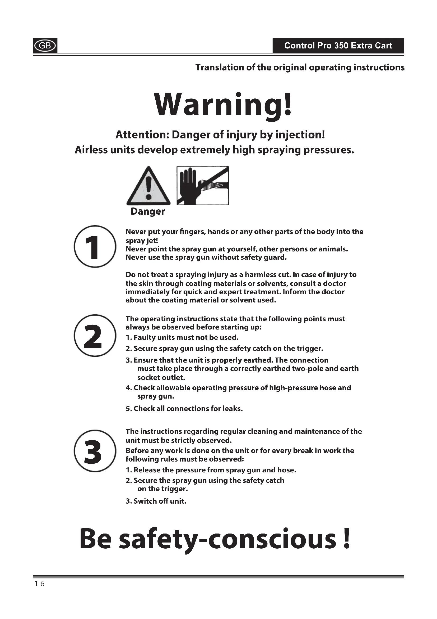
Attention: Danger of injury by injection! Airless units develop extremely high spraying pressures.

Danger

Never put your fingers, hands or any other parts of the body into the spray jet!
Never point the spray gun at yourself, other persons or animals. Never use the spray gun without safety guard.
Do not treat a spraying injury as a harmless cut. In case of injury to the skin through coating materials or solvents, consult a doctor immediately for quick and expert treatment. Inform the doctor about the coating material or solvent used.

The operating instructions state that the following points must always be observed before starting up:
- Faulty units must not be used.
- Secure spray gun using the safety catch on the trigger.
- Ensure that the unit is properly earthed. The connection must take place through a correctly earthed two-pole and earth socket outlet.
- Check allowable operating pressure of high-pressure hose and spray gun.
- Check all connections for leaks.

The instructions regarding regular cleaning and maintenance of the unit must be strictly observed.
Before any work is done on the unit or for every break in work the following rules must be observed:
- Release the pressure from spray gun and hose.
- Secure the spray gun using the safety catch on the trigger.
- Switch off unit.
Be safety-conscious!
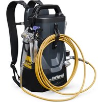
Congratulations on your purchase of a WAGNER colour application device.
You have purchased a proprietary device that requires careful cleaning and care to ensure trouble-free functioning. Read the operating instructions carefully before using the tool and observe the safety instructions. Keep the operating instructions in a safe place.
Explanation of symbols used
| Danger | Indicates an immediate danger. Unless avoided, death or serious injuries will result. |
| i | Indicates tips for use and other particularly useful information. |
| Wear suitable ear protection when working. | |
| Wear suitable respiratory equipment when working. | |
| Wear suitable safety gloves when working. |
General Safety Instructions
Warning!
Read all safety notifications and instructions. Failure to comply with the safety notifications and instructions provided may result in electric shock, fire and/or serious injury. Save all warnings and instructions for future reference. The term "power tool" used below covers both mains-operated power tools (with mains lead) and accumulator-operated power tools (without mains lead).
1. Safety at the workplace
a) Keep your workplace clean and well lit. Disorder or unlit workplaces may result in accidents.
b) Never use the tool in hazardous areas that contain flammable liquids, gases or dusts. Power tools generate sparks that can ignite the dust or vapors.
c) Keep children and other persons away when using the power tool. You can lose control of the tool if you are distracted.
2. Electrical Safety
a) The tool plug must fit into the socket. The plug may not be modified in any form. Do not use adaptor plugs together with protective-earthed tools. Unmodified plugs and suitable sockets reduce the risk of an electric shock.
b) Avoid physical contact with earthed surfaces such as pipes, heating elements, stoves and refrigerators. The risk through electric shock increases if your body is earthed.
c) Keep the equipment away from rain and moisture. The risk of an electric shock increases if water penetrates electrical equipment.
d) Do not misuse the mains lead by carrying the tool by the lead, hanging it from the lead or by pulling on the lead to remove the plug. Keep the lead away from heat, oil, sharp edges or moving tool parts. Damaged or twisted leads increase the risk of an electric shock.
e) If you work outdoors with a power tool, only use extension cables suitable for outdoor use. The use of an extension lead that is suitable for outdoors reduces the risk of an electric shock.
f) If you cannot avoid using the tool in a damp environment, use a residual current operated circuit-breaker. Using a residual current operated circuit-breaker avoids the risk of electric shock.
3. Safety of Persons
a) Be attentive. Pay attention to what you are doing and work sensibly with a power tool. Do not use the tool if you are tired or under the influence of drugs, alcohol or medication. Just a moment of inattention while using the tool can lead to serious injuries.
b) Wear personal safety equipment and always wear safety goggles. Wearing personal protective equipment, such as dust mask, non-slip safety shoes, safety helm or ear protection, depending on the type of power tools, reduces the risk of injury.
c) Avoid accidental starting-up. Ensure that the switch is in the "OFF" position before inserting the plug into the socket. Accidents can occur if you carry the power tool while your finger is on the switch or if you connect the power tool to the power supply which it is on.
d) Remove setting tools or wrenches before switching on the power tool. A tool or wrench that is in a rotating tool part can lead to injuries.
e) Avoid an unnatural posture. Ensure that you are standing securely and have your balance at all times. This ensures that you can control the tool better in unexpected situations.
f) Wear suitable clothing. Do not wear wide clothing or jewelry. Keep your hair, clothes and gloves away from moving parts. Loose clothing, jewelry or long hair can be caught in moving parts.
g) Do not lull yourself into a false sense of security and do not think yourself above the safety rules for electric tools, even if you are familiar with the electric tool following extensive practical experience. Careless use can lead to serious injuries in fractions of a second.
4. Careful Handling and Use of Power Tools
a) Do not overload the tool. Use the power tool designed for the work that you are doing. You work better and safer in the specified performance range if you use the suitable power tool.
b) Do not use power tools whose switch is defective. A power tool that cannot be switched on or off is dangerous and has to be repaired.
c) Remove the plug from the socket before carrying out tool settings, changing accessories or putting the tool away. This precautionary measure prevents unintentional starting of the tool.
d) Store unused power tools so that they are inaccessible to children. Do not let persons use the tool who are not familiar with it or who have not read these instructions. Power tools are dangerous when they are used by inexperienced persons.
e) Take proper care of your tools. Check whether the moving parts function trouble-free and do not jam, whether parts are broken or damaged so that the tool function is impaired. Have damaged parts repaired before using the tool. Many accidents have their origin in power tools that have been maintained badly.
f) Use the power tool, accessories, insert tools, etc. in accordance with these instructions and in a fashion specified for this special tool type. Take the working conditions and the activity to be carried out into consideration. The use of power tools for purposes other than the intended ones can lead to dangerous situations.
g) Keep the handles and grip surfaces dry, clean and free of oil and grease. Slippery handles and grip surfaces hamper safe operation and control of the electric tool in unforeseen situations.
5. Service
a) Have your tool repaired only by qualified specialist personnel and only with original spare parts. This ensures that the tool safety is maintained.
a) If the supply cord is damaged, it must be replaced by the manufacturer or it's service agent or a similarly qualified person in order to avoid a safety hazard.
Health protection

Caution! Wear breathing equipment: Paint mist and solvent vapors are damaging to health. Always wear breathing equipment and only work in well ventilated rooms or using supplementary ventilating equipment. It is advisable to wear working clothing, safety glasses, ear protection and gloves
Flammable materials

Do not use the spray guns to spray flammable substances.
Explosion protection

Do not use the unit in work places which are covered to the explosion protection regulations.
Danger of explosion and fire through sources of flame during spraying work

There may be no sources of flame such as, for example, open fires, smoking of cigarettes, cigars or tobacco pipes, sparks, glowing wires, hot surfaces, etc. in the vicinity.
Electrostatic charging (formation of sparks or flame)

Under certain circumstances, electrostatic charging can occur on the unit due to the rate of flow of the coating material when spraying. On discharging this can result in the emergence of sparks or fire. It is therefore necessary that the unit is always earthed through the electrical installation. The connection must take place through a correctly earthed two-pole-and-earth socket outlet.
Ventilation
Good natural or artificial ventilation must be ensured in order to avoid the risk of explosion or fire and damage to health during spray work.
Secure device and spray gun
All hoses, fittings, and filter parts must be secured before operating spray pump. Unsecured parts can eject at great force or leak a high pressure fluid stream causing severe injury.
Always secure the spray gun when mounting or dismounting the nozzle and in case of interruption to work.
Recoil of spray gun

In case of high operating pressure, pulling the trigger can effect a recoil force of up to 15 N. If you are not prepared for this, your hand can be thrust backwards or your balance lost. This can lead to injury. Continuous stress from this recoil can cause permanent damage to health.
Max. operating pressure
Max. permissible operating pressure for spray gun, spray gun accessories and high-pressure hose may not fall short of the maximum operating pressure of 110 bar (11 MPa) stated on the unit.
Coating substance
Caution against dangers that can arise from the sprayed substance and observe the text and information on the containers or the specifications given by the substance manufacturer.
Do not spray any liquid of unknown hazard potential.
High-pressure hose (safety note)

Attention, danger of injury by injection! Wear and tear and kinks as well as usage that is not appropriate to the purpose of the device can cause leakages to form in the high-pressure hose. Liquid can be injected into the skin through a leakage.
High-pressure hoses must be checked thoroughly before they are used.
Replace any damaged high-pressure hose immediately.
Never repair defective high-pressure hoses yourself!
Avoid sharp bends and folds: the smallest bending radius is about 20cm
Do not drive over the high-pressure hose. Protect against sharp objects and edges.
Never pull on the high-pressure hose to move the device.
Do not twist the high-pressure hose.
Do not put the high-pressure hose into solvents. Use only a wet cloth to wipe down the outside of the hose.
Lay the high-pressure hose in such a way as to ensure that it cannot be tripped over.
Electrostatic charging of spray guns and the high-pressure hose is discharged through the high-pressure hose. For this reason the electric resistance between the connections of the high-pressure hose must be equal or lower than 197kΩ /m (60 kΩ/ft.).

For reasons of function, safety and durability, only use genuine WAGNER high-pressure hoses and spray nozzles. For overview see "Spare parts lists".

The risk of damage rises with the age of the high-pressure hose. Wagner recommends replacing high-pressure hoses after 6 years.
Connecting the device
A properly earthed socket outlet with earthing contact must be used for connection. The connection must be equipped with a residual current protective device with INF ≤ 30 mA.
Setting up the unit

When working indoors:
Vapors containing solvents may not be allowed to build up in the area of the device.
Setting up the unit on the side a way from the sprayed object.
A minimum distance of 5m between the unit and spray gun is to be maintained.
When working outdoors:
Vapors containing solvents may not be allowed to blow toward the unit.
Note the direction of the wind.
Set the unit up in such a way that vapors containing solvents do not reach the unit and build up there.
A minimum distance of 5m between the unit and spray gun is to be maintained.
Maintenance and repairs

Before carrying out any work on the device, relieve the pressure and unplug the power plug from the socket.
Cleaning the unit

Danger of short circuit through penetrating water!
Never spray down the unit with high-pressure or high-pressure steam cleaners.
Cleaning units with solvents

When cleaning the unit with solvents, the solvent should never be sprayed or pumped back into a container with a small opening (bunghole). An explosive gas/air mixture can be produced. The container must be earthed.
Do not use flammable materials for cleaning purposes.
Earthing of the object
The object to be coated must be earthed.
Thermal release
The device is equipped with a thermal release which disconnects the device in case of overheating. In this case switch the device off, turn the selector switch to the PRIME position (vertical), remove the mains plug and allow device to cool down for min. 30
minutes. Eliminate the cause of heating, e.g. slots for air intake covered.
| Description (Fig. 1) | |
| 1 Hose holder 2 Inlet valve pusher | |
| 3 Telescopic handle 4 Integrated toolbox for nozzles and small parts | |
| 5 Pressure regulator with integrated ON/OFF switch 6 Hose connection | |
| 7 Selector switch 8 Holder for paint container | |
| 9 Pressure gauge 10 Suction hose | |
| 11 Return hose 12 Inlet filter | |
| 13 Operating instructions 14 High-pressure hose | |
| 15 Gun extension (30 cm) 16 Spray Gun | |
| 17 Nozzle 515 (for thick materials, e.g. interior wall paints) 18 Nozzle holder | |
| 19 HEA Filter Set 20 Gun filter: red (1 pc.), white (1 pc.* ) | |
| 21 Nozzle 311 (for thin materials, e.g. lacquers) 22 Nozzle 619 (for thick materials, e.g. interior wall paints. For coating larger surfaces) | |
- pre-installed in the filter housing
Coating Materials Suitable for Use
Dispersion and latex paints for interior use.
Water-based and solvent-containing lacquers and glazes. Paints, oils, release agents, synthetic enamels, PVC lacquers, undercoats, base coats, fillers and anti-rust paints.

Another nozzle size and gun filter must be used, depending on the material to be processed.
Thin materials: Nozzle 311
→ Filter red
Thick materials: Nozzle 515/619
→ Filter white
Coating Materials Not Suitable for Use
Materials that contain highly abrasive components, facade paint, caustic solutions and acidic coating substances.
Flammable materials, materials containing acetone or cellulose thinner

In order to ensure compatibility of the coating substance with the materials used to manufacture the device, please contact Wagner Service in cases of doubt.
Field of application
Coating interior walls and outside objects (e.g. garden fences, garage doors, etc.).
Required tools and auxiliary material
Wrench (13, 16, 17, 20) and/or adjustable wrench (2 pcs.) and hex key (10 mm)
- Hex key (2.5 mm)
- Empty container
A large piece of cardboard
- Covering material
Preparation of the workplace

Sockets and plugs must be masked. Risk of an electric shock as a consequence of sprayed material entering the socket!

Mask all the areas and objects that are not to be spray painted, or remove them from the work area.
No liability is assumed for damage due to overspray.
Silicate paint corrodes glass and ceramic surfaces upon contact! All such surfaces must therefore be completely covered.

Pay attention to the quality of the adhesive tape used. Do not use excessively strong adhesive tape on wallpaper and painted surfaces, in order to avoid damaging these surfaces when removing the tape. Remove adhesive tape slowly and evenly; do not use jerky movements. Do not leave adhesive tape on surfaces any longer than necessary, in order to minimise the possibility of residues when removing. Also observe the adhesive tape manufacturer's instructions.
Preparation of the Coating Material
Using Control Pro 350 Extra interior wall paints, varnishes and glazes can be applied by spraying without diluting them, or by diluting them slightly. Detailed information is available in the technical data sheet of the manufacturer (→ Internet download).
- Stir the material thoroughly and dilute it in the container as per the recommended dilution (an agitator is recommended for stirring).
| Thinning recommendation | |
| Sprayed material | |
| Glazes undiluted | |
| Wood preservatives containing solvents or based on water, mordants, oils, disinfection agents, plant protective agents | undiluted |
| Paints containing solvents and watersoluble paints, primers, vehicle coating paints, thick-film glazes | dilute by 5 - 10 % |
| Interior wall paint (dispersions and latex paint) dilute by 0-10 % | |

The values in the table are reference values.
Find out how much the paint needs to be thinned by testing it. Details on how to test the spray paint can be found in the section called "Spray Technique".
Assembly
- Place both doors / flaps in the storage compartment.
- Remove the protective covers on the hose and hose connection. (Fig. 2)
- Place the spray gun against the tapered end of the hose (Fig. 3, 1) and twist the gun onto the hose. Firmly tighten the thread using a wrench (13).

To check whether or not the hose is pressurized, the provided pressure gauge has to be secured to the high-pressure hose.
- Screw the pressure gauge to the hose connection.
- Screw the high pressure hose onto the pressure gauge. Using a wrench (16), hold the hose connection firmly and tighten the hose with another wrench (17). (Fig. 4)
- Slide the suction hose onto the inlet valve. Secure with the clamp. (Fig. 5)
- Press the return hose onto the return hose fitting. Secure with the clamp. (Fig. 6)
Control elements on the device (Fig. 7)
A The pressure of the spray is set by the pressure regulator.
The correct spray pressure depends on the paint being used.
The device is switched off if the pressure regulator is in position 0.
B The following settings can be made with the selector switch:
PRIME (Switch set vertically)

-Forprefilling the system with paint
For pressure relief
SPRAY (Switch set horizontally)

-For using the spray gun
Telescopic handle (Fig. 8)
The telescopic handle can be extended or retracted.
- To extend the handle: Pull out the handle from the cart frame until it snaps into place.
To retract the handle: Push the snap buttons on the back of the frame and push the handle back into the frame.
Spray Gun

Always lock the trigger off when attaching the spray nozzle or when the spray gun is not in use.
-
Fold the trigger lock downwards to lock the trigger (Fig. 9, A).
-
Fold the trigger lock upwards to unlock the trigger (Fig. 9, B).

Another nozzle size and gun filter must be used, depending on the material to be processed.
Thin materials: Nozzle 311

Filter red
Thick materials: Nozzle 515/619

Filter white
Pressure Relief Procedure

Be sure to follow the Pressure Relief Procedure when shutting the unit off for any purpose. This procedure relieves the pressure from the spray hose and the gun. Watch the pressure gauge --> 0 bar
- Secure the spray gun. (Fig. 9, A)
- Switch the device off (pressure regulator in position 0). Turn the switch into the PRIME position (vertical). (Fig.
- Release the spray gun. Hold the spray gun over an empty container and press the trigger to relieve the pressure.
- Secure the spray gun.
Start-up
Before connecting to the mains supply, be sure that the supply voltage is identical with the value given on the rating plate.
- Attach the return pipe to the suction hose using the clamps.
- Lower the suction hose into the paint container. (Fig. 11)
- Press the red inlet valve pusher to ensure that the inlet valve is free. (Fig. 12)
- Plug in the power cable.
- Turn the switch into the PRIME position (vertical).
- Switch the device ON by turning the pressure regulator slowly into position 2.
- Switch the device off again (pressure regulator 0) as soon as the paint flows through the return pipe and into the paint container.

If no paint is sucked in, try to solve the problem with the steps described in the following chapter "Help with suction problems".
- Turn the switch to the SPRAY position (horizontal).
- Hold the spray gun at the edge of an empty container. (Fig. 13)
- Release the spray gun and hold the trigger until the material emerges evenly.
- Let go of the trigger and secure the spray gun.
- Place the nozzle holder on the spray gun (Fig. 14, A) and rotate it into the final position (Fig. 14, B), in order to fix it.
- Insert the nozzle with the tip facing forward. (Fig. 15)
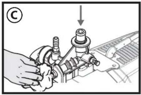
Help with suction problems
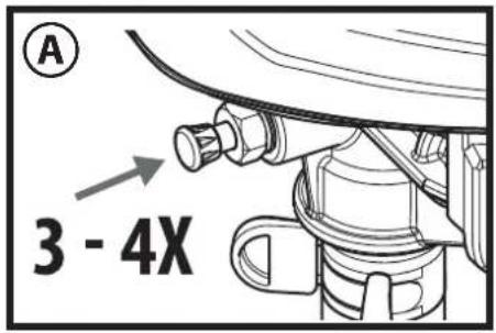
- Press the inlet valve pusher 3-4 times. (Fig. A) If the problem is not resolved, please continue with the following step.
- Lightly tap the hose connection several times with e.g. a rubber hammer. (Fig. B) If the problem is not resolved, please continue with the following step.
- Switch the device off (pressure regulator in position 0).
- Remove the suction hose and high pressure hose and turn the unit upside down.
- Fill approx. 10ml of water into the material inlet. (Fig.C)
- Press the inlet valve pusher 3-4 times.
- Hold a cloth in front of the hose connection and switch on the pump until water emerges from the hose connection.

If the problem is not resolved, please contact Customer Service

Spray Technique

Be sure to follow the Pressure Relief Procedure when shutting the unit off for any purpose. This procedure relieves the pressure from the spray hose and the gun. Watch the pressure gauge --> 0 bar
Be sure that the paint hose is free of kinks and clear of objects with sharp cutting edges.
It is best to practise on cardboard or a similar surface first of all, in order to check the spray pattern and become accustomed to using the spray gun.

If the paint sprays evenly, as shown in fig. 16 A, all the setting must be correct. If the paint looks stripy after spraying, as shown in fig. 16 B, gradually increase the pressure, or dilute more in 5% steps (please note the maximum amount of thinner stipulated by manufacturer.)
The key to obtaining a high quality result is even coating of the entire surface.
Keep your arm moving at a constant speed and keep the spray gun at a constant distance from the surface. The best spraying distance is approx. 20 to 25cm between the spray nozzle and the surface. (Fig. 17, A)
- Keep the spray gun at right angles to the surface. This means moving your entire arm back and forth rather than just flexing your wrist. (Fig. 17, B)
- Keep the spray gun perpendicular to the surface, otherwise one end of the pattern will be thicker than the other. (Fig. 17, C)
- Trigger gun after starting the stroke. Release the trigger before ending the stroke. (Fig. 17, D) The spray gun should be moving when the trigger is pulled and released. Overlap each stroke by about 30% . This will ensure an even coating.

During operation the pump switches on and off continuously, in order to regulate the pressure. This is normal and is not a malfunction.
Unclogging the Spray nozzle
If the spray pattern becomes distorted or stops completely while the gun is triggered, follow these steps.

Do not attempt to unclog or clean the nozzle with your finger. High pressure fluid can cause injection injury.
- Release the trigger and secure the gun. Rotate the reversible nozzle arrow 180° so that the point of the arrow is toward the rear of the gun. (Fig. 18).

Under pressure, the nozzle may be very difficult to turn. Turn the switch to the PRIME position (vertical) and pull the
trigger. This will relieve pressure and the tip will turn more easily.
- Turn the switch to the SPRAY position (horizontal).
- Unlock the gun and squeeze the trigger, pointing the gun at a scrap piece of wood or cardboard. This allows pressure in the spray hose to blow out the obstruction. When the nozzle is clean, material will come out in a straight, high pressure stream.
- Release the trigger and secure the gun. Reverse the nozzle so the arrow points forward again. Unlock the gun and resume spraying.

The HEA Filter Set keeps nozzle blockages to a minimum (see "HEA Filter Set").
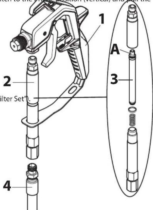
HEA Filter Set
Assembly

The gun and high-pressure hose must be de-pressurised before the filter set is installed / removed.
- Disconnect the high-pressure hose from the gun (1).
- If necessary, screw on the filter housing (2) and insert a filter (3) appropriate to the nozzle (the conical side (A) must point upwards).
Nozzle 311 → Filter red
Nozzle 517 / 619→ Filter white (pre-installed in the filter housing)
- Screw the filter housing (2) to the gun (1).
- Screw the high-pressure hose (4) firmly to the filter housing (2).
Cleaning

The gun and high-pressure hose must be de-pressurised before the filter set is installed / removed.
- Remove the filter housing (2) from the hose (4) and the gun (1).
- Screw on the filter housing (2) and remove the filter (3).
- Thoroughly clean the filter (3) and filter housing (2) (if worn, replace the filter).
- During reassembly, take care not to lose the seal and spring.
Interruption of Work

Be sure to follow the Pressure Relief Procedure when shutting the unit off for any purpose.
This procedure relieves the pressure from the spray hose and the gun.
Watch the pressure gauge --> 0 bar
- Switch the device off (pressure regulator in position 0) and remove the power plug.
- Put the spray gun in a plastic bag and seal so that it is air-tight.
- Wet paint surface in paint container with a little water to prevent a skin from forming.
Taking Out of Operation and Cleaning
Proper cleaning is the prerequisite for problem-free operation of the paint application device. No warranty claims are accepted in case of improper or no cleaning.

Do not use flammable materials / cellulose thinner for cleaning purposes.

Always clean the device as soon as you have finished operation. Dried-on coating substance makes cleaning more difficult.
- Perform Pressure Relief Procedure.
- Secure the spray gun.
- Remove the nozzle holder from the spray gun. (Fig. 19)
- Put the suction hose and return flow pipe into a container full of water or suitable cleaning solution.
- Turn the switch to the SPRAY position and set maximum pressure.
- Hold the spray gun on the edge of the paint container. (Fig. 20)

Ground gun with a metal container if flushing with solvent.
- Unlock the spray gun and pull the trigger to pump the excess paint out of the system into the paint container. Release the trigger again as soon as the cleaning agent comes out.
- Turn the switch into the PRIME position (vertical).
- Hold the spray gun on the edge of the cleaning container.
- Pull the trigger and hold it until only clear liquid comes out.
- Switch the device off and remove the power plug.
- Turn the switch into the PRIME position (vertical).
- Pull the trigger to relieve the pressure.
- Secure the spray gun.
- Separate the spray gun from the paint hose using wrenches (13).

If the HEA filter set is being used, remove it and clean it in accordance with the information in the chapter entitled "HEA Filter Set".
- Remove the nozzle (1), plain washer (2) and the mounting (3) from the nozzle holder (4) and clean all parts thoroughly. (Fig.21)
- Replace the mounting and the plain washer in the nozzle holder. Screw the nozzle holder onto the gun.
- Detach the suction hose from the basic unit.
- Disconnect the return line.
- Wipe off the exteriors of both hoses.
- Carefully remove the filter disc (1) from the suction filter. (Fig. 22)
- Clean the filter disk thoroughly under running water.
- Remove the high pressure hose from the basic unit with a wrench (17).
- Immerse the inlet valve in a container filled with conservation agent (e.g. household oil). (Fig. 23)
- Insert the power plug.
- Hold a cloth in front of the hose connection and switch the device on for approx. 5 seconds. (Fig. 24) This procedure preserves the pump.
Maintenance and repairs

Before carrying out any work on the device, relieve the pressure and unplug the power plug from the socket.
a) Cleaning the inlet valve

If any problems occur when the paint is sucked up, the intake valve needs to be cleaned or replaced. Problems can be avoided by cleaning and servicing the device properly.
- Detach the suction hose from the basic unit.
- Remove the inlet valve (Fig. 25, 1) from the base unit using a wrench (20 or Allen wrench 10mm ).
- Remove the valve seat (Fig. 25, 2), ball (3) and O-ring (4) from the inlet valve.
- Clean the inlet valve mount and all components thoroughly with a suitable cleaning solution or replace them if necessary.
- Lubricate the O-ring (Fig. 25, 5) on the inlet valve.
- Place the valve seat, ball and O-ring back in the inlet valve.
- Replace inlet valve assembly by screwing it into the sprayer.
b) Cleaning the outlet valve

If the spray pattern is poor, the outlet valve may need to be cleaned or replaced. Problems can be avoided by cleaning and servicing the device properly.
- Remove the high-pressure hose from the base unit using a wrench (17).
- Loosen the screw (Allen wrench 2.5mm ) on the outlet valve (Fig. 26), but do not remove it.
- Remove the outlet valve (Fig. 27, 1) from the base unit using a wrench (16).
- Clean the outlet valve mount and the outlet valve thoroughly with a suitable cleaning solution or replace the outlet valve if necessary.
- Put the new or cleaned outlet valve back in.
- Re-tighten the screw (Fig. 26).
Spare Parts List (Fig. 28)
| Pos. Description Order No. | ||
| 1 Spray gun assembly (incl. nozzle holder) 0517101 | ||
| 2 Nozzle holder 0517200 | ||
| 3 Sealing set 0517900 | ||
| 4 High pressure hose, 15 m 0517802 | ||
| 5 HEA Filter Set (incl. filter red and filter white) 0517202 | ||
| 6 Pressure gauge 0580402A | ||
| 7 Door (1 pc.) 0580041Y | ||
| 8 Telescope copic handle 0580390 | ||
| 9 Suction hose and Return line | 0580206A | |
| 10 | Clip (suction hose) | 9890222 |
| 11 | Clip (return line) | 0327226 |
| 12 | Return line | 0580208 |
| 13 | Clip (1 pc.) | 0512390 |
| 14 | Filter housing | 0580154 |
| 15 | Filter | 0580155 |
| 16 | Outlet valve | 0580072A |
| 17 | Repair kit for inlet valve | 0580391 |
| 18 | Inlet valve housing | 0580071A |
Accessories (not included in the delivery)
| Description | Order No. |
| Nozzle 211 (20° spray angle, 0.011 inch nozzle diameter) | 0517211 |
| Nozzle 311 (30° spray angle, 0.011 inch nozzle diameter) | 0517311 |
| Nozzle 313 (30° spray angle, 0.013 inch nozzle diameter) | 0517313 |
| Nozzle 413 (40° spray angle, 0.013 inch nozzle diameter) | 0517413 |
| Nozzle 515 (50° spray angle, 0.015 inch nozzle diameter) | 0517515 |
| Nozzle 517 (50° spray angle, 0.017 inch nozzle diameter) | 0517517 |
| Nozzle 619 (60° spray angle, 0.019 inch nozzle diameter) | 0517619 |
| Filter, red (nozzle 211/311/313/413, 1 pack) | 34383 |
| Filter, red (nozzle 211/311/313/413, 10 pack) | 97022 |
| Filter, yellow (nozzle 515, 1 pack) | 43235 |
| Filter, yellow (nozzle 515, 10 pack) | 97023 |
| Filter, white (nozzle 517/619, 1 pack) | 34377 |
| Filter, white (nozzle 517/619, 10 pack) | 97024 |
| Gun extension (30 cm) | 0517700 |
| Gun extension (60 cm) | 0517701 |
| Easy Glide (118 ml) | 0508619 |
Further information about the WAGNER range of products for renovating is available under www.wagner-group.com
| Technical Data | |
| Pump type Piston pump | |
| Power source 230 V | ~50 Hz/240 V~50 Hz |
| Power consumption | 600 W |
| Fusing Only connect to sockets protected with an FI fuse (16 A) | |
| Protection class I | |
| Max. spray pressure 11 MPa (110 bar) | |
| Max. delivery rate | 1.5 l/min |
| Sound pressure level * | 83 dB (A) Uncertainty K=3 db |
| Sound pressure output * | 97 dB (A) Uncertainty K=3 db |
| Oscillation level *<2.5 m/s | \( ^2 \) Uncertainty K=1.5 m/s2 |
| Max. temperature of coating substance 40°C | |
| Hose length 15 m | |
| Max. hose length | 30 m |
| Product dimensions approx. 78 (93.5) x 38.5 | x 52 cm |
| Weight approx. 13.0 kg | |
- Measured in accordance with EN 50580:2014
Information about the oscillation level
The specified oscillation level has been measured according to a standard test procedure and can be used to compare against electric tools. The oscillation level is also for determining an initial assessment of the vibrational strain.
Attention! The vibration emission value can differ from the specified value when the electric tool is actually in use, depending on how the electric tool is being used. It is necessary to specify safety measures to protect the operating personnel. These measures are based on an estimated shutdown during the actual conditions of use (all parts of the operating cycle are taken into consideration here, for example periods when the electric tool is switched off, and, when it is switched on but running without any load).
Environmental protection

The device and all accessories and packaging have to be re-used in an environmentally friendly manner. Do not dispose of the appliance with household waste. Support environmental protection by taking the appliance to a local collection point or obtain information from a specialist retailer.
Leftover paint and solvents may not be emptied into drains, the sewage system or disposed of as household rubbish. It has to be disposed of separately as special waste. Please pay special attention to the instructions on the product packaging.
Important Note regarding Product Liability!
Due to an EC ordinance in effect since 01.01.1990, the manufacturer is liable for his product only if all parts originate from or were approved by the manufacturer and the devices are assembled and operated correctly. The use of other accessories and spare parts can partially or completely invalidate the liability.
Correction of Malfunctions
| Problem Cause | Remedy | |
| The sprayer does not start. | •The sprayer is not plugged in. •The sprayer was turned off while still under pressure. •No voltage is coming from the wall plug. •The extension cord is damaged or has too low a capacity. •Device overheated •There is a problem with the motor. | →Plug the sprayer in. →Perform pressure relief procedure and set selector switch back to SPRAY →Properly test the power supply voltage. →Replace the extension cord. →Switch the device off, turn the selector switch to the PRIME position (vertical), remove the mains plug and allow device to cool down for min. 30 minutes. Eliminate the cause of overheating, e.g. covered ventilation slot. →Please contact Wagner Service |
| Problem Cause Remedy | ||
| The spray device runs but does not suck up any paint when the selector switch is set to the PRIME position. | ·The unit will not prime properly or has lost prime. ·The paint bucket is empty or the suction tube is not totally immersed in the paint. ·The suction tube is clogged. ·The suction tube is loose at the inlet valve. ·The inlet valve or outlet valve is stuck. ·The inlet valve is worn or damaged. ·The PRIME/SPRAY valve is plugged | →Try to prime the unit again. →Refill the bucket or immerse the suction tube in paint. →Clean the suction tube. →Tighten it securely. →Follow the instructions in the chapter "Help with suction problems". →Replace →Please contact Wagner Service |
| The sprayer draws up paint but the pressure drops when the gun is triggered. | ·The spray nozzle is worn. ·The inlet filter is clogged. ·The spray nozzle is blocked (if fitted) ·The paint is too viscous or contaminated. ·The inlet valve is worn or damaged. | →Replace the spray nozzle with a new nozzle. →Clean the inlet filter. →Clean or replace the filter. →Thin or strain the paint. →Replace |
| The spray gun leaks | ·Internal parts of the gun are worn or dirty. | →Please contact Wagner Service |
| The nozzle assembly leaks | ·The nozzle was assembled incorrectly. ·A seal is dirty. | →Check the tip assembly and assemble properly →Clean the seal. |
| The spray gun will not spray. | ·The spray nozzle is plugged. ·The spray nozzle is blocked (if fitted) ·The spray tip is in the reverse position. | →Clean the spray nozzle and use the HEA filter set. →Clean or replace the filter. →Put the nozzle in the forward position. |
| The paint pattern is tailing. | ·The paint is too viscous or contaminated. ·The spray nozzle is plugged. ·The spray nozzle is worn. ·The spray nozzle is blocked (if fitted) ·The inlet filter is clogged. ·The inlet valve is worn or damaged. | →Thin or strain the paint. →Clean the spray nozzle and use the HEA filter set. →Replace the spray nozzle with a new nozzle. →Clean or replace the filter. →Clean the inlet filter. →Replace |
Warning
If the supply cord of this appliance is damaged, it must only be replaced by a repair shop appointed by the manufacturer, because special purpose tools are required.
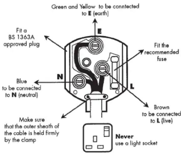
The wires in this mains lead are coloured in accordance with the following code:
green/yellow = earth blue neutral brown live
As the colours of the wires in the mains lead of this appliance may not correspond with the coloured markings identifying the terminals in your plug, proceed as follows:
- The wire which is coloured green and yellow must be connected to the terminal in the plug which is marked with the letter E or by the earth symbol or coloured green or green and yellow.
- The wire which is coloured blue must be connected to the terminal which is marked with the letter N or coloured black.
The wire which is coloured brown must be connected to the terminal which is marked with the letter L or coloured brown. - Should the moulded plug have to be replaced, never re-use the defective plug or attempt to plug it into a different 13 A socket. This could result in an electric shock.
- Should it be necessary to exchange the fuse in the plug only use fuses approved by ASTA in accordance with BS 1362. Only 13 Amp fuses may be used.
To ensure that the fuse and fuse carrier are correctly mounted please observe the provided markings or colour coding in the plug. - After changing the fuse, always make sure that the fuse carrier is correctly inserted. With out the fuse carrier, it is not permissible to use the plug.
- The correct fuses and fuse carriers are available from your local electrical supplies stockist.
3+1 years guarantee
The guarantee period amounts to 36 months in case of private use. In the case of private use, the guarantee is extended by a further 12 months if the device is registered online within 4 weeks of the purchase at www.wagner-group.com/3plus1. Registration is only possible if the buyer is in agreement with the data being stored that is entered during registration.
The guarantee period amounts to 12 months in case of commercial use. If the amount of paint processed with the unit exceeds 1,000 litres, this is considered to be commercial use.
We give a works guarantee to the following extent for this unit:
All those parts that prove to be unserviceable or to be considerably impaired in their serviceability within the guarantee period since the point of handing over to the buyer due to a circumstance lying before this handing over – in particular due to faulty design, bad building materials or poor execution – are improved or supplied new as we choose without costs.
Guarantee claims cannot be considered:
- for parts that are subject to wear and tear due to use or other natural wear and tear, as well as defects in the product that are a result of natural wear and tear, or wear and tear due to use. This includes in particular cables, valves, packaging, jets, cylinders, pistons, means-carrying housing components, filters, pipes, seals, etc. Damage due to wear and tear that is caused in particular by sanded coating materials, such as dispersions, glazes, quartz foundation.
- in the event of errors in devices that are due to non-compliance with the operating instructions, unsuitable or unprofessional use, incorrect assembly and/or commissioning by the buyer or by a third party, or utilisation other than is intended, abnormal ambient conditions, unsuitable coating materials, unsuitable operating conditions, operation with the incorrect mains voltage supply/ frequency, over-operation or defective servicing or care and/or cleaning.
- for errors in the device that have been caused by using accessory parts, additional components or spare parts that are not original Wagner parts.
- for products to which modifications or additions have been carried out.
- for products where the serial number has been removed or is illegible.
- for products where the serial number has been removed or is illegible
- for products with slight deviations from the target properties, which are negligible with regard to the value and usability of the device.
The unit is not conceived for use in shift work or for lending or leasing - these uses are excluded from the guarantee.
The replacement of a part does not extend the guarantee period of the unit.
The unit has to be examined immediately after receipt. Obvious faults are to be reported in writing within 14 days after receipt of the unit in order to avoid loss of the rights arising from faults.
We reserve the right to have the guarantee fulfilled by a contractual company.
Repairs going above and beyond those dealt with in these operating instructions are reserved for our factory. In case of a guarantee case or repair, please contact the specialist dealer from whom you purchased the unit.
Fulfilling of the guarantee depends on proof being provided by invoice and delivery note or proof of purchase.
If the check shows that the case is not a guarantee case, repairs are carried out at the expense of the buyer.
claims against Wagner that are based on or caused by the failure or insufficiency of a unit cannot be asserted.
We make it clear that the guarantee declaration does not represent a limitation of the statutory rights or of the rights agreed contractually through our general terms of business.
The above guarantees apply exclusively to products that have been bought by authorised specialist shops in the EU, CIS, Australia and are used within the reference country. If the check shows that the case is not a guarantee case, repairs are carried out at the expense of the buyer. The above regulations manage the legal relationship to us conclusively. Additional claims, in particular for damages and losses of any type, which occur as a result of the product or its use, are excluded from the product liability act except with regard to the area of application. Claims for liability for defects to the specialist trader remain unaffected. German law applies to this guarantee. The contractual language is German. In the event that the meaning of the German and a foreign text of this guarantee deviate from one another, the meaning of the German text has priority.
CE Declaration of Conformity
We declare under sole responsibility that this product conforms to the following relevant stipulations:
2006/42/EC, 2014/30/EU, 2011/65/EU, 2012/19/EU
Applied harmonised norms:
EN ISO 12100, EN 1953, EN 62841-1, EN 55014-1, EN 55014-2, EN 61000-3-2, EN 61000-3-3, EN 62233
The EU declaration of conformity is enclosed with the product.
If required, it can be re-ordered using order number 2374079.
GB Wagner Spraytech (UK) Limited
The Coach House
2 Main Road
Middleton Cheney OX17 2ND
Great Britain
UK-Helpline 01295 714200
Fax 01295710100
enquiries@wagnerspraytech.co.uk
B WSB Finishing Equipment
Veilinglaan 56-58
1861 Meise-Wolvertem
Belgium
Tel. +32/2/269 46 75
Telefax +32/2/269 7845
info@wagner-wsb.nl
E Makimport Herramentas, S.L.
C/Mejico n°6
NL WSB Finishing Equipment BV
De Heldinnenlaan 200,
3543 MB Utrecht
Netherlands
Tel. +31/ 30/241 41 55
Telefax +31/ 30/241 17 87
info@wagner-wsb.nl
D J.Wagner GmbH
Telefax 04.42.53.44.36
Not responsible for errors and changes.
Copyright by J.Wagner GmbH


- WARNING
- BE SAFETY-CONSCIOUS
- CONGRATULATIONS ON YOUR PURCHASE OF A WAGNER COLOUR APPLICATION DEVICE
- GENERAL SAFETY INSTRUCTIONS
- SAFETY AT THE WORKPLACE
- ELECTRICAL SAFETY
- SAFETY OF PERSONS
- CAREFUL HANDLING AND USE OF POWER TOOLS
- SERVICE
- HEALTH PROTECTION
- FLAMMABLE MATERIALS
- EXPLOSION PROTECTION
- DANGER OF EXPLOSION AND FIRE THROUGH SOURCES OF FLAME DURING SPRAYING WORK
- ELECTROSTATIC CHARGING (FORMATION OF SPARKS OR FLAME)
- VENTILATION
- SECURE DEVICE AND SPRAY GUN
- RECOIL OF SPRAY GUN
- MAX. OPERATING PRESSURE
- COATING SUBSTANCE
- HIGH-PRESSURE HOSE (SAFETY NOTE)
- CONNECTING THE DEVICE
- SETTING UP THE UNIT
- MAINTENANCE AND REPAIRS
- CLEANING THE UNIT
- CLEANING UNITS WITH SOLVENTS
- EARTHING OF THE OBJECT
- THERMAL RELEASE
- COATING MATERIALS SUITABLE FOR USE
- COATING MATERIALS NOT SUITABLE FOR USE
- FIELD OF APPLICATION
- REQUIRED TOOLS AND AUXILIARY MATERIAL
- PREPARATION OF THE WORKPLACE
- PREPARATION OF THE COATING MATERIAL
- ASSEMBLY
- CONTROL ELEMENTS ON THE DEVICE (FIG. 7)
- TELESCOPIC HANDLE (FIG. 8)
- SPRAY GUN
- PRESSURE RELIEF PROCEDURE
- START-UP
- HELP WITH SUCTION PROBLEMS
- SPRAY TECHNIQUE
- UNCLOGGING THE SPRAY NOZZLE
- HEA FILTER SET
- CLEANING
- INTERRUPTION OF WORK
- TAKING OUT OF OPERATION AND CLEANING
- GROUND GUN WITH A METAL CONTAINER IF FLUSHING WITH SOLVENT
- BEFORE CARRYING OUT ANY WORK ON THE DEVICE, RELIEVE THE PRESSURE AND UNPLUG THE POWER PLUG FROM THE SOCKET
- CLEANING THE INLET VALVE
- CLEANING THE OUTLET VALVE
- INFORMATION ABOUT THE OSCILLATION LEVEL
- ENVIRONMENTAL PROTECTION
- IMPORTANT NOTE REGARDING PRODUCT LIABILITY
- CORRECTION OF MALFUNCTIONS
- 3+1 YEARS GUARANTEE
- CE DECLARATION OF CONFORMITY
Brand : WAGNER
Model : Control Pro 350 Extra
Category : Paint spray