
ASE 400 - Dehumidifier Aerial - Free user manual and instructions
Find the device manual for free ASE 400 Aerial in PDF.
| Product Type | Adsorption Dehumidifier |
| Brand | Aerial |
| Model | ASE 400 |
| Main Use | Air dehumidification in enclosed indoor spaces (cellars, garages, warehouses) |
| Operating Mode | Adsorption with metal silicate rotor |
| Additional Function | Ventilation only (without dehumidification) |
| Control Panel | Toggle switches: On/Off/External and Continuous Fan |
| External Control Connection | Yes (for optional external hygrostat) |
| Operating Hours Counter | Yes |
| Dry Air Outlet | Front, diameter DN 100 mm |
| Regeneration Air Outlet | Rear, diameter DN 80 mm |
| Process Air Inlet | With removable air filter |
| Power Supply | Check the nameplate (voltage and frequency) |
| Electrical Protection | Residual current circuit breaker recommended in damp environments |
| Storage Temperature | -10 °C to +40 °C |
| Maintenance | Clean or replace the air filter regularly |
| Optional Accessories | Air hoses, external hygrostat |
| Delivery Contents | Unit, instruction manual |
| Compliance Standards | CE (Machinery Directive 2006/42/EC and EMC Directive 2014/30/EU) |
Frequently Asked Questions - ASE 400 Aerial
User questions about ASE 400 Aerial
0 question about this device. Answer the ones you know or ask your own.
Ask a new question about this device
Download the instructions for your Dehumidifier in PDF format for free! Find your manual ASE 400 - Aerial and take your electronic device back in hand. On this page are published all the documents necessary for the use of your device. ASE 400 by Aerial.
USER MANUAL ASE 400 Aerial
Adsorptionstrockner/Adsorption-dehumidifier
Serie/Series
ASE 200
ASE 300
ASE 400
EN Operation Instructions 13
FI Käyttöohje 24
natural_image
Yellow electronic device with four circular cutouts and a black triangular outline labeled '1' (no text or symbols on the device itself)natural_image
Simple diagram of a rectangular panel with a diagonal line and label '1' (no text or symbols on the panel itself)1 Models 13
2 Product overview ASE 200/300 14
3 Overview of control panel ASE 200/300....14
4 Product overview ASE 400 15
5 Overview of control panel ASE 400....15
6 About these operating instructions.... 16
7 Product description.... 16
8 Safety.... 16
9 Unpacking 17
10 Transport and connection 17
11 Operation.... 19
12 Maintenance and care 20
13 Troubleshooting 21
14 Decommissioning, storage and disposal 22
15 EC Declaration of Conformity.... 23
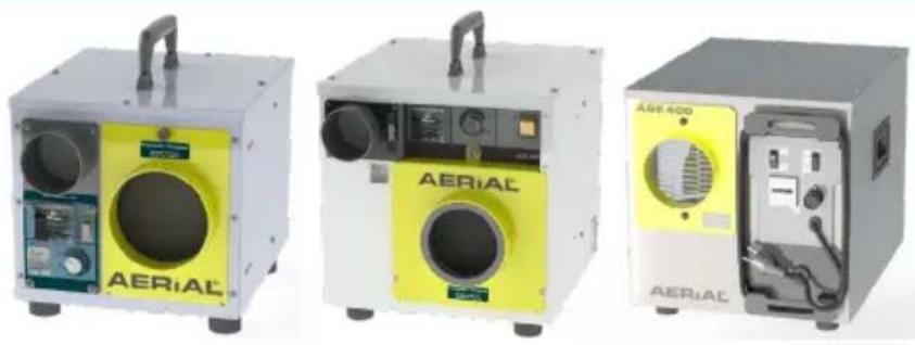
1 Models
These operating instructions relate to various models. The functions and operation are virtually identical. You can find out which model you have from the identification plate. Further information can be found in the Technical Data (see last page).
| Model | Main characteristics |
| ASE 200 | Humidity switch below the regeneration air outlet |
| ASE 300 | Humidity switch to the right of the regeneration air outlet |
| ASE 400 | No humidity switch |
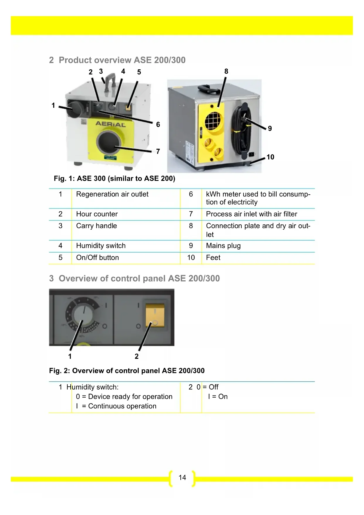
2 Product overview ASE 200/300
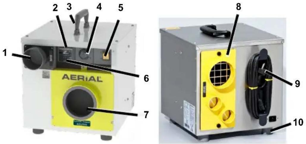
Fig. 1: ASE 300 (similar to ASE 200)
| 1 | Regeneration air outlet | 6 | kWh meter used to bill consumption of electricity |
| 2 | Hour counter | 7 | Process air inlet with air filter |
| 3 | Carry handle | 8 | Connection plate and dry air outlet |
| 4 | Humidity switch | 9 | Mains plug |
| 5 | On/Off button | 10 | Feet |
3 Overview of control panel ASE 200/300
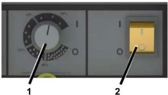
Fig. 2: Overview of control panel ASE 200/300
| 1 Humidity switch:0 = Device ready for operationI = Continuous operation | 2 0 = OffI = On |
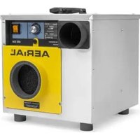
4 Product overview ASE 400
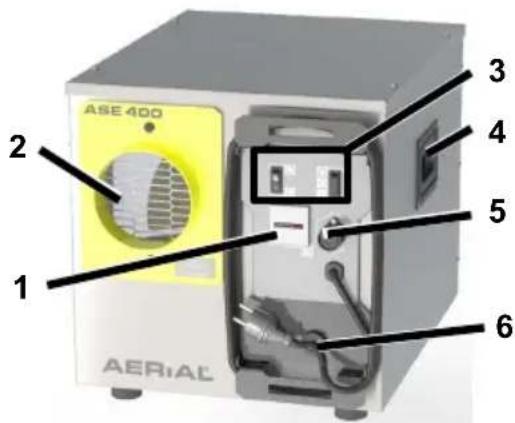
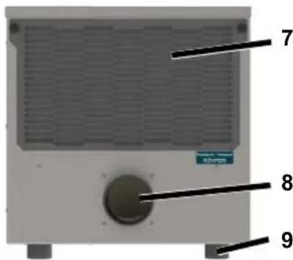
Fig. 3: ASE 400
| 1 Hour counter 6 Mains plug | |||
| 2 | Dry air outlet | 7 | Process air inlet with air filter |
| 3 | Control panel | 8 | Regeneration air outlet |
| 4 | Carry handle | 9 | Feet |
| 5 Connection for external control system | |||
5 Overview of control panel ASE 400
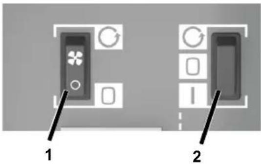
Fig. 4: Overview of control panel ASE 400
| 1 Continuous operation fan switch | 2 On/Off/External switch |
| = Fan operates continuously | = Continuous operation |
| = Fan only operates during dehumidification | = Off |
| = External control system (e.g. humidity switch) |
6 About these operating instructions
These operating instructions must not be reproduced, duplicated or distributed without the written consent of the-.
Important: Read carefully before use. Keep for later reference.
7 Product description
The adsorption-dehumidifier controls the air humidity in the room. The moist room air (also called ‘process air’) is drawn into the process air inlet and led through a turning rotor. The rotor features a metal silicate coating which serves to absorb the moisture from the process air.
The moisture absorbed by the rotor is driven out again by a heated air current, the so-called regeneration air.
A built-in, self-regulating heating element heats the regeneration air.
The moist, warm air current exits the unit at the regeneration outlet and must be directed out of the room by an exhaust hose or air duct.
The dry air is emitted into the room through the dry air outlet.
The ASE 400 can be used to dehumidify and ventilate or only to ventilate a room.
Package contents
• Adsorption-dehumidifier
- Operating instructions
Optional accessories
- Hoses
- External humidity switch for ASE 400
Identification plate
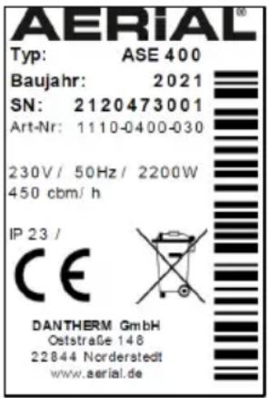
The identification plate is on the housing.
8 Safety
Intended use and conditions of use
The ASE series adsorption-dehumidifier is used to remove humidity from air where there is atmospheric pressure in closed indoor rooms, such as basements, garages or warehouses. The ASE 400 can also be used as a fan without dehumidifying.
The ASE 200/300 can be used in combination with a side channel blower or a noise box.
The adsorption-dehumidifier must only be used in compliance with the Technical Data (see last page).
During operation, the adsorption-dehumidifier creates negative pressure in the room, drawing in air, particles, smoke and gas from the outside or from adjacent rooms, which may present a hazard. The unit may only be operated in rooms in which it is easily possible to draw in air and in which no gas, smoke or similar and no objects such as paper may be drawn in and in which operation of the unit does not negatively impact chimneys, ovens or other equipment. Prior to using the adsorption-dehumidifier, take stock of these situations and
implement appropriate preventative measures such as switching off devices or sealing off dangerous rooms.
Persons with physical, sensory or mental restrictions and children are not permitted to use the adsorption-dehumidifier.
Every user must have read and understood the operating instructions.
Foreseeable misuse
The adsorption-dehumidifier must not be used:
- In environments in which particles, gas, smoke or similar could be drawn in by the negative pressure created, negatively impacting chimneys, ovens or other similar equipment.
- In rooms with potentially explosive atmospheres.
- In rooms with an aggressive atmosphere (e.g. caused by chemicals).
- In rooms with water with a pH value below 7.0 or above 7.4.
- In rooms with salt or liquids with a salt content > 1 %, e.g. brine baths.
- In moist areas of indoor swimming pools.
- In rooms with ozone-treated air, high solvent concentrations or high dust pollution.
General safety information
WARNING! Electrocution!
Working on live components or water on live components can cause life-threatening electrocution.
Avoid contact between water and live components.
Always switch off and unplug the adsorption-dehumidifier and drain away any water before moving it to another location.
- Only allow the manufacturer or authorised personnel to carry out work on electric components.
WARNING! Risk of burn!
- Only allow the manufacturer or authorised personnel to carry out work on internal components.
Do not reach into the regeneration air.
CAUTION! Cutting and crushing hazard!
Do not reach into the safety guard openings.
9 Unpacking
Procedure
- Check that the package contents are complete. Contact your stockist in the event of damage or missing contents.
- Remove the packaging and dispose of it in accordance with local regulations.
10 Transport and connection
Transport
WARNING! Crushing as a result of instability!
- Transport the adsorption-dehumidifier in an upright position and secure it so that it cannot tip over or slip.
Position the adsorption-dehumidifier on a stable, even surface.
When stored up high, secure the adsorption-dehumidifier so it cannot fall down.
WARNING! Crushing or cutting risk from reaching into the safety guard openings!
Use the handles to transport the adsorption-dehumidifier.
Do not reach into the safety guard openings.
CAUTION! Crushing or ergonomic damage when transporting the adsorption-dehumidifier!
- Use the handles to transport the adsorption-dehumidifier.
ASE 400 should always be transported by two people.
Procedure
- Make sure that the hoses (optional accessory) are removed from the regeneration air outlet and the dry air outlet and that the power cable is disconnected from the unit.
- Make sure that no particles or smoke, gas or similar may be drawn in and that the negative pressure created does not have a negative impact on safety or on the unit.
- Transport the adsorption-dehumidifier to the place of use.
ATTENTION! Damage to the device!
During operation, suction is created at the process air inlet. This suction may draw in paper or other light objects. When the process air inlet is covered, the unit may be damaged.
Make sure that no objects may be drawn in.
The air must circulate freely. Do not cover the air openings.
ASE 400: Connecting the external control system
If required, the ASE 400 may be controlled externally. The external control system must be suitable for at least 10 A.
Procedure
-
Connect the external control system to the port for the external control system.
-
Follow the operating instructions for the external control system.
Connecting the hoses/air ducts
In order to operate properly, a hose or air duct must be used to drive the regeneration air out of the room (e.g.
through a window). To do this, a suitable hose/air duct must be connected to the regeneration air outlet.
If required, a hose can be used to guide the dry air to the place of use. To do this, connect a suitable hose to the dry air outlet.
ATTENTION! Inadequate appliance output!
Do not bend the hose.
Do not place any objects on the hose.
Procedure for regeneration air
- Connect hose/air duct (DN 80 mm) to the regeneration air outlet and secure with a clamp, for example.
ASE 200/300: Regeneration air outlet on the front
ASE 400: Regeneration air outlet on the back.
- Lay the hose/air duct so the regeneration air is directed out of the room. Make sure that the hose slopes away from the adsorption-dehumidifier so that no condensate can get into the unit.
If it is not possible to create a slope, bend the hose/air duct down slightly. Drill a hole (D=4 mm) at the lowest point of the bend so the condensate can drain.
Procedure for dry air
- ASE 200/300 only: The dry air outlet is on the back. The connection plate can be turned, depending on the type of hose (ASE 200: 2 x DN 50 mm or 1 x DN 80 mm
ASE 300: 2 x DN 50 mm or 1 x DN
100 mm).
To do this, undo the screws (1) and align the desired opening so it is in front of the grille. Secure the connection plate using the screws.
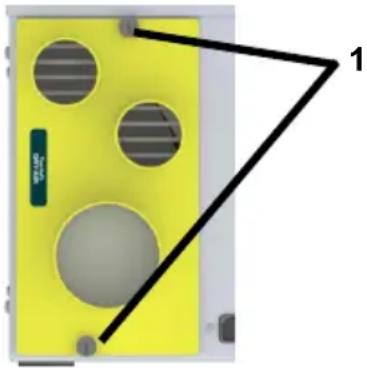
natural_image
Yellow electronic device with four circular cutouts and a black triangular outline labeled '1' (no text or symbols on the device itself)- If required, connect the hose to the dry air outlet and secure.
ASE 400: Dry air outlet on the front (DN 100 mm).
- Position the end of the hose at the place of use.
Electrical connection
Procedure
- Make sure that the supply voltage is the same as the connection voltage in the technical data.
- Provide an adequate fuse for the socket and the power supply.
- Install an earth leakage circuit breaker in damp rooms and building sites.
- Make sure that the mains plug is suitable for the socket of the building.
- Make sure that the socket used is earthed.
- Plug the mains plug into the socket.
11 Operation
WARNING! Negative effects caused by negative pressure.
Make sure that no particles or smoke, gas or similar may be drawn in.
Make sure that the negative pressure created has no negative effect on safety or on the unit.
CAUTION! Risk of burns due to hot regeneration air.
Do not reach into the regeneration air.
→ Make sure there is a hose/air duct attached to the regeneration air outlet.
ASE 200/300: Dehumidifying the room
ATTENTION! Damage to the device!
When using the device in combination with a side channel blower/noise box: Always put the humidity switch to the 'I' position.
NOTE: The ASE 200 must stand upright and may not be tilted, otherwise it does not function properly.
Procedure
- Make sure that the regeneration air is directed out of the room via a hose.
- Set on/off button to "I".
- Turn the humidity switch from "0" to "1". Set the desired humidity, e.g. 20%, at the humidity switch. The device will only start if the actual room humidity is higher than the target room humidity.
The dehumidifier will start operating. The adsorption-dehumidifier runs until the target room humidity has been reached, then it will stop running. If the humidity switch is at "I", the adsorption-dehumidifier will run continuously.
ASE 400: Ventilating the room
The procedure without an external control system is described below. If an external control system is connected, the ASE 400 can be set and operated using that system. To do this, set the On/Off/External switch to and follow the operating instructions for the control system.
Procedure
- Set the continuous operation fan switch to

The ASE 400 starts the fan in continuous operation without dehumidifying.
ASE 400: Dehumidifying the room
Procedure
- Make sure that the regeneration air is directed out of the room via a hose.
- Set the On/Off/External switch to
- Set the continuous operation fan switch to ☐
The dehumidifier will start operating. The adsorption-dehumidifier runs continuously.
Switching off
Procedure
-
Set the On/Off switch to '0' and the On/Off/External switch to ☐
-
ASE 400: Set the continuous operation fan switch to 🔒
12 Maintenance and care
WARNING! Damage to health from dust!
- Only clean the device with compressed air in open spaces.
- Wear a protective mask and goggles.
ATTENTION! Damage to property!
- Cleaning agents can damage surfaces. Only use mild detergents.
- Only use approved original spare parts.
Cleaning and inspection
Procedure
- Switch off Adsorption-dehumidifier.
- Unplug the mains plug.
- Remove the fastener (1) from the cover of the air filter.
ASE 200/300:
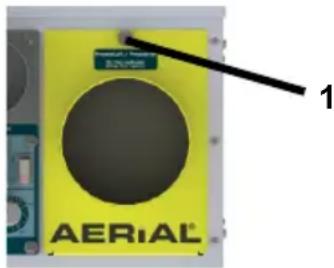
ASE 400:
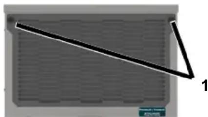
natural_image
Simple diagram of a rectangular panel with a diagonal line and label '1' (no text or symbols on the panel itself)- Remove the cover.
- Remove and clean the air filter (e.g. with vacuum cleaner) or replace it.
- Connecting the hoses/air ducts.
- Insert a new or clean filter. Only use an original filter.
- Put the cover back on and secure using the fastener (1).
- Plug in the mains cable.
- Switch on the adsorption-dehumidifier if necessary.
Spare parts and customer service
If you have any questions about the adsorption-dehumidifier or require spare parts, contact your authorised dealer or AERIAL Service.
13 Troubleshooting
Please check the following points in the event of a fault. If necessary contact AERIAL Service.
WARNING! Risk of burns, crushing and electrocution!
Only allow the manufacturer or authorised personnel to carry out repairs and maintenance work.
In the event of malfunctions, switch off the adsorption-dehumidifier and
secure it so that it cannot be switched back on again.
- Wait at least 15 seconds after switching it off so the rotor can stop turning.
Allow any hot components to cool sufficiently before working on them.
CAUTION! Mucous membrane irritation!
The rotor is coated with a metal silicate; these dust particles may irritate mucous membranes.
- Wear a protective mask and goggles.
Observe any information regarding safe handling while taking into consideration the safety data sheet and the operating instructions.
Faults
| Problem | Possible cause | Remedial action |
| The adsorption-dehumidifier is not performing well/removing moisture. | Air filter is dirty. The device is not getting enough air. Dirty filters can damage the appliance in the long term. | Clean the filter or replace if necessary. |
| The process air inlet is blocked. | Check process air inlet and remove any objects in front of it if necessary. | |
| The adsorption-dehumidifier is out of order/no fan noises are heard, no air current is perceptible at the dry air outlet or the regeneration air is the same temperature as the dry air. | The adsorption-dehumidifier is switched off. | Switch on the dehumidifier. |
| There is no power supply to the adsorption-dehumidifier. | Check the power supply. | |
| ASE 200/300: The desired room humidity has been reached. | Once the preset moisture has been exceeded, the adsorption-dehumidifier switches back on automatically. | |
| Appliance faulty. Contact the manufacturer. | Contact the manufacturer. |
14 Decommissioning, storage and disposal
Decommissioning
Procedure
- Switch off adsorption-dehumidifier.
- Unplug the mains plug.
- Cover the adsorption-dehumidifier with a cloth to protect it from dust.
Storage
CAUTION! Injury!
Do not stack more than two adsorption-dehumidifiers on top of each other.
- Secure the adsorption-dehumidifiers so that they do not fall over.
Procedure
- Store the adsorption-dehumidifier between -10 °C and +40 °C.
Disposal
ATTENTION! Risk from materials and substances
Sort materials according to type and recycle in accordance with local regulations.
- When disposing of auxiliary and operating materials, observe the local regulations and information on the safety data sheets.
Do not dispose of the adsorption-dehumidifier as household waste but rather in accordance with the legal regulations.
15 EC Declaration of Conformity
EC Declaration of Conformity in accordance with Machinery Directive 2006/42/EC Appendix II 1.A
Functional description: Adsorption-dehumidifiers are used to remove humidity from the air where there is atmospheric pressure in closed indoor rooms.
We hereby confirm that the product complies with the relevant provisions of the following directives:
• 2006/42/EC Machinery directive
• 2014/30/EU Directive on electromagnetic compatibility (EMC)
The following harmonised standards have been applied:
• EN 60335-2-40:2003
• EN 60335-1:2012
• EN 60204-1:2018
• EN ISO 12100:2010
• EN ISO 13857:2008
• EN ISO 14120:2015
Person authorised to compile the technical documentation: Manfred Föhlisch - Oststraße 148 - 22844 Norderstedt
Norderstedt, 07/12/2020
natural_image
Yellow electronic device with four circular cutouts and a black triangular outline labeled '1' (no text or symbols on the device itself)natural_image
Diagram of a gray rectangular panel with a diagonal line and label '1' pointing to one corner (no text or symbols on the panel itself)Fig. 4: Panoramica del pannello comandi ASE 400
natural_image
Yellow electronic device with four circular cutouts and a black triangular outline labeled '1' (no text or symbols on the device itself)natural_image
Simple diagram of a rectangular panel with a diagonal line and label '1' (no text or symbols on the panel itself)10 Transport et raccordement
Transport
natural_image
Yellow electronic device with four circular cutouts and a black triangular outline labeled '1' (no text or symbols on the device itself)natural_image
Diagram of a laptop with a diagonal line and label '1' pointing to the side panel (no text or symbols on the diagram itself)Fig. 4: Oversigt over betjeningspanel ASE 400
| 1 Kontakt ventilator permanent drift= ventilator permanent drift= ventilator kun tændt ved affugtning | 2 Kontakt til/fra/ekstern= permanent drift= fra= ekstern styring (f.eks. hygrostat) |
natural_image
Yellow electronic device with four circular cutouts and a black triangular outline labeled '1' (no text or symbols on the device itself)natural_image
Simple diagram of a rectangular panel with a diagonal line and label '1' (no text or symbols on the panel itself)FORSIGTIG! Fare for slimhindeirritation!
natural_image
Yellow electronic device with four circular cutouts and a black triangular outline labeled '1' (no text or symbols on the device itself)natural_image
Simple diagram of a triangular ruler placed on a grid surface, no text or symbols presentnatural_image
Yellow electronic device with four circular holes and a black triangular outline labeled '1' (no text or symbols on the device itself)natural_image
Simple diagram of a rectangular panel with a diagonal line and label '1' (no text or symbols on the panel itself)Fig. 4: Vista geral do painel de controlo ASE 400
natural_image
Yellow electronic device with four circular cutouts and a black triangular outline labeled '1' (no text or symbols on the device itself)natural_image
Pure geometric diagram showing a diagonal line and label '1' on a grid background (no text or symbols beyond labels)natural_image
Yellow electronic device with four circular cutouts and a black triangular outline labeled '1' (no text or symbols on the device itself)natural_image
Simple diagram of a rectangular panel with a diagonal line and label '1' (no text or symbols on the panel itself)natural_image
Yellow electronic device with four circular cutouts and a black triangular outline labeled '1' (no text or symbols on the device itself)natural_image
Diagram of a device with a diagonal line and label '1' pointing to a grid-patterned panel (no text or symbols on the diagram itself)WAARSCHUWING! Risico op ver- branding!
natural_image
Yellow electronic device with four circular cutouts and a black triangular outline labeled '1' (no text or symbols on the device itself)WAARSCHUWING! Gezondheids- schade door stof!
natural_image
Diagram of a rectangular panel with a diagonal line and label '1' (no text or symbols on the panel itself)WAARSCHUWING! Brandwonden, beknelling of stroomschok!
natural_image
Yellow electronic device with four circular holes and a black triangular outline labeled '1' (no text or symbols on the device itself)natural_image
Diagram of a rectangular panel with a diagonal line and label '1' (no text or symbols on the panel itself)

- Adsorptionstrockner/Adsorption-dehumidifier
- Serie/Series
- Models
- Product overview ASE 200/300
- Overview of control panel ASE 200/300
- Product overview ASE 400
- Overview of control panel ASE 400
- About these operating instructions
- Product description
- Package contents
- Optional accessories
- Identification plate
- Safety
- Intended use and conditions of use
- Foreseeable misuse
- General safety information
- WARNING! Electrocution!
- WARNING! Risk of burn!
- CAUTION! Cutting and crushing hazard!
- Unpacking
- Procedure
- Transport and connection
- Transport
- WARNING! Crushing as a result of instability!
- WARNING! Crushing or cutting risk from reaching into the safety guard openings!
- CAUTION! Crushing or ergonomic damage when transporting the adsorption-dehumidifier!
- ATTENTION! Damage to the device!
- ASE 400: Connecting the external control system
- Connecting the hoses/air ducts
- ATTENTION! Inadequate appliance output!
- Procedure for regeneration air
- Procedure for dry air
- Electrical connection
- Operation
- WARNING! Negative effects caused by negative pressure.
- CAUTION! Risk of burns due to hot regeneration air.
- ASE 200/300: Dehumidifying the room
- ASE 400: Ventilating the room
- ASE 400: Dehumidifying the room
- Switching off
- Maintenance and care
- WARNING! Damage to health from dust!
- ATTENTION! Damage to property!
- Cleaning and inspection
- Spare parts and customer service
- Troubleshooting
- WARNING! Risk of burns, crushing and electrocution!
- CAUTION! Mucous membrane irritation!
- Decommissioning, storage and disposal
- Decommissioning
- Storage
- CAUTION! Injury!
- Disposal
- ATTENTION! Risk from materials and substances
- EC Declaration of Conformity
- Transport et raccordement
- FORSIGTIG! Fare for slimhindeirritation!
- WAARSCHUWING! Risico op ver- branding!
- WAARSCHUWING! Gezondheids- schade door stof!
- WAARSCHUWING! Brandwonden, beknelling of stroomschok!
Brand : Aerial
Model : ASE 400
Category : Dehumidifier