DW096PK - Laser level DEWALT - Free user manual and instructions
Find the device manual for free DW096PK DEWALT in PDF.
User questions about DW096PK DEWALT
0 question about this device. Answer the ones you know or ask your own.
Ask a new question about this device
Download the instructions for your Laser level in PDF format for free! Find your manual DW096PK - DEWALT and take your electronic device back in hand. On this page are published all the documents necessary for the use of your device. DW096PK by DEWALT.
USER MANUAL DW096PK DEWALT
English (original instructions)
text_image
Technical diagram of a surveying instrument with numbered parts for identificationA

text_image
Technical diagram of a surveying instrument with labeled parts 10 and 11, showing structural components and alignment.B
text_image
28 19 13 12 15 14C
text_image
18 17 16D

text_image
21 20E

text_image
5 8
text_image
5 8F

text_image
23 22 24 242223 n 20 n X 100G1

text_image
26 25 27G2

text_image
29 8 29 5H

text_image
a b11
text_image
a' b'12
OPTISK NIVELLERINSTRUMENT DW096
Tillykke!
You have chosen a DEWALT product. Years of experience, thorough product development and innovation make DEWALT one of the most reliable partners for professional users.
Technical data
| Type | 1 | |
| Objective | mm | |
| Magnification 26 x | ||
| Accuracy (1 km double-run levelling) mm 2 | ||
| Viewing angle 1° 20' | ||
| Min. focus m 0.5 | ||
| Threaded pin | M16 x 11 | |
| Weight | kg 1.85 | |
Definitions: Safety Guidelines
The definitions below describe the level of severity for each signal word. Please read the manual and pay attention to these symbols.

DANGER: Indicates an imminently hazardous situation which, if not avoided, will result in death or serious injury.

WARNING: Indicates a potentially hazardous situation which, if not avoided, could result in death or serious injury.

CAUTION: Indicates a potentially hazardous situation which, if not avoided, may result in minor or moderate injury.
NOTICE: Indicates a practice not related to personal injury which, if not avoided, may result in property damage.

Denotes risk of electric shock.

Denotes risk of fire.

WARNING: To reduce the risk of injury, read the instruction manual.
Safety instructions for optical instruments
- Do not use the attachment for any purpose other than measuring heights, distances and angles.
- Do not look at strong light sources or the sun with optical instruments. DW096
- Do not use optical instruments to view laser beams.
- Avoid using the attachment while standing on potentially unstable objects such as scaffolding and stairs.
Markings on Tool
The following pictograms are shown on the tool:

Read instruction manual before use.
DATE CODE POSITION
The Date Code, which also includes the year of manufacture, is printed into the housing.
Example:
2010 XX XX
Year of Manufacture
Package contents
The package contains:
1 Optical level
1 Tripod
1 Grade rod
1 Kitbox
1 Plumb bob
1 Instruction manual
• Take the time to thoroughly read and understand this manual prior to operation.
Description (fi g. A)
Your DW096 optical level has been designed to aid in professional construction applications.
The attachment can be used both indoor and outdoor for levelling heights and for measuring angles and distances.
1 Eye piece
2 Optical peep sight
3 Focusing knob
4 Objective
5 Leveling screw
6 Flat head mount
7 Horizontal tangent drive
8 Air level
9 Prism
Assembly and adjustment
Mounting the attachment to the tripod (fi g. B)
The tripod has been equipped with a threaded pin to mount the attachment.
- Install the tripod on a relatively smooth and level surface.
- Mount the attachment to the tripod by turning the threaded pin (10) into the receptacle in the base of the attachment.
- Tighten the knob (11).

IG: Before mounting the attachment to the tripod, check that the legs are firmly set, that the tripod is wobble free and level.
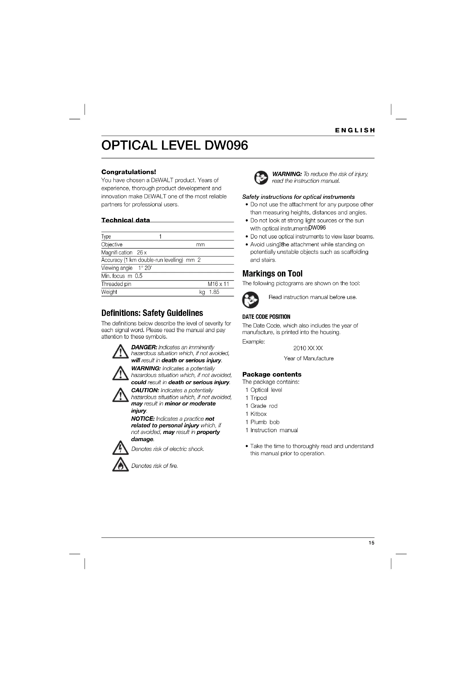
Installing the tripod (fi g. C & D)
- Release the plastic snap (12) at the end of the nylon strap holding the tripod legs together.
- Spread the legs (13) apart to install the tripod in upright position.
- Adjust the legs (13) if required so that each of the feet (14) is firmly touching the ground.
- Step on each of the brackets (15) to press the feet (14) into soft ground.
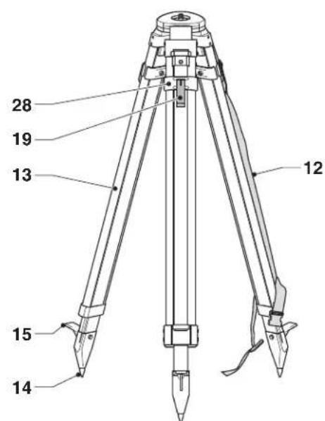
- Unwind as much cord of the plumb bob (16) as required.
- Hang the reel (17) onto the hook (18).
- Check whether the plumb bob dangles freely.
-
Wind the surplus of the cord onto the reel (17) if the plumb bob touches the ground.
-
Adjust the legs above the middle of the triangle of the base until the tripod is level as indicated by the plumb bob.
- Remove the plumb bob from the hook.
- Mount the attachment to the tripod.
Adjusting the leg height (fi g. C)
- Release the quick-adjust latch (19) of the first leg (13) to set the desired height. Re-tighten the latch.
- Repeat as for the other legs.
Extending the grade rod (fi g. E)
The grade rod consists of several telescoping sections. Each section is locked in place by a spring-loaded button to hold the grade rod at various lengths.
- To extend the grade rod (20) one section, slide the section out until the spring-loaded button (21) engages.
- To shorten the grade rod one section, press the button and slide the section back in.
Level adjustment (fi g. A & F)
For easy reference, the attachment must be positioned in such a way that the objective is above one of the levelling screws (5) as shown.
- Look straight into the prism (9). The air level (8) should be centred in the vial.
- If adjustment is required, proceed as follows:
- Turn the rear levelling screws (5) to bring the air level (8) to the edge of the vial as indicated.
- Centre the air level by turning the front levelling screw (5).
Focusing (fi g. A)
- Look over and through the optical peep sight (2) to point the objective (4) towards the object to be measured.
- Looking through the eyepiece, turn the eyepiece (1) until the hairlines in the reticle are sharp and clear.
- Turn the focusing knob (3) until the object to be measured is sharp and clear.
Angular adjustment
- Turn the horizontal tangent drive (7) as necessary.
OPERATION
Instructions for Use
WARNING: Always observe the safety instructions and applicable regulations.
Measuring (fi g. G1 & G2)
The attachment is equipped with a stadia reticle to make the measurements as described below.
Measuring heights
- Extend the grade rod (20) as far as it will go.
- Place the rod near the object to be measured.
- Point the attachment towards the grade rod.
- Read the height at the middle stadia line.
Measuring distances
- Extend the grade rod (20) as far as it will go.
- Place the rod near the object to be measured.
- Point the attachment towards the grade rod.
- Read the grade rod from the upper stadia line (23) and the lower stadia line (24).
- Subtract the reading of the lower stadia line from the reading of the upper stadia line.
- Multiply the outcome of the subtraction (n) by 100.
The result is the estimated distance between the rod and the centre of the attachment in centimetres.
Measuring angles
- Point the attachment towards the first object (25).
- Read the object at the vertical hair line (26).
- Align the 0^ position on the scale with the eyepiece.
- Rotate the attachment to point it towards the second object (27).
- Read the object at the vertical hair line.
- Read the angle ( ) from the scale.
Optional accessories
Consult your dealer for further information on the appropriate accessories.
MAINTENANCE
Your attachment has been designed to operate over a long period of time with a minimum of maintenance. Continuous satisfactory operation depends upon proper tool care and regular cleaning.
Re-adjusting the quick-adjust latch of the tripod (fi g. C)
- If the quick-adjust latch (19) is loose in the locked position, tighten the quick-adjust latch assembly nut (28).
Calibrating the air level (fi g. H)
When the attachment is adjusted to level position, the air level (8) should remain centred at any angle.
- Centre the air level using the levelling screws (5).
- Turn the attachment 180^
If the air level does not remain centred, proceed as follows:
- Turn the levelling screws (5) to bring the air level (8) halfway to the centre.
- Turn the adjustment screws (29) to centre the air level using the Hex wrench provided.
- Repeat this procedure until the air level remains centred when the attachment is rotated 180^ .
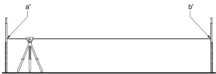
Field calibration check (fi g. I1 & I2)
The field calibration checks must be performed securely and accurately to make a correct diagnosis. Whenever an error is registered, have the attachment serviced by a qualified repair agent.
- Place the attachment in an area between two grade rods that are at least 50 m apart. Position the attachment so that it is aimed front-to-back towards the grade rods.
- Place the attachment exactly in between the grade rods.
- Point the attachment towards the first rod.
- Read the height at the middle stadia line (a). Register the reading.
- Rotate the attachment 180^ to point it towards the second rod.
- Read the height at the middle stadia line (b). Register the reading.
- Move the attachment in a straight line to the first rod. Place the attachment at 2 m from the rod.
- Point the attachment towards the first rod.
- Read the height at the middle stadia line (a'). Register the reading.
- Rotate the attachment 180^ to point it towards the second rod.
- Read the height at the middle stadia line (b'). Register the reading.
ENGLISH
- Calculate the following equation: b' = a' - (a - b) .
- If the equation is valid, the attachment is properly calibrated.
- If the equation is invalid, the attachment must be serviced.
Protecting the Environment
Separate collection. This product must not be disposed of with normal household waste.
Should you find one day that your DEWALT product needs replacement, or if it is of no further use to you, do not dispose of it with household waste. Make this product available for separate collection.

Separate collection of used products and packaging allows materials to be recycled and used again. Re-use of recycled materials helps prevent environmental pollution and reduces
the demand for raw materials.
Local regulations may provide for separate collection of electrical products from the household, at municipal waste sites or by the retailer when you purchase a new product.
DEWALT provides a facility for the collection and recycling of DEWALT products once they have reached the end of their working life. To take advantage of this service please return your product to any authorised repair agent who will collect them on our behalf.
You can check the location of your nearest authorised repair agent by contacting your local DEWALT office at the address indicated in this manual. Alternatively, a list of authorised DEWALT repair agents and full details of our after-sales service and contacts are available on the Internet at: www.2helpU.com.
GUARANTEE
DEWALT is confident of the quality of its products and offers an outstanding guarantee for professional users of the product. This guarantee statement is in addition to and in no way prejudices your contractual rights as a professional user or your statutory rights as a private non-professional user. The guarantee is valid within the territories of the Member States of the European Union and the European Free Trade Area.
• 30 DAY NO RISK SATISFACTION GUARANTEE •
If you are not completely satisfied with the performance of your DEWALT tool, simply return it within 30 days, complete with all original components, as purchased, to the point of purchase, for a full refund or exchange. The product must have been subject to fair wear and tear and proof of purchase must be produced.
• ONE YEAR FREE SERVICE CONTRACT •
If you need maintenance or service for your DEWALT tool, in the 12 months following purchase, you are entitled to one service free of charge. It will be undertaken free of charge at an authorised DEWALT repair agent. Proof of purchase must be produced. Includes labour. Excludes accessories and spare parts unless failed under warranty.
• ONE YEAR FULL WARRANTY •
If your DEWALT product becomes defective due to faulty materials or workmanship within 12 months from the date of purchase, DEWALT guarantees to replace all defective parts free of charge or – at our discretion – replace the unit free of charge provided that:
• The product has not been misused;
- The product has been subject to fair wear and tear;
• Repairs have not been attempted by unauthorised persons;
• Proof of purchase is produced.
- The product is returned complete with all original components
If you wish to make a claim, contact your seller or check the location of your nearest authorised DEWALT repair agent in the DEWALT catalogue or contact your DEWALT office at the address indicated in this manual. A list of authorised DEWALT repair agents and full details of our after-sales service is available on the Internet at: www.2helpU.com
NIVEL ÓPTICO DW096
¡Enhorabuena!
L'emballage contient: