
DW087 - Laser level DEWALT - Free user manual and instructions
Find the device manual for free DW087 DEWALT in PDF.
| Brand | DEWALT |
| Model | DW087 |
| Category | Laser level |
| Power supply | 3 LR6 (AA) batteries, 1.5 V each |
| Nominal voltage | 4.5 V |
| Battery type | Alkaline LR6 (AA) |
| Laser power | < 1.3 mW |
| Laser class | 2 (EN 60825-1:2007) |
| Wavelength | 637 nm (red) |
| Protection rating | IP54 (protected against dust and water splashes) |
| Self-leveling range | ± 4° |
| Working temperature | -10 °C to +45 °C |
| Weight | 0.75 kg |
| Receptacle thread | M6 x 20 |
| Projection | Horizontal and vertical laser lines (crosshair) |
| Self-leveling | Yes, ±4° range |
| Swivel mount | With built-in magnets for attachment to metal surfaces |
| Wall mount | Included, with clamping jaws and screw fixing |
| Package contents | Laser, wall mount, 3 batteries, carrying case, instruction manual |
| Cleaning | Soft cloth for the housing, cotton swab moistened with alcohol for the lens |
| Warranty | 30-day satisfaction, 1 year free maintenance, 1 year full warranty |
Frequently Asked Questions - DW087 DEWALT
User questions about DW087 DEWALT
0 question about this device. Answer the ones you know or ask your own.
Ask a new question about this device
Download the instructions for your Laser level in PDF format for free! Find your manual DW087 - DEWALT and take your electronic device back in hand. On this page are published all the documents necessary for the use of your device. DW087 by DEWALT.
USER MANUAL DW087 DEWALT
English (original instructions) 41
KLASSE 2 LASERPRODUKT
PRODUKT DER KLASSE 2
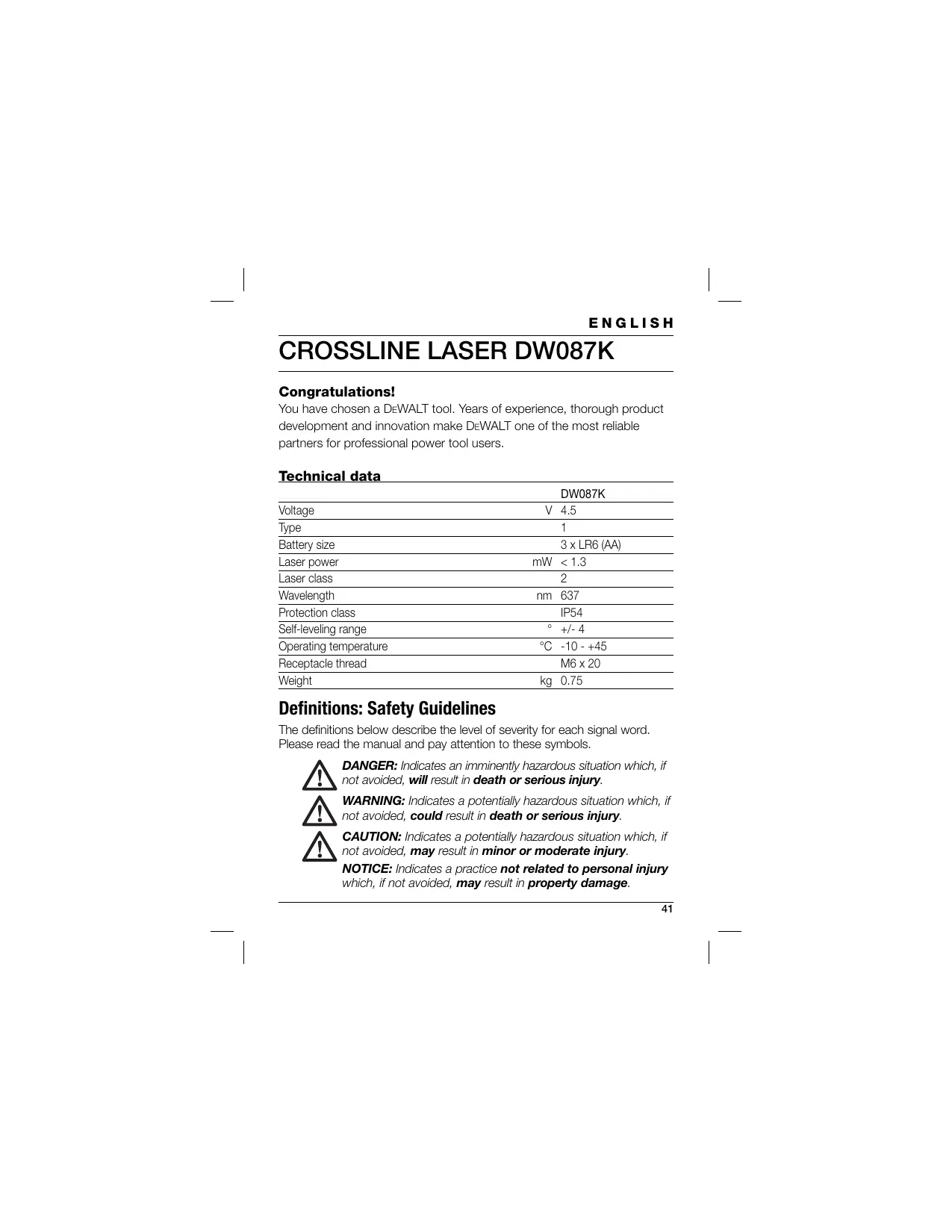
You have chosen a DeWALT tool. Years of experience, thorough product development and innovation make DeWALT one of the most reliable partners for professional power tool users.
Technical data
| DW087K | |
| Voltage | V 4.5 |
| Type | 1 |
| Battery size | 3 x LR6 (AA) |
| Laser power | mW < 1.3 |
| Laser class | 2 |
| Wavelength | nm 637 |
| Protection class | IP54 |
| Self-leveling range | ° +/- 4 |
| Operating temperature | °C -10 - +45 |
| Receptacle thread | M6 x 20 |
| Weight | kg 0.75 |
Definitions: Safety Guidelines
The definitions below describe the level of severity for each signal word. Please read the manual and pay attention to these symbols.

DANGER: Indicates an imminently hazardous situation which, if not avoided, will result in death or serious injury.

WARNING: Indicates a potentially hazardous situation which, if not avoided, could result in death or serious injury.

CAUTION: Indicates a potentially hazardous situation which, if not avoided, may result in minor or moderate injury.
NOTICE: Indicates a practice not related to personal injury which, if not avoided, may result in property damage.
ENGLISH

Denotes risk of electric shock.

Denotes risk of fire.
Safety Instructions for Lasers

WARNING! Read and understand all instructions. Failure to follow all instructions listed below may result in electric shock, fire and/or serious personal injury.
SAVE THESE INSTRUCTIONS
- Do not operate the laser in explosive atmospheres, such as in the presence of flammable liquids, gases or dust. Power tools create sparks which may ignite the dust or fumes.
- Use the laser only with the specifically designated batteries. Use of any other batteries may create a risk of fire.
- Store idle laser out of reach of children and other untrained persons. Lasers are dangerous in the hands of untrained users.
- Use only accessories that are recommended by the manufacturer for your model. Accessories that may be suitable for one laser, may create a risk of injury when used on another laser.
- Tool service MUST be performed only by qualified repair personnel. Repairs, service or maintenance performed by unqualified personnel may result in injury. For the location of your nearest authorized DeWALT repair agent, refer to the list of authorized DeWALT repair agents on back of this manual or visit www.2helpU.com on the Internet.
- Do not use optical tools such as a telescope or transit to view the laser beam. Serious eye injury could result.
- Do not place the laser in a position which may cause anyone to intentionally or unintentionally stare into the laser beam. Serious eye injury could result.
ENGLISH
- Do not position the laser near a reflective surface which may reflect the laser beam toward anyone's eyes. Serious eye injury could result.
- Turn the laser off when it is not in use. Leaving the laser on increases the risk of staring into the laser beam.
- Do not operate the laser around children or allow children to operate the laser. Serious eye injury may result.
- Do not remove or deface warning labels. If labels are removed user or others may inadvertently expose themselves to radiation.
- Position the laser securely on a level surface. Damage to the laser or serious injury could result if the laser falls.
- Dress properly. Do not wear loose clothing or jewelry. Contain long hair. Keep your hair, clothing, and gloves away from moving parts. Loose clothing, jewelry or long hair can be caught in moving parts. Air vents often cover moving parts and should also be avoided.

WARNING: Use of controls or adjustments or performance of procedures other than those specified herein may result in hazardous radiation exposure.

WARNING! DO NOT DISASSEMBLE THE ROTARY LASER. There are no user serviceable parts inside. Disassembling the rotary laser will void all warranties on the product. Do not modify the product in any way. Modifying the tool may result in hazardous laser radiation exposure.

WARNING: Fire hazard! Avoid short-circuiting the contacts of a removed battery.
Additional safety instructions for lasers
- This laser complies with class 2 according to EN 60825-1:2007. Do not replace a laser diode with a different type. If damaged, have the laser repaired by an authorised repair agent.
ENGLISH
- Do not use the laser for any purpose other than projecting laser lines. An exposure of the eye to the beam of a class 2 laser is considered safe for a maximum of 0.25 seconds. Eyelid reflexes will normally provide adequate protection. At distances over 1m , the laser complies with class
1 and thus is considered completely safe.
- Never look into the laser beam directly and intentionally.
- Do not use optical tools to view the laser beam.
- Do not set up the tool at a position where the laser beam can cross any person at head height.
- Do not let children come in contact with the laser.
Residual Risks
The following risks are inherent to the use of this device:
injuries caused by staring into laser beam.
Labels on tool
The following pictographs are shown on the tool:
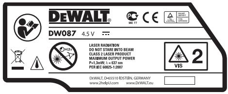

Read the instruction manual before use

Laser warning

Do not stare into the laser beam.

Protection class: IP54
DATE CODE POSITION
The Date Code, which also includes the year of manufacture, is printed on the inside of the battery compartment.
Example:
2010 XX XX
Year of Manufacture
Important Safety Instructions for Batteries

WARNING: Batteries can explode, or leak, and can cause injury or fire. To reduce this risk:
- Carefully follow all instructions and warnings on the battery label and package.
- Always insert batteries correctly with regard to polarity (+ and - ), marked on the battery and the equipment.
- Do not short battery terminals.
- Do not charge batteries.
- Do not mix old and new batteries. Replace all of them at the same time with new batteries of the same brand and type.
- Remove dead batteries immediately and dispose of per local codes.
- Do not dispose of batteries in fire.
- Keep batteries out of reach of children.
- Remove batteries if the device will not be used for several months.
Batteries (fig. B)
BATTERY TYPE
This laser operates on three LR6 (AA-size) batteries.
ENGLISH
INTENDED USE
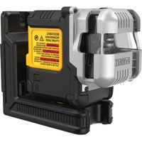
The crossline laser DW087K has been designed to project laser lines to aid in professional applications. The tool can be used indoor for horizontal (level), vertical (plumb) and square alignment. The applications range from layout of walls and windows to installation of framing track.
DO NOT use under wet conditions or in presence of flammable liquids or gases.
The crossline laser is a professional tool. DO NOT let children come into contact with the tool. Supervision is required when inexperienced operators use this tool.
Package contents
The package contains:
1 Crossline laser
1 Wall mount
3 Batteries
1 Kitbox
1 Instruction manual
- Take the time to thoroughly read and understand this manual prior to operation.
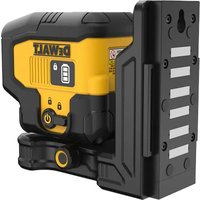
Description (fig. A)
1 On/off switch (vertical laser beam)
2 On/off switch (horizontal laser beam)
3 Low battery indicator
4 Vertical laser beam
5 Horizontal laser beam
6 Vertical laser beam indicator
7 Horizontal laser beam indicator
8 Pivot bracket
9 Wall mount
10 Battery compartment
Unpacking
FITTING THE WARNING LABEL
The safety warnings on the label shown on the laser must be formulated in the language of the user.
For that purpose, a separate sheet of self-adhesive labels has been supplied with the tool.

WARNING: Check that the safety warnings on the label have been formulated in your language.
The warnings should read as follows:
LASER RADIATION
DO NOT STARE INTO BEAM
CLASS 2R LASER PRODUCT
-
If the warnings are in a foreign language, proceed as follows:
-
Remove the required label from the sheet.
- Carefully place the label over the existing label.
- Press the label in place.
ASSEMBLY AND ADJUSTMENT

WARNING! Do not place the laser in a position which may cause anyone to intentionally or unintentionally stare into the laser beam. Serious eye injury may result from staring at the beam.
Replacing batteries (fig. A & B)
The attachment uses batteries of type LR6 (AA).
- Open the battery compartment cover (9).
- Replace the batteries (11). Make sure the new batteries are placed as indicated.
- Close the battery compartment cover.
ENGLISH
WARNING: When replacing batteries, always replace the complete set. Do not mix old batteries with new ones. Preferably use alkaline batteries.
Low battery indicator (fig. A)
The tool has been equipped with a low battery indicator (3) located on the control panel. The low battery indicator is lit while the tool is switched on. It will blink to indicate that the batteries need to be replaced and the tool will automatically shut down.
- Switch off the tool and remove the batteries as soon as the indicator blinks.
Setting up the tool (fig. C1 - C4)
The tool facilitates various set-ups, making it useful for several applications.
Floor set-up
- Place the tool on a relatively smooth and level surface.
Wall set-up (fig. C1)
The keyhole (12) in the pivot bracket (8) is used for mounting to wall constructions. Alternatively, the tool can be attached to metal studs directly using the magnets (13).
- Drive a screw or nail into the wall.
- Hang the tool onto the fastener by the keyhole.
Fitting the tool to the wall mount (fig. C2 - C4)
The tool has been equipped with a wall mount (9) for mounting to wall track to aid in drop ceiling installation and other specialty leveling projects. The pivot bracket (8) has magnets to attach the tool to the wall mount.
- Align the magnets (13) with the metal plate on the wall mount (9).
- To remove the wall mount, pull the wall mount from the tool applying sufficient force.
ENGLISH
To fit the wall mount to wall track, proceed as follows:
- Open the clamp jaws (14).
- Place the clamp jaw around the wall track and release the clamp to close the clamp jaws shut on the track.
To mount the wall mount to a wall, proceed as follows:
- Hold the tool at the desired position against the wall and mark the location of the mounting hole on the wall.
- Drill a hole at the marked location.
- Insert a corresponding plug into the hole.
- Hold the tool in front of the plug.
- Turn a screw into the mounting hole (15).
Adjusting the tool
- To initiate the leveling procedure, switch on the tool. The level and/or plumb orientation is correctly adjusted as long as the laser beams remain on.
- The laser beams start flashing to indicate that the tool has been set up at a slope that is beyond the self-leveling range of 4^ . Switch the tool off, re-adjust the tool set-up within the self-leveling range and switch the tool on again.
Aligning the laser line (fig. D)
- Align the laser line of either one of the laser beams with the position mark. Move the tool as required.
OPERATION

WARNING! Do not place the laser in a position which may cause anyone to intentionally or unintentionally stare into the laser beam. Serious eye injury may result from staring at the beam.
ENGLISH
Instructions for use

WARNING: Always observe the safety instructions and applicable regulations.
- Always mark the centre of the laser dots.
- Make sure the tool has been set up securely.
- Extreme temperature changes cause movement of internal parts that may affect the accuracy of the tool. Regularly check the accuracy while using the tool under these circumstances.
- Although the tool corrects small out-of-level errors automatically, when it is bumped, re-adjustment to balance or set-up may be required.
- If the tool has been dropped or has tipped over, check whether there is damage by performing the field calibration checks.
See "Maintenance".
Switching on and off (fig. A)
The tool has separate switches to operate the vertical laser line and the horizontal laser line.
- To switch the vertical laser beam (4) on, press the on/off switch (1).
- To switch the horizontal laser beam (5) on, press the on/off switch (2).
- To switch either laser beam off, press the on/off switch again.
Transferring a position mark (fig. D)
The tool produces two laser lines in horizontal and in vertical direction, to transfer a mark.
- Align the relevant laser beam with the mark.
Rotating the tool (fig. E)
When in wall set-up, the tool can be rotated manually to transfer the horizontal laser line.
- Rotate the tool to the left or right as required.
Optional accessories
Consult your dealer for further information on the appropriate accessories.
MAINTENANCE
Your DEWALT power tool has been designed to operate over a long period of time with a minimum of maintenance. Continuous satisfactory operation depends upon proper tool care and regular cleaning.
Field calibration check (fig. F-H)
The field calibration check must be performed securely and accurately to make a correct diagnosis. Whenever an error is registered, have the tool serviced by a qualified repair agent.

WARNING: The conditions of the area are indicative of the results presented. If the practice differs from these conditions, the measurements have to be adjusted accordingly.
Scan check (fig. F)
- Place the tool in an area between two vertical surfaces that are at least 9m apart. Mount the tool exactly midways to the wall.
- Position the tool at an angle of 45^ to the left.
- Switch on the horizontal laser beam.
- Mark the centre of the laser beam exactly midways on the opposite wall.
- Switch off the tool and rotate it 90^ clockwise.
- Switch on the horizontal laser beam.
- Mark the centre of the laser beam exactly midways on the opposite wall.
- Switch off the tool.
Measure the difference between the markings. - If the difference between the markings is 3mm or less, the tool is properly calibrated.
- If the difference between the markings is more than 3mm , the tool must be serviced.
ENGLISH
Level check (fig. G1 & G2)
- Place the tool in an area with a wall of at least 9 m length. Mount the tool to one end of the wall.
- Position the tool at an angle of 90^ to the left.
- Switch on the horizontal laser beam.
- Mark the centre of the laser beam at one-third distance (16) and at two-thirds distance (17) on the wall.
- Switch off the tool.
- Mount the tool to the other end of the wall.
- Position the tool at an angle of 90^ to the right.
- Switch on the horizontal laser beam.
- Switch on the tool, align the laser beam with the wall marking (17) and mark the laser beam at two-third distance (18) on the wall.
- Switch off the tool.
Measure the difference between the markings (16 & 18). - If the difference between the markings is 6mm or less, the tool is properly calibrated.
- If the difference between the markings is more than 6mm , the tool must be serviced.
Plumb check (fig. H1 & H2)
- Place the tool on the floor in an area with a ceiling of at least 2.5m height.
- Mark a line of 1.5m length (19) on the floor. Position the tool at one end of the floor marking (19).
- Switch on the vertical laser beam.
- Align the laser beam with the floor marking (19).
- Mark the centre of the laser beam at one-third distance (20) and at two-thirds distance (21) on the ceiling.
- Switch off the tool. Position the tool at the other end of the floor marking (19) facing the marking.
ENGLISH
- Switch on the vertical laser beam.
- Align the laser beam with the floor marking (19).
- Mark the centre of the laser beam at one-third distance (22) and at two-third distance (23) on the ceiling.
- Switch off the tool.
Measure the difference between the markings (20 & 22).
Measure the difference between the markings (21 & 23). - If the difference between the markings is 3.5 ~mm or less, the tool is properly calibrated.
- If the difference between the markings is more than 3.5mm , the tool must be serviced.

Cleaning
- Remove the batteries before cleaning the tool.
- Regularly clean the housing with a soft cloth.
- When necessary, clean the lens using a soft cloth or a cotton bud soaked in alcohol. Do not use any other cleaning agents.
Protecting the Environment

Separate collection. This product must not be disposed of with normal household waste.
Should you find one day that your DEWALT product needs replacement, or if it is of no further use to you, do not dispose of it with household waste. Make this product available for separate collection.

Separate collection of used products and packaging allows materials to be recycled and used again. Re-use of recycled materials helps prevent environmental pollution and reduces the demand for raw materials.
ENGLISH
Local regulations may provide for separate collection of electrical products from the household, at municipal waste sites or by the retailer when you purchase a new product.
DeWALT provides a facility for the collection and recycling of DeWALT products once they have reached the end of their working life. To take advantage of this service please return your product to any authorised repair agent who will collect them on our behalf.
You can check the location of your nearest authorised repair agent by contacting your local DeWALT office at the address indicated in this manual. Alternatively, a list of authorised DeWALT repair agents and full details of our after-sales service and contacts are available on the Internet at:
www.2helpU.com.

Batteries
- When disposing batteries, think of the protection of the environment. Check with your local authorities for an environmentally safe way of battery disposal.
GUARANTEE
DeWALT is confident of the quality of its products and offers an outstanding guarantee for professional users of the product. This guarantee statement is in addition to and in no way prejudices your contractual rights as a professional user or your statutory rights as a private non-professional user. The guarantee is valid within the territories of the Member States of the European Union and the European Free Trade Area.
30 DAY NO RISK SATISFACTION GUARANTEE
If you are not completely satisfied with the performance of your DeWALT tool, simply return it within 30 days, complete with all original components, as purchased, to the point of purchase, for a full refund or exchange. The product must have been subject to fair wear and tear and proof of purchase must be produced.
- ONE YEAR FREE SERVICE CONTRACT
If you need maintenance or service for your DeWALT tool, in the 12 months following purchase, you are entitled to one service free of charge. It will be undertaken free of charge at an authorised DeWALT repair agent. Proof of purchase must be produced. Includes labour. Excludes accessories and spare parts unless failed under warranty.
- ONE YEAR FULL WARRANTY
If your DeWALT product becomes defective due to faulty materials or workmanship within 12 months from the date of purchase, DeWALT guarantees to replace all defective parts free of charge or – at our discretion – replace the unit free of charge provided that:
The product has not been misused;
- The product has been subject to fair wear and tear;
- Repairs have not been attempted by unauthorised persons;
Proof of purchase is produced.
ENGLISH
- The product is returned complete with all original components
If you wish to make a claim, contact your seller or check the location of your nearest authorised DeWALT repair agent in the DeWALT catalogue or contact your DeWALT office at the address indicated in this manual. A list of authorised DeWALT repair agents and full details of our after-sales service is available on the Internet at: www.2helpU.com
FRANÇAIS
L'emballage contient:
Installation murale (fig. C1)
LASERPRODUKT AV KLASSE 2
TITTA INTE IN I STRÄLEN
LASERPRODUKT AV KCLASS 2
- Definitions: Safety Guidelines
- ENGLISH
- Safety Instructions for Lasers
- SAVE THESE INSTRUCTIONS
- Additional safety instructions for lasers
- Residual Risks
- Labels on tool
- DATE CODE POSITION
- Important Safety Instructions for Batteries
- Batteries (fig. B)
- BATTERY TYPE
- INTENDED USE
- Package contents
- Description (fig. A)
- Unpacking
- FITTING THE WARNING LABEL
- ASSEMBLY AND ADJUSTMENT
- Replacing batteries (fig. A & B)
- Low battery indicator (fig. A)
- Setting up the tool (fig. C1 - C4)
- Floor set-up
- Wall set-up (fig. C1)
- Fitting the tool to the wall mount (fig. C2 - C4)
- Adjusting the tool
- Aligning the laser line (fig. D)
- OPERATION
- Instructions for use
- Switching on and off (fig. A)
- Transferring a position mark (fig. D)
- Rotating the tool (fig. E)
- Optional accessories
- MAINTENANCE
- Field calibration check (fig. F-H)
- Scan check (fig. F)
- Level check (fig. G1 & G2)
- Plumb check (fig. H1 & H2)
- Cleaning
- Protecting the Environment
- Batteries
- GUARANTEE
- DAY NO RISK SATISFACTION GUARANTEE
- - ONE YEAR FREE SERVICE CONTRACT
- - ONE YEAR FULL WARRANTY
- FRANÇAIS
- Installation murale (fig. C1)
Brand : DEWALT
Model : DW087
Category : Laser level