DCLE14301G - Laser level DEWALT - Free user manual and instructions
Find the device manual for free DCLE14301G DEWALT in PDF.

User questions about DCLE14301G DEWALT
0 question about this device. Answer the ones you know or ask your own.
Ask a new question about this device
Download the instructions for your Laser level in PDF format for free! Find your manual DCLE14301G - DEWALT and take your electronic device back in hand. On this page are published all the documents necessary for the use of your device. DCLE14301G by DEWALT.
USER MANUAL DCLE14301G DEWALT
English (original instructions)
7
Francais (traduction de la notice d'instructions originale) 19
WARNING: Read all safety warnings and all
Inactions. Failure to follow the warnings and instructions may result in electric shock, fire and/or serious injury.

WARNING: To reduce the risk of injury, read the instruction manual.
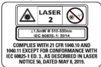
Laser Information
The DCLE14301G three plane laser is a Class 2 laser product. This product complies with 21 CFR 1040.10 and 1040.11 except for conformance with IEC 60825-1 Ed.3., as described in Laser Notice No.56, dated May 8, 2019.
Conforms to UL STDS 61010-1 & 2595
Certified to CSA STD C22.2 No. 61010-1
Supplier's Declaration of Conformity 47 CFR 2.1077 Compliance Information
Responsible Party - U.S. Contact Information
DEWALT
701 East Joppa Road
Towson, Maryland 21286
www.DEWAIT.com
FCC Compliance Statement
This equipment has been tested and found to comply with the limits for a Class B digital device, pursuant to Part 15 of the FCC Rules. These limits are designed to provide reasonable protection against harmful interference in a residential installation. This equipment generates, uses and can radiate radio frequency energy and, if not installed and used in accordance with the instructions, may cause harmful interference to radio communications. However, there is no guarantee that interference will not occur in a particular installation. If this equipment does cause harmful interference to radio and television reception, which can be determined by turning the equipment off and on, the user is encouraged to try to correct the interference by one or more of the following measures:
- Reorient or relocate the receiving antenna.
English
- Increase the separation between the equipment and receiver.
- Connect the equipment into an outlet on a circuit different from that to which the receiver is connected.
- Consult the dealer or an experienced radio/TV technician for help.
ISED Compliance Statement
This device contains license-exempt transmitter(s)/receiver(s) that comply with Innovation, Science, and Economic Development Canada's license-exempt RSS(s). Operation is subject to the following two conditions:
- This device may not cause interference.
- This device must accept any interference, including interference that may cause undesired operation of the device.
USER SAFETY
Safety Guidelines
The definitions below describe the level of severity for each signal word. Please read the manual and pay attention to these symbols.
DANGER: Indicates an imminently hazardous situation which, if not avoided, will result in death or serious injury.
WARNING: Indicates a potentially hazardous situation which, if not avoided, could result in death or serious injury.
CAUTION: Indicates a potentially hazardous situation when, if not avoided, may result in minor or moderate injury.
NOTICE: Indicates a practice not related to personal injury which, if not avoided, may result in property damage.
If you have any questions or comments about this or any DeWALT tool,
call 1-800-4-DEWAIT (1-800-433-9258)
or go to www.DEWAIT.com.
English
WARNING: Never modify the tool or any part of it. Damage to the laser or personal injury could result.
WARNING: Read and understand all instructions. Failure to follow the warnings and instructions may result in electric shock, fire and/or serious injury.
SAVE THESE INSTRUCTIONS
WARNING: Laser Radiation Exposure. Do not assemble or modify the laser level. There are no user serviceable parts inside. Serious eye injury could result.
WARNING: Hazardous Radiation. Use of controls or experiments or performance of procedures other than those specified herein may result in hazardous radiation exposure.
CAITION: Keep fingers clear of the back plate and when mounting with magnets. Fingers may become pinched.
CAITION: Do not stand underneath the laser when it is mounted with the magnet bracket. Serious personal injury or damage to the laser may result if the laser falls.
The label on your laser may include the following symbols.
| SymbolMeaning | |
| V Volts | |
| mW Milliwatts | |
| 4 | Laser Warning |
| nm Wavelength in nanometers | |
| 2 Class 2 Laser | |
Warning Labels (Fig. A)
For your convenience and safety, the following labels are on your laser level.


WARNING: To reduce the risk of injury, user must read instruction manual.
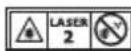
WARNING:LASER RADIATION. DO NOT STARE INTO BEAM.Class 2 Laser Product.


WARNING: Keep clear of magnet. Magnet hazard can disturb pacemaker operation and result in serious injury or death.
- If the equipment is used in a manner not specified by the manufacturer, the protection provided by the equipment may be impaired.
- Do not operate the laser level in explosive atmospheres, such as in the presence of flammable liquids, gases, or dust. This laser level may create sparks which may ignite the dust or fumes.
- Store an idle laser level out of reach of children and other untrained persons. Lasers are dangerous in the hands of untrained users.
- Tool service MUST be performed by qualified repair personnel. Service or maintenance performed by unqualified personnel may result in injury. To locate your nearest DEWALT service center go to www.DEWALT.com
- Do not use optical tools such as a telescope or transit to view the laser beam. Serious eye injury could result.
- Do not place the laser level in a position which may cause anyone to intentionally or unintentionally stare into the laser beam. Serious eye injury could result.
- Do not position the laser level near a reflective surface which may reflect the laser beam toward anyone's eyes. Serious eye injury could result.
- Turn the laser level off when it is not in use. Leaving the laser level on increases the risk of staring into the laser beam.
- Do not modify the laser level in any way. Modifying the laser level may result in hazardous laser radiation exposure.
ENGLISH
- Do not operate the laser level around children or allow children to operate the laser level. Serious eye injury may result.
- Do not remove or deface warning labels. If labels are removed, the user or others may inadvertently expose themselves to radiation.
- Position the laser level securely on a level surface. If the laser level falls, damage to the laser level or serious injury could result.
Personal Safety
- Stay alert, watch what you are doing, and use common sense when operating the laser level. Do not use the laser level when you are tired or under the influence of drugs, alcohol, or medication. A moment of inattention while operating the laser level may result in serious personal injury.
- Use personal protective equipment. Always wear eye protection. Depending on the work conditions, wearing protective equipment such as a dust mask, non-skid safety shoes, hard hat, and hearing protection will reduce personal injury.
Laser Level Use and Care
- Do not use the laser level if the pendulum lock/unlock and power switch do not turn the laser level on or off. Any laser level that cannot be controlled with the switch is dangerous and must be repaired.
- Follow instructions in the Maintenance section of this manual. Use of unauthorized parts or failure to follow Maintenance instructions may create a risk of electric shock or injury.
Important Safety Instructions for All Integral Battery Charging
WARNING: Read all safety warnings, instructions, cautionary markings for the battery, USB cable and product. Failure to follow the warnings
and instructions may result in electric shock, fire and/or serious injury.
WARNING: Use the recommended power adapter P5E-D1C0AVU (5-20V, <=3.0A). If your laser level was not sold with this charger, use a certified power adapter that is compliant with applicable country regulations and international/regional safety standards with an output of 5-20V, 3A. The power adapter MUST be a Class 2 power supply. Using adapters that do not meet applicable safety standards could result in injury.
- Charge this laser every month if not in constant use, and after each use when used often to ensure battery longevity.
- The provided USB cable is not intended for any uses other than charging DEWALT rechargeable tools with USB ports. Charging other types of tools may cause their batteries to overheat and burst, resulting in personal injury, property damage, fire, electric shock or electrocution.
DO NOT expose USB cable to water, rain or snow. - Pull by the plugs rather than the cord when disconnecting the USB cable. This will reduce the risk of damage to the plugs and cord.
- Make sure that the cord is located so that it will not be stepped on, tripped over or otherwise subjected to damage or stress.
- DO NOT use a USB cable with a damaged cord or plugs. Have them replaced immediately.
- Foreign materials of a conductive nature, such as, but not limited to, grinding dust, metal chips, steel wool, aluminum foil or any buildup of metallic particles should be kept away from the USB plugs and port.
- Always unplug the USB cable from the power supply when there is no tool attached to it.
Charging Procedure (Fig. A, B)
WARNING: The power adapter MUST be a Class 2 power supply.
ENGLISH
- Pull the USB charging port cover 17 away from the laser level.
- Insert the USB cable 15 into the charging port 4.
- Plug the USB cable 15 into power supply 16.
- Plug the power supply into a wall outlet.
- Charging is complete when all three bars of the battery meter 9 light up on the side of the laser level. The battery can be left charging or the USB cable can be disconnected.
Important Charging Notes
- The laser level may become warm to the touch while charging. This is a normal condition, and does not indicate a problem. To facilitate the cooling of the laser level after use, avoid placing the laser level in a warm environment such as in a metal shed or an uninsulated trailer.
- If the laser level does not charge properly, take the laser level and USB cable to your local service center.
- You may charge a partially used battery whenever you desire with no adverse effect on the laser level
NOTE: The laser level may be used while charging.
Hot and Cold Condition
On charging, when the temperature is 125^ (52^) or higher (hot condition) or 32^ (0^) or colder (cold condition), the charging is turned off and the following battery state of charge pattern will flash:
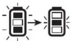
Until the temperature is between 122^ (50^) and 32^ (0^) , the charging will not turn on and the indication shown above will continue.
Viewing the Battery Meter (Fig. A, C)
When the laser level is ON, the state of battery meter 9 on
the keypad indicates how much power remains.
- All three LEDs will flash when the battery level is low (< 10%). The laser level may continue to operate for a short time while the battery power continues to drain.
- After the battery is charged, and the laser level is turned ON again, the battery indicator level will indicate full capacity.
- If any or all of the LEDs on the battery meter remain ON, this indicates that the laser level is not fully powered OFF. When the laser level is not in use, make sure the pendulum lock/unlock and power switch 12 is placed to the DOWN Locked/OFF position.
| BATTERY METER LED | STATE OF CHARGE |
| Battery is 80%-100% charged | |
| Battery is 50%-80% charged | |
| Battery is 10%-50% charged | |
| Battery is < 10% charged | |
| Battery is < 10% charged, unit is charging |
OPERATING TIPS
- To extend battery life per charge, turn the laser level off when it is not in use.
- Lowering the brightness of laser level increases battery life.
To ensure the accuracy of your work, check the laser level calibration often. Refer to Checking Laser Accuracy. - Before attempting to use the laser level, make sure it is positioned securely, on a smooth, flat stable surface that is level in both directions.
CAUTION: To reduce the risk of serious injury, stare directly into the laser beam with or without glasses.
Always mark the center of the beam created by the laser level.
- Extreme temperature changes can cause movement or shifting of building structures, metal tripods, equipment, etc., which can affect accuracy. Check your accuracy often while working.
- If the laser level has been dropped, check to make sure your laser level is still calibrated. Refer to Checking Laser Accuracy.
Turning the Laser On (Fig. A, C)
Your laser level is equipped with a three-position pendulum lock/unlock and power switch 12.
Horizontal position: Power off
- Middle position: Manual Slope Mode (Power On, Pendulum Locked)
Vertical position: Self-Leveling Mode (Power On, Pendulum Unlocked)
The laser beams will turn on automatically if the pendulum lock/unlock and power switch is moved from the horizontal position to either the middle position or the vertical position.
Self-Leveling Mode
When the switch is placed in the vertical position, the laser will self-level as long as the surface the laser level is placed on is less than 4^ tilt.
With the laser level off, place it on a flat surface. This model has a keypad to activate the laser beams with three ON/OFF buttons: horizontal laser line button 6, side vertical laser line button 11, and a front vertical laser line button 10. Each laser line is powered on by moving the pendulum lock/unlock and power switch to the UNLOCKED/ON position and pressing the required laser line button on the keypad. The laser lines can be powered one at a time or at the same time. Pressing the laser line buttons again turns the laser lines off. The pendulum lock/unlock and power switch disables the
ENGLISH
lasers as well as locks the pendulum, and should always be placed in the LOCKED/OFF position when the laser level is not in use.
Manual Slope Mode
When the switch is placed in the middle position, the laser unit is in manual slope mode. The laser will not self level in this mode and is used in situations where a fixed laser line is required.
NOTE: The laser is NOT LEVEL when the pendulum lock indicator 7 is illuminated, and the beams will flash 3 times every 10 seconds to further indicate this.
Laser Line Brightness (Fig. A, C, P)
The brightness of the laser lines can be adjusted by pressing the brightness control 14 button on the keypad or the brightness level 28 on the remote. (Refer to Using the DCLEAUSBRC3 Remote Control.) This will cycle through high, medium, and low brightness.
Rotating the Laser Head (Fig. D)
The laser head 2 is permanently attached to the laser level base. This laser head can be manually rotated by hand by gripping the laser head and rotating, or by using the fine adjust knob 13 for smaller, more precise movements.
Using the DCLEAUSBRC3 Remote Control (Fig. A, P)
Optional Accessory
WARNING: Do not operate the laser level via remote control when not in the same room or in presence of the laser.
The remote control 22 allows one person to set up and operate the laser level from a distance.
To pair a new remote control or re-pair an old remote control with the laser:
- Remote can be paired within 60 seconds of powering ON the laser. Long press the remote link button 23. The LED light 24 on the remote control will blink blue when in
ENGLISH
pairing mode.
NOTE: When remote is in sleep mode, remote control link indicator LED 8 on laser keypad will turn off. Pressing any button aside from remote link button on remote will turn on remote (awake from sleep) and laser keypad light (remote control link indicated LED) turns on blue LED.
- When the remote control is paired, the LED light 24 on remote will remain solid blue for two seconds, and remote control link indicator LED 8 on the laser keypad will light up solid blue.
The functions on the remote keypad are identical to the functions on the laser level itself (horizontal laser line remote button 25, side vertical laser line remote button 26, front vertical laser line remote button 27, brightness control button 28).
LED LIGHT DIAGNOSIS SOLUTION
| OFF | Remote control is in sleep mode. (Not Engaged) | Press any button other than remote link button. |
| FLASHES RED THREE TIMES | Unsuccessful press of any button aside from remote link button. | Move closer to the laser level and press a function button on the remote. If the issue still exists, try to re-pair the remote. |
| FLASHES BLUE | Successful press of any button aside from remote link button. | |
| FLASHES BLUE LED ONCE FOLLOWED BY RED LED BLINK FOR THREE SECONDS | Low battery and successful press of any button aside from remote link button. | Replace AA (LR6) batteries |
| FLASHES RED FOR TEN SECONDS | Low battery and unsuccessful press of any button aside from remote link button. |
NOTE: The remote control will go into sleep mode after 60 seconds. Selecting any button will reengage the remote with the laser level.
NOTE: Environments with large amounts of metal structures or radio interference may cause reduced remote control range. For best range, keep laser unit and remote at least 5 feet (1.5 m) above the ground.
Installing Batteries into the Remote Control (Fig. A, P)
The remote control 22 is powered by two AA batteries 29. To install the batteries provided:
- Lift up on the battery compartment cover 30.
- Insert two fresh AA (LR6) batteries into the battery compartment 31, placing the batteries according to the (+) and (-) marked inside. On successfully installing the batteries, the LED light 24 stays solid blue for 5 seconds.
NOTE: For long battery life, always replace old batteries with an unused set of AA (LR6) batteries.
WARNING: Batteries can explode, or leak, and can cause injury or fire. To reduce this risk:
-
Carefully follow all instructions and warnings on the battery label and package.
Always insert batteries correctly with regard to polarity (+ and -) , marked on the battery and the equipment. -
Do not short battery terminals.
- Do not charge batteries.
- Do not mix old and new batteries. Replace all of them at the same time with new batteries of the same brand and type.
- Remove dead batteries immediately and dispose of per local codes.
- Do not dispose of batteries in fire.
- Keep batteries out of reach of children.
- Remove batteries if the device will not be used for several months.
Checking Laser Accuracy
The laser levels are calibrated and sealed at the factory. It is recommended that you perform an accuracy check
prior to using the laser level for the first time (in case the laser level was exposed to extreme temperatures) and then regularly to ensure the accuracy of your work. When performing any of the accuracy checks listed in this manual, follow these guidelines:
- Use the largest area/distance possible, closest to the operating distance. The greater the area/distance, the easier to measure the accuracy of the laser. Refer to Field Calibration Check.
- Place the laser level on a smooth, flat, stable surface that is level in both directions.
Mark the center of the laser line.
Field Calibration Check
Checking Accuracy - Horizontal Beam, Scan Direction (Fig. A, E)
Checking the horizontal scan calibration of the laser level requires two walls 30^ (9 m) apart. It is important to conduct a calibration check using a distance no shorter than the distance of the applications for which the tool will be used.
- Attach the laser level to a wall using its pivot bracket, with the laser level facing straight ahead toward the opposing wall (0 degree position).
- Power on the laser and slide the pendulum lock/unlock and power switch 12 to the vertical position. Refer to Turning the Laser On.
- Turn on the laser level's horizontal beam and mark the beam position on the opposing wall directly across from the laser level. Always mark the center of the beam's thickness.
- Pivot the laser level to the extreme left (-90 degree position) and mark the beam position on the opposing wall.
- Pivot the laser level to the extreme right (+90 degree position) and mark the beam position on the opposing wall.
- Measure the vertical distance between the lowest mark (a) and the highest mark (b). If the measurement is
ENGLISH
greater than the values shown below, the laser level must be serviced at an authorized service center.
| Distance Between Walls | Allowable Distance Between Marks |
| 30' 1/8" | |
| 40' 5/32" | |
| 50' 7/32" | |
| Distance Between Walls | Allowable Distance Between Marks |
| 9.0 m 3.1 mm | |
| 12.0 m 4.2 mm | |
| 15.0 m 5.2 mm |
Checking Accuracy - Horizontal Beam, Pitch Direction (Fig. A, F)
Checking the horizontal pitch calibration of the laser level requires a single wall at least 30^ (9 m) long. It is important to conduct a calibration check using a distance no shorter than the distance of the applications for which the tool will be used.
- Attach the laser level to one end of a wall using its pivot bracket.
- Power on the laser and slide the pendulum lock/unlock and power switch 12 to the vertical position. Refer to Turning the Laser On.
- Turn on the laser level's horizontal beam and pivot the laser level toward the opposite end of the wall and approximately parallel to the adjacent wall.
- Mark the center of the beam at two locations (a, b) at least 30^ (9 m) apart.
- Reposition the laser level to the opposite end of the wall.
- Turn on the laser level's horizontal beam and pivot the laser level back toward the first end of the wall and approximately parallel to the adjacent wall.
- Adjust the height of the laser level so that the center of the beam is aligned with the nearest mark (b).
ENGLISH
- Mark the center of the beam (a) directly above or below the farthest mark (c).
- Measure the distance between these two marks (a, c). If the measurement is greater than the values shown below, the laser level must be serviced at an authorized service center.
| Distance Between Walls | Allowable Distance Between Marks |
| 30' 1/4" | |
| 40' 5/16" | |
| 50' 13/32" |
| Distance Between Walls | Allowable Distance Between Marks |
| 9.0 m 6.2 mm | |
| 12.0 m 8.3 mm | |
| 15.0 m 10.4 mm |
Checking Accuracy - Vertical Beams (Fig. A, G)
Checking the vertical (plumb) calibration of the laser level can be most accurately done when there is a substantial amount of vertical height available, ideally 30^ (9m) with one person on the floor positioning the laser level and another person near a ceiling to mark the position of the beam. It is important to conduct a calibration check using a distance no shorter than the distance of the applications for which the tool will be used.
- Start by marking a 5^ (1.5 m) line on the floor.
- Power on the laser and slide the pendulum lock/unlock and power switch 12 to the vertical position. Refer to Turning the Laser On.
- Turn on the laser level's vertical beam and position the unit at one end of the line, facing the line.
-
Adjust the unit so its beam is aligned and centered on the line on the floor.
-
Mark the position of the laser beam on the ceiling (a). Mark the center of the laser beam directly over the midpoint of the line on the floor.
- Reposition the laser level at the other end of the line on the floor. Adjust the unit once again so its beam is aligned and centered on the line on the floor.
- Mark the position of the laser beam on the ceiling (b), directly beside the first mark (a).
- Measure the distance between these two marks.
-
Repeat the procedure for the other vertical beam.
-
If the measurement is greater than the values shown below, the laser level must be serviced at an authorized service center.
| Distance Between Floor and Ceiling | Allowable Distance Between a and b |
| 8' 1/16" | |
| 10' 3/32" | |
| 14' 1/8" | |
| 20' 3/16" |
| Distance Between Floor and Ceiling | Allowable Distance Between a and b |
| 2.5 m 1.7 mm | |
| 3.0 m 2.1 mm | |
| 4.0 m 2.8 mm | |
| 6.0 m 4.1 mm |
Checking 90^ Accuracy Between Vertical Beams (Fig. A, H)
Checking 90^ accuracy requires an open floor area at least 33' × 18' ( 10m × 5m ). Refer to Figure A, H for the position of the DCLE14301G at each step and for the location of the marks made at each step. Always mark the center of the beams thickness.
- Set up the laser level in one corner of the floor.
-
Power on the laser and slide the pendulum lock/unlock and power switch 12 to the vertical position. Refer to Turning the Laser On.
-
Turn on the forward vertical beam.
- Mark the center of the beam at three locations (a, b and c) on the floor along the laser line. Mark (b) should be at the midpoint of the laser line.
- Move the laser level to mark (b) and turn on both vertical beams.
- Position the beam crossing precisely at mark (b), with the forward beam aligned with mark (c).
- Mark a location (d) along the side vertical beam at least 18^ (5 m) away from the unit.
- Rotate the laser level over mark (b) so that the forward vertical beam now passes through mark (d).
- Mark the location (e) where the side vertical beam passes by mark (a).
- Measure the distance between marks (a and e). If the measurement is greater than the values shown below, the laser level must be serviced at an authorized service center.
| Distance from a to b All | owable Distance Between Marks |
| 14' 5/32" | |
| 17' 3/16" | |
| 20' 7/32" | |
| 23' 1/4" |
| Distance from a to b All | owable Distance Between Marks |
| 4.0 m 3.8 mm | |
| 5.0 m 4.7 mm | |
| 6.0 m 5.6 mm | |
| 7.0 m 6.6 mm |
Using the Laser
The beams are level or plumb as long as the calibration has been checked (refer to Field Calibration Check) and the laser beam is not flashing (refer to Out of Tilt Range Indicator).
Out of Tilt Range Indicator (Fig. L)
The DCLE14301G laser is designed to self-level. If the laser has been tilted so much that it cannot level itself (average >4^ tilt), it will flash the laser beam. The flashing beam indicates the tilt range has been exceeded and IS NOT LEVEL (OR PLUMB) AND SHOULD NOT BE USED FOR DETERMINING OR MARKING LEVEL (OR PLUMB). Try repositioning the laser on a more level surface.
Fine Adjust (Fig. A)
The fine adjustment knob 13 on the side of the laser level is for lining up the vertical beam. Place the laser level on a flat surface and turn the knob to the right (clockwise) to rotate the laser level to the left, or to the left (counterclockwise) to move the beam to the right.
Using the Pivot Bracket (Fig. I, J)
The laser level has a magnetic pivot bracket 5 permanently attached to the unit.
WARNING: Position the laser level and/or wall mount on a stable surface. Serious personal injury or damage to the laser level may result if the laser level falls.
- The bracket has a keyhole slot 1 so it can be hung from a nail or screw on any kind of surface.
- The bracket has magnets 18 which allow the unit to be mounted to most upright surfaces made of steel or iron. Common examples of suitable surfaces include steel framing studs, steel door frames, and structural steel beams.
Multi-Surface Mounting Plate (Fig. K)
- To attach the laser level to a wooden stud 19, screw in multi-surface mounting plate 21 first and mount laser level using the laser's magnets 18.
- To attach the laser level to a metal stud 20, sandwich the metal stud between the multi-surface mounting plate 21 and the laser's magnets 18. Placing the multi-surface mounting plate behind the metal stud will
English
significantly increase the magnetic strength and holding capacity of the laser level.
MAINTENANCE
Your laser level has been designed to operate over a long period of time with a minimum of maintenance. Continuous satisfactory operation depends upon proper tool care and regular cleaning.
WARNING: To reduce the risk of serious personal injury, turn laser level off before making any adjustments or removing/installing attachments or accessories. An accidental start-up can cause injury.
- To maintain the accuracy of your work, check the laser level often to make sure it is properly calibrated. Refer to Field Calibration Check.
- Calibration checks and other maintenance repairs may be performed by DEWALT service centers.
- Do not store your laser level in the case if the laser level is wet. The laser level should be dried first with a soft dry cloth prior to storage.
- Do not use in rain.
Cleaning
WARNING: Never use solvents or other harsh chemicals for cleaning the non-metallic parts of the laser level. These chemicals may weaken the materials used in these parts. Use a cloth dampened only with water and mild soap. Never let any liquid get inside the laser level; never immerse any part of the laser level into a liquid.
Exterior plastic parts may be cleaned with a damp cloth.
Although these parts are solvent resistant, NEVER use solvents. Use a soft, dry cloth to remove moisture from the laser level before storage.
TROUBLESHOOTING
The Laser Level Does Not Turn On (Fig. A)
- Fully charge the battery.
- If the laser level is exposed to extremely hot/cold temperatures, the battery meter 9 will flash. Refer to Hot and Cold Condition. If the laser level has been stored in extremely hot temperatures, allow it to cool. The laser level will not be damaged by pressing the on/off button before cooling to its proper operating temperature.
The Laser Beams Flash (Fig. M)
In manual slope mode, flashing will occur 3 times every 10 seconds regardless of tilt, to remind the user they are in manual slope mode.
In unlocked mode, if the laser unit is tilted more than 4^ , the unit will flash every second, to indicate that while they are in self leveling mode, the unit is too tilted to properly self level. THE FLASHING BEAMS CREATED BY THE LASER LEVEL ARE NOT LEVEL OR PLUMB AND SHOULD NOT BE USED FOR DETERMINING OR MARKING LEVEL OR PLUMB. Try repositioning the laser level on a more level surface.
If the laser level battery has a low state of charge, the beams will flash in a distinctive pattern of 3 quick flashes in 1 second, followed by constant light output for 4 seconds. This flashing pattern indicates that the battery should be recharged.
The Laser Beams Will Not Stop Moving
The laser level is a precision instrument. Therefore, if it is not positioned on a stable (and motionless) surface, the laser level will continue to try to find level. If the beam will not stop moving, try placing the laser level on a more stable surface. Also, try to make sure that the surface is relatively flat, so that the laser level is stable.
Accessories (Fig. N)
The laser level is equipped with a 1/4"-20 and 5 / 8" -11 threads on the bottom of the unit to accommodate current or future DEWALT accessories, such as a tripod.
Figure N shows an example of accessories that are sold separately from these laser levels. Only use DEWALT accessories specified for use with this product. Follow the directions included with the accessory.
Laser Detector (Fig. O)
The laser detector 32 (sold separately) allows the laser line to be detected at much further distances than the visible range. Refer to the laser detector user manual for details on proper usage.
DW0892G for the DCLE14301G green laser.
WARNING: Since accessories, other than those offered by DEWALT, have not been tested with this product, use of such accessories with this laser level could be hazardous. To reduce the risk of injury, only DEWALT recommended accessories should be used with this product.
If you need any assistance in locating any accessory, please contact your nearest DEWALT dealer, or go to www.DEWALT.com.
Service and Repairs
NOTE: Disassembling the laser level will void all warranties on the product.
The battery can be replaced by the DEWALT service centers. To assure product SAFETY and RELIABILITY, repairs, maintenance and adjustment should be performed by authorized service centers. Service or maintenance performed by unqualified personnel may result in a risk of injury. To locate your nearest DEWALT service center, go to www.toolsservicenet.com.
Warranty
Go to www.DEWALT.com for the latest warranty information.
End of Life Battery Disposal
This product contains internal Lithium Ion rechargeable and recyclable cells. When the product is no longer usable or batteries no longer hold a charge, they should be recycled. They must not be incinerated, composted, thrown in trash or placed in single stream, curbside recycling. In some areas, it is illegal to place rechargeable batteries in trash.
- Consult your local municipality for proper disposal instructions for your city/town.
- Or visit www.TerraCycle.com and search "DEWALT" to find our recycling program.
- Or go to www.toolsservicenet.com, Find Nearest Service Center to find a center near you.
- Or visit www.dewalt.com/support.
English
Specifications
| DCLE14301G | |
| Light Source 3 laser diodes | |
| Laser Wavelength 510-530 nm visible | |
| Laser Power <2.0 mW (each beam) CLASS 2 LASER PRODUCT | |
| Working Range 100' (30 m) | 260' (80 m) with detector (sold separately) |
| Remote range 330' (100 m) | |
| Accuracy (Plumb) ±1/8" per 30' (±3.1 mm per 9 m) | |
| Accuracy (Level) ±1/8" per 30' (±3.1 mm per 9 m) | |
| Battery Low 3 LEDs Flashing on Battery meter | |
| Flashing Laser Beams 3 times every 10 seconds in manual slope mode, Continuously in self-leveling mode | |
| Power Source Integral Li-Ion Battery | |
| USB Input 5-20V, <= 3.0 A | |
| AC Main's Power Adapter Input 100-240V AC, 50/60Hz, 1.0 A | |
| Operating Temperature 32 °F to 122 °F (0 °C to 50 °C) | |
| Storage Temperature | -5 °F to 140 °F (-20 °C to 60 °C) |
| Humidity | Maximum relative humidity 80% for temperatures up to 88 °F (31 °C), decreasing linearly to 50% relative humidity at 104 °F (40 °C) |
| Environmental Water & Dust Resistant to IP54. | WARNING: This product has an IP rating which provides some level of protection from dust (limited ingress) and liquids (light splashing) during normal and reasonably foreseeable use. The remote has an IP rating of IP54. NEVER submerge the laser, USB cord, power supply or remote in liquid. |
| Altitude | < 6500' (2000 m) |
Towson, Maryland 21286
www.DEWAIT.com
Towson, Maryland 21286
www.DEWAIT.com
DEWALT Industrial Tool Co., 701 East Joppa Road, Towson, MD 21286
Copyright © 2024
The following are trademarks for one or more DEWALT power tools: the yellow and black color scheme, the "D" shaped air intake grill, the array of pyramids on the handgrip, the kit box configuration, and the array of lozenge-shaped humps on the surface of the tool.
NA394559 07/24