DW080LRS - Laser level DEWALT - Free user manual and instructions
Find the device manual for free DW080LRS DEWALT in PDF.

| Product Type | Rotary Laser Level |
| Brand | DeWALT |
| Model | DW080LRS |
| Laser Wavelength | 630 to 680 nm (red) |
| Power / Laser Class | ≤ 5 mW / Class 3R |
| Rotation Speeds | 150, 300, 600 and 1,200 rpm |
| Self-Leveling Range | ± 5° |
| Indoor Visible Range | 60 m (200 ft) diameter |
| Range with Detector | 600 m (2,000 ft) diameter |
| Leveling Accuracy at 600 rpm | ± 1.5 mm per 30 m (± 1/16 in per 100 ft) |
| Power Source | DeWALT 20V lithium-ion battery pack |
| Battery Life | Varies by usage; turn off laser when not in use |
| Operating Temperature | -10 °C to 50 °C (14 °F to 122 °F) |
| Storage Temperature | -20 °C to 70 °C (-4 °F to 158 °F) |
| Protection Rating | IP67 (water and dust resistant) |
| Connectivity | Bluetooth® via Tool Connect™ app, infrared remote control up to 15 m, control via detector up to 335 m |
| Main Functions | Automatic leveling, slope mode (X/Y axes), scanning (0°, 15°, 45°, 90°), HI alarm (instrument height) |
| Maintenance and Cleaning | Clean the lens with a damp cotton swab; the housing with a damp cloth (water only); do not use solvents |
| Safety | Class 3R laser: do not look directly into the beam; do not disassemble; use only DeWALT accessories |
| Spare Parts and Repairability | Battery pack, remote control, detector, tripod adapter, mounting bracket; repairs exclusively by DeWALT authorized service center |
Frequently Asked Questions - DW080LRS DEWALT
User questions about DW080LRS DEWALT
0 question about this device. Answer the ones you know or ask your own.
Ask a new question about this device
Download the instructions for your Laser level in PDF format for free! Find your manual DW080LRS - DEWALT and take your electronic device back in hand. On this page are published all the documents necessary for the use of your device. DW080LRS by DEWALT.
USER MANUAL DW080LRS DEWALT
Self-Leveling Rotary Laser DW080LRS, DW080LGS
Figures
C
D
E
F
0
(1)
②
(3)

Figures

①
(2)


Figures
M
A
X
B
AABB
X
N
1
2

Figures
@
P

Q
9
4 8
8
R
S
T
E Contents
- Laser Information
- User Safety
- Batteries and Power
- Operating Tips
- Turning the Laser On
- Checking the Calibration
Using the Laser - Controlling the Laser Remotely
- Accessories
- Maintenance
- Troubleshooting
Service and Repairs - Specifications
Laser Information
The DW080LRS/LGS Cordless Rotary Laser is a CLASS 3R laser product and complies with 21 CFR 1040.10 and 1040.11 except for deviations pursuant to laser notice No. 50, dated June 24, 2007.
Conforms to UL STDS 61010-1 & 2595
Certified to CSA STD C22.2 No. 61010-1
Complies with IEC 60825-1:2014
Supplier's Declaration of Conformity 47 CFR 2.1077 Compliance Information
Unique Identifier: DW080LRS, DW080LGS Responsible Party - U.S. Contact Information
DEWALT
701 East Joppa Road
Towson, Maryland 21286
www.DEWALT.com
FCC Statement
These devices comply with Part 15 of the FCC Rules. Operation is subject to the following two conditions: 1) this device may not cause harmful interference, and 2) this device must accept any interference received, including interference that may cause undesired operation.
NOTE: This equipment has been tested and found to comply with the limits for a Class B digital device, pursuant to Part 15 of the FCC Rules. These limits are designed to provide reasonable protection against harmful interference in a residential installation. This equipment generates, uses and can radiate radio frequency energy and, if not installed and used in accordance with the instructions, may cause harmful interference to radio communications. However, there is no guarantee that interference will not occur in a particular installation. If this equipment does cause harmful interference to radio and television reception, which can be determined by turning the equipment off and on, the user is encouraged to try to correct the interference by one or more of the following measures:
- Reorient or relocate the receiving antenna.
- Increase the separation between the equipment and receiver.
- Connect the equipment into an outlet on a circuit different from that which the receiver is connected.
- Consult the dealer or an experienced radio/TV technician for help.
Canada, Industry Canada (IC) Notices
Class B digital circuitry of this device complies with Canadian ICES-003. This device complies with Industry Canada license-exempt RSS standard(s). Operation is subject to the following two conditions: 1) this device may not cause interference, and 2) this device must accept any interference, including interference that may cause undesired operation of the device.
READ ALL INSTRUCTIONS
User Safety
Safety Guidelines
The definitions below describe the level of severity for each signal word. Please read the manual and pay attention to these symbols.

DANGER: Indicates an imminently hazardous situation which, if not avoided, will result in death or serious injury.

WARNING: Indicates a potentially hazardous situation which, if not avoided, could result in death or serious injury.

CAUTION: Indicates a potentially hazardous situation which, if not avoided, may result in minor or moderate injury.
NOTICE: Indicates a practice not related to personal injury which, if not avoided, may result in property damage.
If you have any questions or comments about this or any DEWALT tool, go to www.DEWALT.com.
WARNING:
Read and understand all instructions. Failure to follow the warnings and instructions in this manual may result in serious personal injury.
SAVE THESE INSTRUCTIONS
WARNING:
Laser Radiation Exposure. Do not disassemble or modify the laser level. There are no user serviceable parts inside. Serious eye injury could result.
WARNING:
Hazardous Radiation. Use of controls or adjustments, or performance of procedures, other than those specified herein may result in hazardous radiation exposure.
The label on your laser may include the following symbols.
Symbol Meaning
V Volts
mW Milliwatts
Laser Warning
nm Wavelength in
nanometers
3R Class 3R Laser
Warning Labels
For your convenience and safety, the following labels are on your laser.
WARNING: To reduce the risk of injury, user must read instruction manual.
WARNING: LASER RADIATION. AVOID DIRECT EYE EXPOSURE. Class 3R Laser Product.
- If the equipment is used in a manner not specified by the manufacturer, the protection provided by the equipment may be impaired.
- Do not operate the laser in explosive atmospheres, such as in the presence of flammable liquids, gases, or dust. This tool may create sparks which may ignite the dust or fumes.
- Store an idle laser out of reach of children and other untrained persons. Lasers are dangerous in the hands of untrained users.
- Tool service MUST be performed by qualified repair personnel. Service or maintenance performed by unqualified personnel may result in injury. To locate your nearest DEWALT service center go to www.DEWALT.com.
- Do not use optical tools such as a telescope or transit to view the laser beam. Serious eye injury could result.
- Do not place the laser in a position which may cause anyone to intentionally or unintentionally stare into the laser beam. Serious eye injury could result.
- Do not position the laser near a reflective surface which may reflect the laser beam toward anyone's eyes. Serious eye injury could result.
- Turn the laser off when it is not in use. Leaving the laser on increases the risk of staring into the laser beam.
- Do not modify the laser in any way. Modifying the tool may result in hazardous laser radiation exposure.
- Do not operate the laser around children or allow children to operate the laser. Serious eye injury may result.

- Do not remove or deface warning labels. If labels are removed, the user or others may inadvertently expose themselves to radiation.
- Position the laser securely on a level surface. If the laser falls, damage to the laser or serious injury could result.
Personal Safety
- Stay alert, watch what you are doing, and use common sense when operating a laser product. Do not use the tool while tired or under the influence of drugs, alcohol, or medication. A moment of inattention while operating laser products may result in serious personal injury.
- Use appropriate personal protective equipment, including eye protection when working in a construction environment.
Tool Use and Care
- Do not use the tool if the switch does not turn it on or off. Any tool that cannot be controlled with the switch is dangerous and must be repaired.
- Store idle laser products out of the reach of children and do not allow persons unfamiliar with the laser product or these instructions to operate the laser product. Laser products are dangerous in the hands of untrained users.
- Use only accessories that are recommended by the manufacturer for your model. Accessories that may be suitable for one tool, may become hazardous when used with another tool.
Batteries and Power
This DeWALT rotary laser will accept all DeWALT 20 volt lithium ion battery packs, but is built to best resist damage during a fall when used with the following batteries: All 1.5Ah and 2Ah DeWALT 20 volt lithium ion battery packs.
Charging the Battery Pack
The battery pack is not fully charged out of the carton. You need to use a DeWALT 20 volt charger to charge the battery pack before you can use the rotary laser.
- Be sure to read all safety instructions before using your charger.

WARNING: DO NOT attempt to charge the battery pack with any chargers other than the ones listed in this manual. The charger and battery pack are specifically designed to work together.

WARNING: Carefully follow all instructions and warnings on the battery label and package and accompanying Battery Safety Manual.
1 Slide the battery pack into the charger as described in the Battery Safety Manual.
2. Wait until the battery pack is fully charged.
3. Slide the battery pack out of the charger.
NOTE: When ordering replacement battery packs, be sure to include the catalog number and voltage.
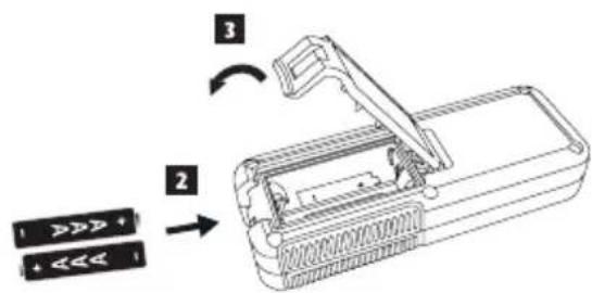
Installing the DEWALT 20V Battery Pack
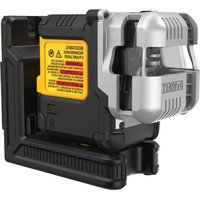
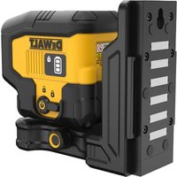
1 Position the fully-charged DEWALT 20V battery pack so the release button (Figure D ①) is facing away from you and to the right.
2 Press and hold down the release button (Figure ①) on the battery pack.
3 Slide the battery pack all the way into the track on the side of the laser (Figure ① ②).
4. Release the button on the battery pack.
Removing the Battery Pack
1 Press and hold the release button on the battery pack (Figure ①).
2. Slide the battery pack out of the track on the laser.
3. Release the button on the battery pack.
4. To recharge the battery pack, insert it into the charger, as described in the Battery Safety Manual.

WARNING: Batteries can explode or leak, and can cause injury or fire. To reduce this risk, follow the instructions in the Battery Safety Manual.
Storing Battery Packs
- The best storage place is one that is cool and dry, and away from direct sunlight and excess heat or cold.
- Long storage will not harm the battery pack or charger. Under proper conditions, they can be stored for 5 years or more.
SAVE THESE INSTRUCTIONS FOR FUTURE USE
Installing the Coin Cell Battery
A coin cell battery should already be installed in the bottom of the laser unit (Figure ③) so it is ready to use the Bluetooth connection, after you remove the battery protector. To remove the battery protector on your new laser, or replace the coin cell battery in the future, follow these steps.
- Carefully turn the laser upside down.
- On the bottom of the laser, unscrew the battery compartment cover, which is marked 3V CR2430.
- Lift off the battery compartment cover and remove the coin cell battery.
- If your laser is new, remove the battery protector (round disc), and then re-insert the same coin cell battery.
- If your laser is not new, insert a new 3V CR2430 coin cell battery into the battery compartment.
- Carefully place the battery compartment cover back in the correct position and use the screws to secure the cover in place on the bottom of the laser unit.
Bluetooth
THE BLUETOOTH® WORD MARK AND LOGOS ARE REGISTERED TRADEMARKS OWNED BY BLUETOOTH SIG, INC. AND ANY USE OF SUCH MARKS BY DEWALT IS UNDER LICENSE. APPLE AND THE APPLE LOGO ARE TRADEMARKS OF APPLE INC., REGISTERED IN THE U.S. AND OTHER COUNTRIES. APP STORE IS A SERVICE MARK OF APPLE INC., REGISTERED IN THE U.S. AND OTHER COUNTRIES. GOOGLE PLAY AND THE GOOGLE PLAY LOGO ARE TRADEMARKS OF GOOGLE INC.
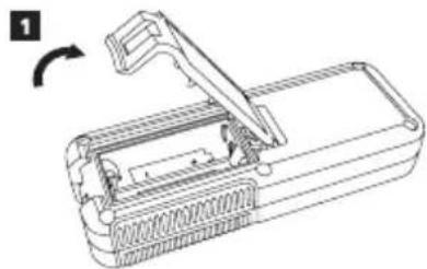
Installing Batteries in the Remote
Load new AAA batteries into the remote so you can use it with the laser unit.
- On the bottom of the remote, lift up the latch to open the battery compartment cover (Figure ⑥).
2 Insert two new, high-quality, name brand AAA batteries, making sure to position the - and + ends of each battery as noted inside the battery compartment (Figure ⑤ ②).
3 Push the battery compartment cover closed until it snaps into place (Figure ⑤ ③).
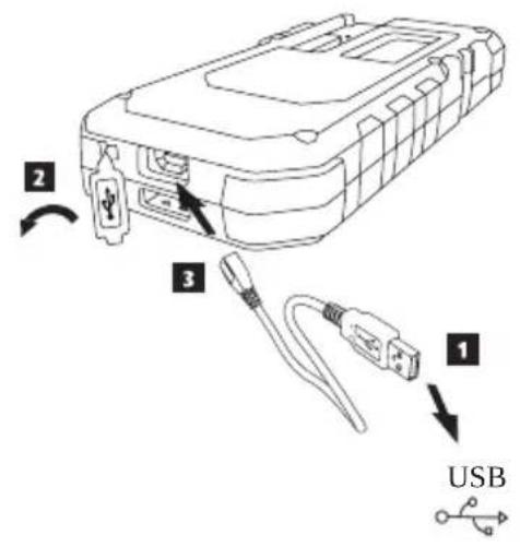
Charging the Detector
The Digital Laser Detector is powered by a Li-ion battery. To charge the battery.
- Insert the USB end of the charging cable into a USB port (Figure E ①).
- On the Detector, pull the Micro USB port cover (Figure ②) off and to the side.
- Insert the Micro USB end of the charging cable into the Detector's Micro USB port (Figure E ③).
4 Allow the Detector time to fully-charge. The LED on the Detector will remain Red as the battery is charging (Figure F 13). - When the LED on the Detector turns Green, remove the charging cable.
The RBRC® Seal
The RBRC (Rechargeable Battery Recycling Corporation) Seal on the nickel cadmium, nickel metal hydride or lithium-ion batteries (or battery packs) indicates that the costs to recycle these batteries (or battery packs) at the end of their useful life have already been paid by DeWALT. In some areas, it is illegal to place spent nickel cadmium, nickel metal hydride or lithium-ion batteries in the trash or municipal solid waste. Call 2 Recycle program provides an environmentally co


Call 2 Recycle, Inc., in cooperation with DeWALT and other battery users, has established the program in the United States and Canada to facilitate the collection of spent nickel cadmium, nickel metal hydride or lithium-ion battery. Help protect our environment and conserve natural resources by returning the spent nickel cadmium, nickel metal hydride or lithium-ion batteries to authorized DeWALT service center or to your local retailer for recycling. You also contact your local recycling center for information on where to drop off spent battery. RBRC® is a registered trademark of Call 2 Recycle, Inc.
Operating Tips
- To extend battery life per charge, turn the laser off when it is not in use.
- To ensure the accuracy of your work, check the laser calibration often. Refer to Checking the Calibration.
- Before attempting to use the laser, make sure the tool is positioned on a relatively smooth, secure surface.
- Always mark the center of the laser line or dot. If you mark different parts of the beam at different times you will introduce error into your measurements.
- To increase working distance and accuracy, set up the laser in the middle of your working area.
- When attaching to a tripod or wall, mount the laser securely.
- When working indoors, a slow rotary head speed will produce a visibly brighter line, a faster rotary head speed will produce a visibly solid line.
- To increase beam visibility, wear Laser Enhancement Glass es (Figure) and/or use a Laser Target Card (Figure) to help find the beam.
- Extreme temperature changes can cause movement or shifting of building structures, metal tripods, equipment, etc., which can effect accuracy. Check your accuracy often while working.
- If the laser is dropped or has suffered a sharp blow, have the calibration system checked by a qualified service center before using the laser.
Turning the Laser On
Insert the fully charged DEWALT 20V battery pack as shown in FigureD.
2.1Gently press the power button to power ON the laser:
The power LED indicator light (Figure) will illuminate.
- Self-leveling mode is activated automatically and the laser unit will self-level. Once the laser unit is level, the beam will rotate clockwise once at 600RPM.
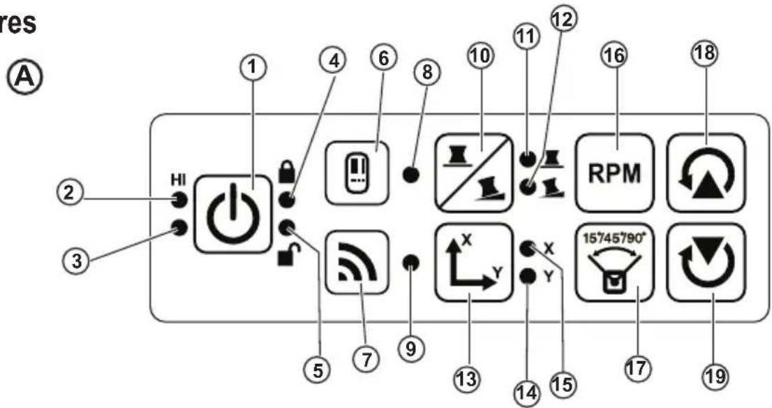
30 sec. after the last button press, HI Mode (Height of Instrument, Anti-Drift) is activated automatically and the HI LED (FigureA ②) will illuminate. (You can disable HI Mode by holding down the Slope Mode button for 2 secs. The laser will beep twice and the HI Mode LED will turn off. NOTE: when HI Mode is disabled, the laser cannot detect any movement after setup, so accuracy cannot be guaranteed.)
- Press (Figure A16) to adjust the Rotation Speed of the laser beam through its 4 preset speeds (150, 300, 600, and 1200 RPM). NOTE: Accuracy is best optimized at 600 RPM or less.
-
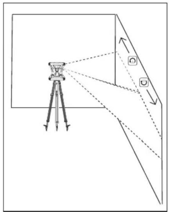
To change the Direction of the laser beam while in self-leveling mode, press or (Figure A18 or 19).
Press the Scan Mode button (Figure A 17) to set the laser to scan in 0^ , 15^ , 45^ , or 90^ angle mode. -
is used to make the laser head sweep back and forth, creating a short, bright laser line. This short line is much brighter and more visible than when the unit is in full rotation mode.
The direction of the scan zone can be controlled with the arrow buttons and (Figure or) -
If you press the Slope Mode button to turn ON Slope Mode, the unit automatically engages the X-Axis. This allows you to slope the laser in the direction of the X-Axis, as indicated by the X mark on the top roll cage.
-
In certain situations, it may be desirable to slope the laser in the Y-axis. The direction of Slope Mode can be changed back and forth between the Y-axis and the X-axis by pressing the X-Y axis button (Figure A 3).
-
If using X-axis slope, the X-axis LED (Figure A 15) will light, or if using Y-axis slope, the Y-axis LED (Figure A 14) will light instead.
-
When in Slope Mode, press or to tilt the laser head up and down (adjust the elevation of the laser beam).
Each quick press of or will move the slope by 0.01^ (1/16" @ 30ft. or 1.6mm @ 10m).
If you press and hold or between 2 sec - 10 sec, the slope will move from 0.01^ /sec to 0.2^ /sec.
- If you press and hold or longer than 10 sec, the slope will move 0.2^ /sec.
- To turn off the laser unit, press and hold the power button for 3 secs.
- BEFORE using the laser for your first project, follow the instructions for Checking the Calibration.
NOTE: When you press the Slope Mode button again, the laser will return to self-level mode.
Checking the Calibration
Field calibration checks should be done frequently. This section provides instructions for performing simple field calibration checks of your DeWALT Rotary Laser. Field calibration checks do not calibrate the laser. That is, these calibration checks do not correct errors in the leveling or plumb capability of the laser. Instead, these checks indicate whether or not the laser is providing a correct level and plumb line. These checks cannot take the place of professional calibration performed by a DeWALT service center.
Level Calibration Check (X-axis)
Position a tripod securely on the floor between two walls that are at least 50 feet apart. The exact location of the tripod is not critical.
2. Make sure that the top of the tripod is roughly level.
- The laser will self-level only if the top of the tripod is within ± 5^ of level.
- If the laser is set up too far out of level, it will beep when it reaches the limit of its leveling range. No damage will be done to the laser, but it will not operate in an "out of level" condition.
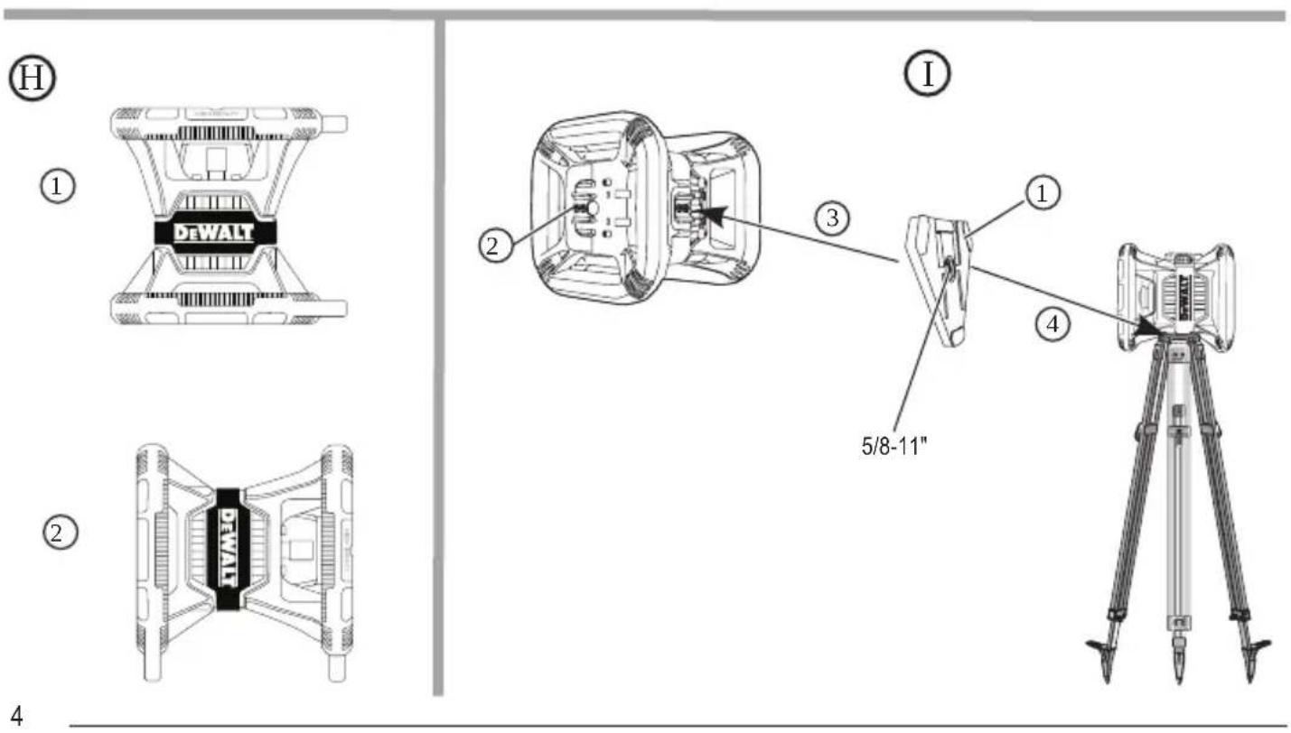
3 Attach a tripod adapter (Figure ①) to the laser unit. The adapter may be assembled to the bottom for level mode (Figure ②) or to the side for plumb (vertical) mode (Figure ①③).
4. Place the laser with the attached adapter on the tripod and screw the threaded knob on the tripod into the female thread on the tripod adapter.
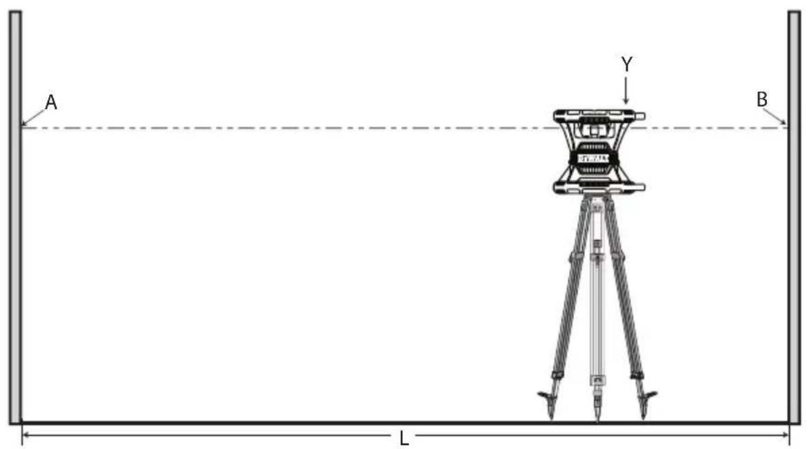
5. Position the laser unit on the tripod so that the laser's X-axis points directly toward one of the walls (Figure M 1).
6. Turn the laser unit on and allow it to self-level.
7. Where the beam appears on the left wall, mark point A, and where the beam appears on the right wall mark point B.
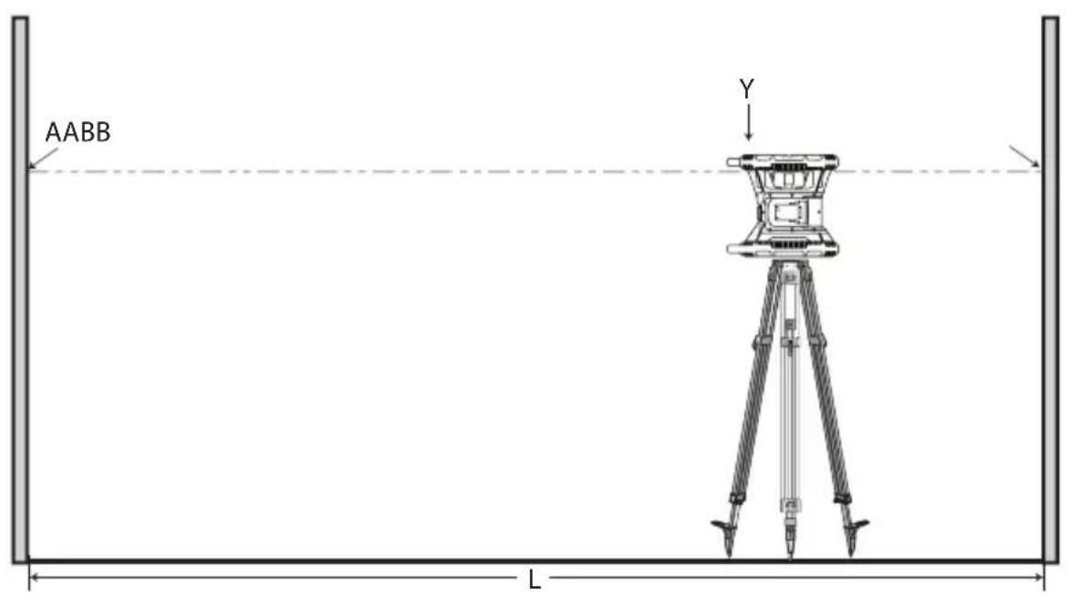
8. Turn the laser unit 180^ so that the X-axis points directly toward the opposite wall (Figure M 2).
9. Allow the laser unit to self-level.
10. Where the beam appears on the left wall, mark point AA, and where the beam appears on the right wall mark point BB.
11 Calculate the Total Error using the following equation:
$$ \text {T o t a l E r r o r} = (\mathrm {A A - A}) - (\mathrm {B B - B}) $$
- If your Total Error measurement is greater than the Allowable Error for the corresponding Distance Between Walls in the following table, the laser must be serviced at an authorized service center.
| L (Distance Between Walls) | Allowable Error |
| 40' (15m) 3/64" (1.5mm) | |
| 50' (20m) 1/16" (2mm) | |
| 70' (25m) 3/32" (2.5mm) | |
| 100' (30m) | 1/8" (3mm) |
E
Level Calibration Check (Y-axis)
- Set up a tripod between two walls that are at least 50 feet apart. The exact location of the tripod is not critical.
-
Make sure that the top of the tripod is roughly level.
-
The laser will self-level only if the top of the tripod is within ± 5^ of level.
-
If the laser is set up too far out of level, it will beep when it reaches the limit of its leveling range. No damage will be done to the laser, but it will not operate in an "out of level" condition.
-
Attach a tripod adapter (Figure ⑥①) to the laser unit. The adapter may be assembled to the bottom for level mode (Figure ⑥②) or to the side for plumb (vertical) mode (Figure ①③).
- Place the laser with the attached adapter on the tripod and screw the threaded knob on the tripod into the female thread on the tripod adapter.
- Position the laser unit on the tripod so that the laser's Y-axis points directly toward one of the walls (Figure N 1).
- Turn the laser unit on and allow it to self-level.
- Where the beam appears on the left wall, mark point A, and where the beam appears on the right wall mark point B.
- Turn the laser unit 180^ so that the Y-axis points directly toward the opposite wall (Figure ②).
- Allow the laser unit to self-level.
- Where the beam appears on the left wall, mark point AA, and where the beam appears on the right wall mark point BB.
Calculate the Total Error using the following equation:
Total Error = (AA-A) - (BB-B)
- If your Total Error measurement is greater than the Allowable Error for the corresponding Distance Between Walls in the following table, the laser must be serviced at an authorized service center.
| L (Distance Between Walls) Allowable Error |
| 40' (15m) 3/64" (1.5mm) |
| 50' (20m) 1/16" (2mm) |
| 70' (25m) 3/32" (2.5mm) |
| 100' (30m) 1/8" (3mm) |
Plumb Error Check
Perform this check using a wall that is no shorter than the tallest wall for which this rotary laser will be used (Figure ①).
Using a standard plumb bob as a reference, mark the top and bottom of a wall. (Be sure to mark the wall and not the floor or ceiling).
2. Position the rotary laser securely on the floor approximately 3^ (1m) from the wall.
3. Turn the laser on and point the laser dot at the mark on the bottom of the wall.
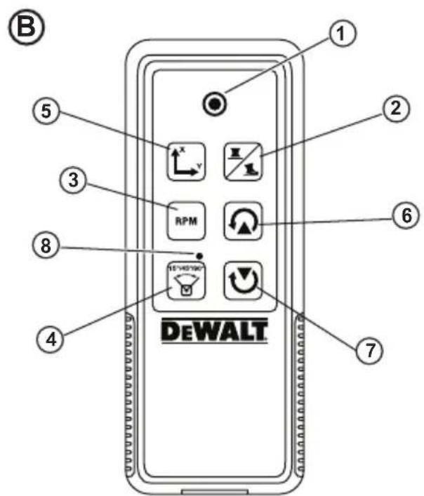
4 Using the or arrow on the Remote Control (Figure B6 or B7), rotate the dot upwards.
5. If the center of the dot scans over the mark on the top of the wall, the laser is properly calibrated.
Using the Laser
Using the Laser on a Tripod
Position a tripod securely and set it to the desired height. Make sure that the tripod has a 5/8 -11 threaded screw to ensure secure mounting of the laser unit.
2. Make sure that the top of the tripod is roughly level.
- The laser will self-level only if the top of the tripod is within ± 5^ of level.
- If the laser is set up too far out of level, it will beep when it reaches the limit of its leveling range. No damage will be done to the laser, but it will not operate in an "out of level" condition.
Attach a tripod adapter (Figure G 1) to the bottom of the laser unit (Figure G 2).
Place the laser with the attached adapter on the tripod and screw the threaded knob on the tripod into the female thread on the tripod adapter.
Turn the laser ON and allow it to self-level in horizontal (level) mode (Figure 1).
If you want to use the laser in vertical (plumb) mode, follow these steps while the laser is still ON:
- Carefully remove the laser unit from the tripod.
- Remove the tripod adapter (Figure 1) from the bottom of the laser unit (Figure 2) and attach it to the side (Figure 3).
- With the laser in the vertical (plumb) position, attach the laser unit to the tripod (Figure 14). The Dot rotates down to 6 o'clock.
- Press to make sure the laser rotates.
Adjust the rotation speed and controls, as desired (Figure P).
Using the Laser on a Floor
The laser level can be positioned directly on the floor for leveling and plumbing applications such as framing walls.
Place the laser on a relatively smooth and level surface where it will not be disturbed or exposed to vibration.
Position the laser for a level setting (Figure H 1).
Turn the laser ON and allow it to self-level in level (horizontal) mode.
If you want to use the laser in plumb (vertical) mode, carefully turn the laser so the keypad is at the top (Figure 2). The Dot rotates down to 6 o'clock. Press to make sure the laser rotates.
Adjust the rotation speed and controls, as desired (Figure P).
NOTE:
The laser will be easier to set up for wall applications if the rotation speed is set to 0 RPMs and the remote control is used to line up the laser with control marks. The remote allows one person to set up the laser.
Using the Laser With a Laser Detector
How the Detector works
Some laser kits include a DeWALT Digital Laser Detector. The DeWALT Digital Laser Detector allows you to locate a laser beam emitted by a rotary laser in bright light conditions or over long distances.
- The detector can be used in both indoor and outdoor situations where it is difficult to see the laser beam.
- The detector is not for use with non-rotating lasers but is compatible with most rotary red-beam (DW080LRS) and green beam (DW080LGS) lasers.
- The detector can be set to indicate the location of the beam to either the nearest 5/64 (2 mm) or the nearest 3/64 (1 mm).
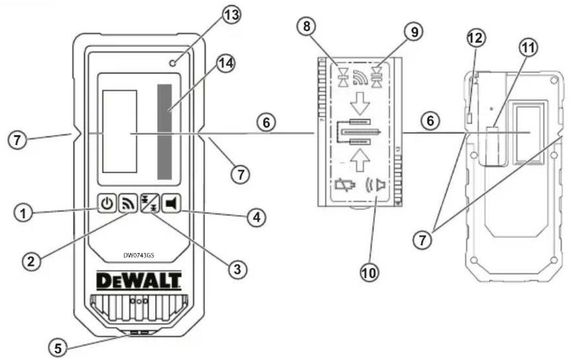
- The detector gives both visual signals through the display window (Figure F 6) and audio signals through the speaker (Figure F 5) to indicate the location of the laser beam.
Detector's Indicators
| Above Grade | Slightly Above Grade | On Grade | Slightly Below Grade | Below Grade | |
| Audible | Fast | Fast | Steady | Slow | Slow |
| Signal | Beep | Beep | Tone | Beep | Beep |
| Display Icon |

-
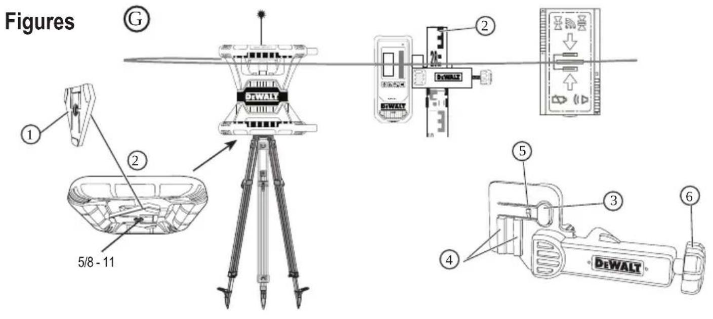
The DEWALT Digital Laser Detector can be used with or without the detector clamp. When used with the clamp, the detector can be positioned on a grade rod, leveling pole, stud, or post (Figure G). To connect the detector to the clamp:
-
Push in the clamp latch (Figure G 3).
-
Slide the tracks on the clamp (Figure ⑥④) around the rail on the back of the detector (Figure ①⑪) until the button (Figure ⑥⑤) on the clamp snaps into the latch hole on the back of the detector (Figure ①⑫).
-
Turn the clamp knob (Figure 6) counterclockwise to open the jaws on the clamp.
-
Place the clamp on the rod (Figure G 2) so that the detector is positioned at the height needed to work with the laser.
-
Turn the clamp knob (Figure 6) clockwise to secure the clamp on the rod.
Using the Detector
- Set up and position the rotary laser that you will be using according to the manufacturer's directions. Turn the laser on and make sure the laser is rotating and emitting a laser beam.
-
Press the power button once on the detector to turn the detector on.
3 On the bottom of the display window, notice the speaker icon (Figure F 10). -
To decrease the volume of the audible signal, press the volume button (Figure F 4); both half circles next to the speaker icon (Figure F 10) will disappear.
To turn off the audible signal, press the volume button (Figure F 4) until the speaker icon dissapears from the display window. -
On the top of the display window, view the Accuracy Mode icon (Figure ⑧).
-
indicates that the detector will give an "on grade" reading only when the laser beam is on grade or no more than 1/25 (1 mm) above or below it.
-
To change the Accuracy Mode to to have the detector give an "on grade" reading when the laser beam is on grade or approximately 1/8 (3 mm) above or below it, press the Accuracy Mode button (Figure F ③ once. Then figure ⑨) appears on the display window.
-
Position the detector so that the Beam Detection window (Figure F 14) is facing the laser beam produced by the rotary laser (Figure G). Move the detector up or down within the approximate area of the beam, until you have centered the detector.
-
Use the marking notches (Figure ⑦) to accurately mark the position of the laser beam.
-
To turn the detector off.
-
On the detector, press for 3 seconds.
- If a rotary laser beam does not strike the detector's beam detection window, or if no detector buttons are pressed, within 30 minutes, the detector will shut itself off.
Controlling the Laser Remotely
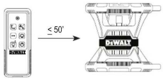
You can control the laser unit remotely in either of these 3 ways:
-
From up to 50^ away, you can use the remote to control the laser unit (Figure ①①). IR sensors will maintain communication between the remote and the laser unit.
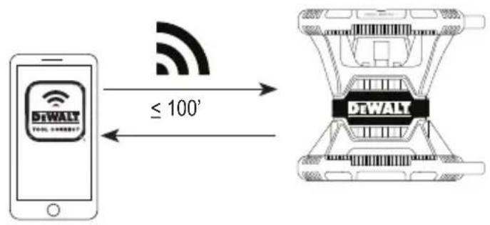
-
From up to 100 away, you can use the DEWALT® Tool Connect™ Application on your Bluetooth® device to connect to the laser unit (Figure J2).
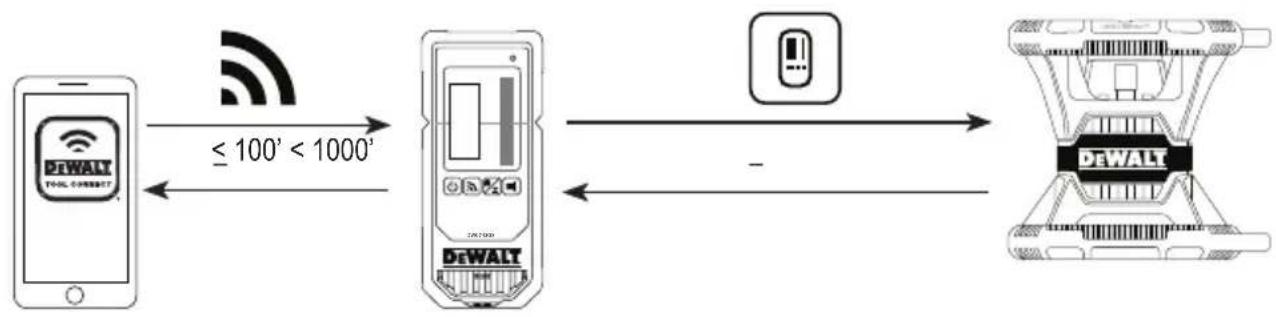
- From up to 1100 away, you can control the laser unit by using the DEWALT® Tool Connect™ Application on your Bluetooth device to connect to the detector that is connected to the laser unit (Figure ①③). You must press the Detector button (figure A6) on the laser in order to connect the detector to the laser unit.
Controlling the Laser from up to 50' Away
The DW080LRS/LGS remote control allows you to operate and set up the laser from up to 50^ away. The LED light on the remote control (Figure B 1) indicates a signal is being transmitted from the DW080LRS/LGS laser unit.
You can use all the buttons on the remote's keypad to control the laser unit. To completely power OFF a DW080LRS/LGS laser unit using the Remote keypad, simultaneously press the X-Y axis button (Figure B5) and the Slope Mode button (Figure B2).
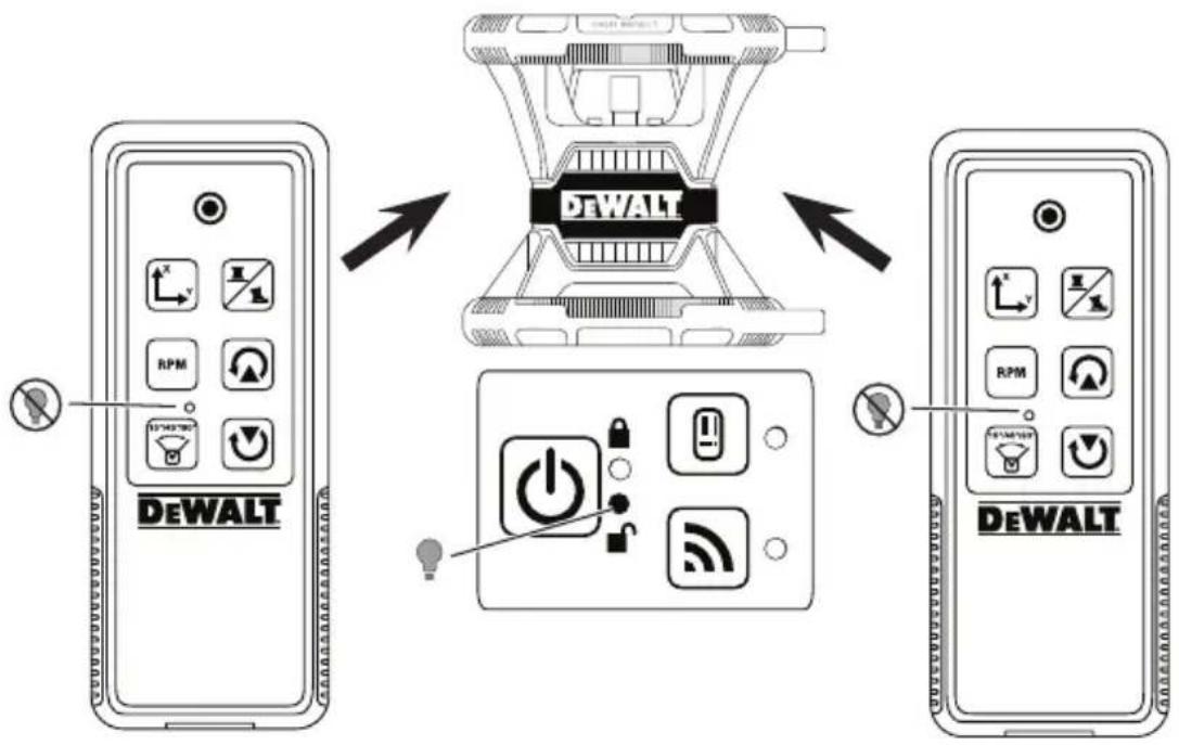
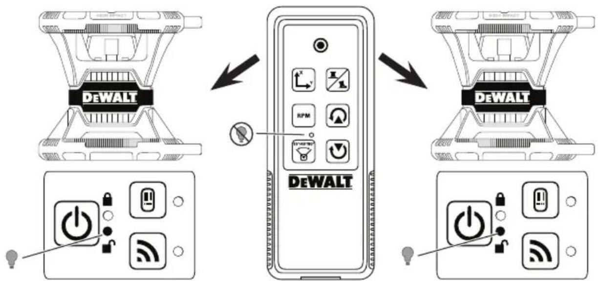
By default, the laser unit is not paired to a remote (the laser unit is in Public mode). LEDs on the laser unit and the remote will indicate that they are not paired.
| UNLOCKED in Public Mode | LOCKED in Private Mode | |
| Description A | laser is in Public Mode if it is not paired with a remote. | A laser is in Private Mode if it is paired with a remote. |
| A remote is in Public Mode if it is not paired with a laser. | A remote is in Private Mode if it is paired with a laser. | |
| Control A Public laser can be controlled by more than one Public remote (Figure ①). | A Private laser can only be controlled by the remote to which it is paired (Figure ⑤). | |
| A Public remote can control more than one Public laser (Figure ②). | A Private remote can only control the laser to which it is paired (Figure ⑥). | |
| LEDs | The unlocked LED will be lit on the laser keypad (Figure ① and ②). | The locked LED on the laser will be lit (Figure ⑤). |
| The locked LED on the remote will NOT be lit (Figure ① and ②). | The locked LED on the remote WILL be lit (Figure ⑥). | |
Pairing the Laser to a Remote
To pair the laser unit to one remote, simultaneously press and hold on the laser keypad and on the remote. LEDs on the laser and the remote will indicate that they are paired (in Private mode).
- The laser unit will beep twice and the locked LED (Figure A4) on the laser keypad will blink twice and then remain green to indicate that currently only one remote can control the laser (Figure L).
- The locked LED on the remote (Figure B.8) will blink twice and then remain red.
If You Stop Using a Paired Remote
If you stop using a remote that has been paired with a laser unit (remote is in Private mode), the remote will automatically reset back to Public mode. You will not be able to use the remote to control the laser unit. The Lock LED on the laser keypad will remain lit, but you can only use the laser keypad to control the laser.
| If... Result | |
| No buttons are pressed on the remote keypad right after it is paired with a laser unit. | Within 1 minute, the remote will be reset back to Public mode. |
| Buttons are pressed on the remote keypad after it is paired with a laser unit. | After 8 hours, the remote will be reset back to Public mode. |
To change the remote back to Private mode so it can again control the laser unit, press and hold on the remote keypad.
If You Turn OFF a Paired Laser Unit
If you use the laser keypad to turn off a laser unit that is paired with a remote, turning the laser back on will not automatically re-establish the Private connection with the same remote again.
- The remote that had been paired with the laser unit will remain in Private mode with the Lock LED still lit, but it will not be able to control any laser unit.
- The laser unit will default to Public mode and can be controlled by any remote except the remote that is still in private mode.

To unlock the remote and reset it back to Public mode so it can be used to control any laser unit again, press and hold the RPM button on the remote keypad.
Resetting a Remote from Private Mode
When a remote is in Private Mode with a laser unit, you may need to reset the remote in order to use it with the laser unit again.
| Scenario How to Recover | |
| When pressing and holding on the laser keypad, the laser entered No Remote mode. | On the laser keypad, press and hold the RPM button to return the laser to Public mode so it can be controlled by any remote. |
| The laser unit entered Private mode while paired with another remote. | Reset the laser unit back to Public mode. On the laser keypad, either. • Press for 3 sec to turn the power off and then press again to turn the power back on, OR • Press and hold the RPM button. |
| If the Lock LED is lit on the remote, the remote has been paired with another rotary laser. | Press and hold the RPM button on the remote to reset it to Public mode. |
Controlling the Laser from up to 100' Away
You can use Bluetooth® capability to pair the laser with the DEWALT® Tool Connect™ application on your cell phone, and then use your cell phone to control the laser (Figure ① ②).
- From either Google Play or Download the DEWALT Tool Connect™ application to your cell phone and then open the application.
- On the laser's keypad, press turn the laser on.
- Pair the DEWALT® Tool Connect™ application to the laser via a Bluetooth® connection.
| First Time Pairing Paired | Before |
| 1. On the DeWALT® ToolConnect™ application, click +2. In the list of DeWALT product types, select Rotary Laser.3. Enter a Name for the rotary laser (e.g., DW080LRS/LGS).4. On the laser keypad, press and hold for 3-5 sec until the Bluetooth® connection turns on (blue LED starts blinking).5. When the application lists the laser's model number as IN RANGE, select it. | On the laser keypad, press to turn on the Bluetooth® connection. |
NOTE:
If the Bluetooth connection does not turn on, replace the 20V battery.
- On the DEWALT Tool Connect™ application, select the DW080LRS/LGS rotary laser.
-
The DEWALT® Tool Connect™ application will display information about the laser on the Diagnostics screen:
-
If the current settings are one of the "favorite settings" you have saved for the laser, it will display the name of that setting (e.g., Main St - Site 1).
- If the laser is dropped, disturbed, etc., it will send messages to the Tool Connect™ application to inform you.
- If the Tracking feature is on, the application will know where the laser is and will let you know if the laser has been taken and is now out-of-range. (The Coin Cell battery enables the Tracking feature.)
6. Select ACTIONS.
- If you are using more than one rotary laser and need to check which laser is paired with the application, press the Identify button at the bottom of the screen. On the paired laser, the blue LED next to will blink.
- If you need to, you can enable, disable, or unpair the laser.
7 Select Rotary Control to change the setting for the rotary laser.
- When RPM is selected, choose the rotation speed (150, 300, 600, or 1200).
- Select and choose the rotation angle (0, 15, 45, 90, or 360) and the rotation direction (or
-
Select and choose the Slope Setting, Axis Setting (X or Y), Slope Configuration (% or degree), # degree or %.
-
Use your cell phone to control the laser.
- When you are ready, turn the laser off from the Diagnostic screen.
Controlling the Laser from up to 1100' Away
You can use Bluetooth® capability to pair the Detector DW0743DR (Red laser) or DW0743DG (Green laser) with the DEWALT® Tool Connect™ application on your cell phone, and then use your cell phone to control the laser (Figure ①③).
- From either or App Store, download the DEWALT Tool Connect™ application to your cell phone.
- On the laser keypad, press turn the laser on.
- On the laser keypad, see if the blue LED next to is lit. If the blue LED is already lit, the laser is probably already paired with another smart device. You will need to unpair the laser from the other device before you can pair it to the DeWALT® Tool Connect™ application.
- Pair the DEWALT® Tool Connect™ application to the laser via a Bluetooth® connection.
| First Time Pairing Paired | Before |
| 1. On the DEWALT® Tool Connect™ application, click + 2. In the list of DEWALT product types, select Rotary Laser. 3. Enter a Name for the rotary laser (e.g., DW080LRS/LGS). 4. On the laser keypad, press and hold 3-5 sec until the Bluetooth® connection turns on (blue LED starts blinking). 5. When the application lists the laser's model number as IN RANGE, select it. | On the laser keypad, press to turn on the Bluetooth® connection. The blue LED will illuminate. |
NOTE:
If the Bluetooth® connection does not turn on, replace the DEWALT 20V battery.
- On the laser keypad, press Figure connection to the detector.
A 6) to turn on the
- On the DEWALT® Tool Connect™ application, press Add a detector.
- Enter a Name for the detector and press Connect.
- Turn on the detector and then press turn on the Bluetooth connection.
-
The DEWALT Tool Connect™ application will display information about the laser on the Diagnostics screen:
-
If the current settings are one of the "favorite settings" you have saved for the laser, it will display the name of that setting (e.g., Main St - Site 1).
- If the laser is dropped, disturbed, etc., it will send messages to the Tool Connect™ application to inform you.
- If the Tracking feature is on, the application will know where the laser is and will let you know if the laser has been taken and is now out-of-range. (The Coin Cell battery enables the Tracking feature.)

10 Select ACTIONS.
- If you are using more than one rotary laser and need to check which laser is paired with the application, press the Identify button at the bottom of the screen. On the paired laser, the blue LED next to will blink.
-
If you need to, you can enable, disable, or unpair the laser.
-
Select Rotary Control to change the setting for the rotary laser.
-
When is selected, choose the rotation speed (150, 300, 600, or 1200).
- Select and choose the rotation angle (0, 15, 45, 90, or 360) and the rotation direction (or
- Select and choose the Slope Setting, Axis Setting (X or Y), Slope Configuration (% or degree), # degree or %.
12 Use your cell phone to control the laser.
13. When you are ready, turn the laser off from the Diagnostic screen.
Unpairing the Detector from the Application
To unpair the Detector connection to the DeWALT® Tool Connect™ application and return to pairing the application with the laser unit, follow these steps.
1 On the DEWALT® Tool Connect™ application, unpair the detector connection on the Diagnostics screen.
2. Turn off the detector.
3 On the laser keypad, press figure A6 to turn off the connection with the detector. Once the detector is unpaired from the laser, the laser will automatically switch back to being paired with the DeWALT® Tool Connect™ application.
4 You can then make sure that the laser unit is paired with the application. On the ACTIONS screen, select the Identify button at the bottom of the screen. The blue LED will flash on the paired laser unit.
Then, if you want to unpair the laser unit from the DEWALT® Tool Connect™ application, you can unpair it from the Actions screen.
Accessories
Recommended accessories for use with your tool are available for purchase at your factory-owned local service center.

WARNING:
Since accessories other than those offered by DEWALT have not been tested with this laser, use of such accessories with this laser could be hazardous. To reduce the risk of injury, only use DEWALT® accessories that are recommended for use with this rotary laser.
If you need assistance in locating any accessory, please visit our website www.DeWALT.com
Mounting Bracket
Some laser kits include a mounting bracket, which can be used for attaching the tool to a track or to a ceiling grid to aid in acoustical ceiling installation. Follow the directions below for using the mounting bracket.

CAUTION:
Before attaching the laser level to wall track or ceiling angle, be sure that the track or angle is properly secured.
1 Place the laser on the mounting base (Figure 5) aligning the 5/8-11 screw hole on the tripod adapter (Figure 1), attached to the bottom of the laser with the hole (Figure 6) in the mounting base.
2. Turn the mounting knob (Figure ③) to secure the laser.
3 With the bracket's measuring scale (Figure ⑦) facing you, loosen the clamp locking knob (Figure ⑧) to open the clamp jaws.
4. Position the clamp jaws around the wall track or ceiling angle and tighten the clamp locking knob (Figure ⑧) to close the clamp jaws onto the track. Be sure that the clamp locking knob is securely tightened before proceeding.
CAUTION:
Always use a ceiling wire hanger or equivalent material, in addition to the clamp locking knob, to help secure the laser level while mounting it to a wall. Thread the wire through the handle of the laser level. DO NOT thread the wire through the protective metal cage. Additionally, screws may be used to fasten the bracket directly to the wall as a backup. Screw holes (Figure 9) are located at the top of the bracket.
Using the base leveling knob (Figure 2) approximate a level position from the wall.
The tool can be adjusted up and down to the desired height for working. While supporting the mounting base, loosen the locking knob on the left side of the bracket (Figure 1).
Turn the adjustment knob on the right side of the bracket (Figure 4) to move the laser level up and down to set your height. Use the measuring scale (Figure 7) to pinpoint your mark.
NOTE: It may be helpful to turn the power on and turn the rotary head so that it puts a dot on one of the laser scales. The DEWALT target card is marked at 1 - 1 / 2 (38 mm), so it may be easiest to set the offset of the laser to 1 - 1 / 2 (38 mm) below the track.
Once you have positioned the laser at the desired height, tighten the locking knob (Figure 1) to maintain this position.
Construction Grade Rod
DANGER:
NEVER attempt to use a grade rod in a storm or near overhanging electric wires. Death or serious personal injury will occur.
Some laser kits include a grade rod. The DEWALT Grade Rod is marked with measurement scales on both sides and is constructed in telescoping sections. A spring-loaded button actuates a lock to hold the grade rod at various lengths.
The front of the grade rod has the measurement scale starting at the bottom. Use this for measuring from the ground up when grading or leveling jobs.
The back of the grade rod is designed to measure the height of ceilings, joists, etc. Fully extend the top section of the grade rod until the button locks into the previous section. Extend that section either until it locks into the adjacent section or until the grade rod touches the ceiling or joist. The height is read where the last extended section exits the previous lower section (Figure R).
Target Card
Some laser kits include a Laser Target Card (Figure s) to aid in locating and marking the laser beam. The target card enhances the visibility of the laser beam as the beam crosses over the card. The card is marked with standard and metric scales. The laser beam passes through the red plastic and reflects off of the reflective tape on the reverse side. The magnet at the top of the card is designed to hold the target card to ceiling track or steel studs to determine plumb and level positions. For best performance when using the Target Card, the DEWALT logo should be facing you.
Laser Enhancement Glasses
Some laser kits include Laser En hancement Glasses (Figure T). These glasses improve the visibility of the laser beam under bright light conditions or over long distances when the laser is used for interior applications. These glasses are not required to operate the laser.
CAUTION:
These glasses are not ANSI approved safety glasses and should not be used while operating other tools. These glasses do not keep the laser beam from entering your eyes.
CAUTION:
To reduce the risk of serious injury, never stare directly into the laser beam with or without these glasses.
E Maintenance
Laser Cleaning and Storage
- Under some conditions, the glass lens may collect some dirt or debris. This will affect beam quality and operating range. The lens should be cleaned with a cotton swab moistened with water.
- The flexible rubber shield can be cleaned with a wet lint-free cloth such as a cotton cloth. USE WATER ONLY — DO NOT use cleansers or solvents. Allow the unit to air dry before storing.
- To maintain the accuracy of your work, check the calibration of the laser often. Refer to Checking the Calibration.
- Calibration checks and other maintenance repairs can be performed by DEWALT service centers. Two free calibration checks are included under the DEWALT One Year Free Service Contract.
- When the laser is not in use, store it in the kit box provided.
- Do not store your laser in the kit box if the laser is wet. Dry exterior parts with a soft, dry cloth and allow the laser to air dry.
- Do not store your laser at temperatures below 0^ (-18^) or above 105^ (41^) .

WARNING:
Never use solvents or other harsh chemicals for cleaning the non-metallic parts of the tool. These chemicals may weaken the materials used in these parts. Use a cloth dampened only with water and mild soap. Never let any liquid get inside the unit; never immerse any part of the unit into a liquid. Never use compressed air to clean the laser.
Detector Cleaning and Storage
- Dirt and grease may be removed from the exterior of the detector using a cloth or a soft, non-metallic brush.
- The DEWALT Digital Laser Detector is waterproof. If you should drop the detector in mud, wet concrete, or a similar substance, simply hose the detector off. Do not use high pressure water (e.g., from a pressure washer).
- The best storage place is one that is cool and dry, and away from direct sunlight and excess heat or cold.
Troubleshooting
Laser Troubleshooting Height of Instrument Alert
The DW080LRS/LGS has a built-in alarm feature that alerts the operator if the unit is disturbed after the unit has self-leveled. The laser unit will stop rotating, the control panel LED indicator light will flash, and the beeper will sound.
Reset the laser unit so you can continue to use it:
- Press the power button for 3 sec.to turn the laser off. The power LED indicator light will no longer be illuminated.
- Press the power button turn the laser back on again.
Detector Troubleshooting
Detector will not Turn on
- Make sure the Li-ion battery is charged.
- If the detector is very cold, allow it to warm up in a heated area.
- Press the power button (Figure F to turn the detector on.
- If the detector still does not turn on, take the detector to a DeWALT service center.
Detector Makes no Sound
- Make sure the detector is on.
- Press the volume button (Figure F 4). It will toggle from high, to low, to mute. Make sure the speaker icon appears with two half circles (Figure F 10).
- Make sure the rotary laser is spinning and that it is emitting a laser beam.
4 If the detector is still not making any sound, take it to a DEWALT service center.
Detector Emits Sound but Does Not Display
1 If the detector is very cold, allow it to warm up in a heated area.
2. If the LCD display window is still not functioning, take the detector to a DEWALT service center.
Service and Repairs
Laser Service
Note: Disassembling the laser level will void all warranties on the product.
To assure product SAFETY and RELIABILITY, repairs, maintenance and adjustment should be performed by authorized service centers. Service or maintenance performed by unqualified personnel may result in a risk of injury. To locate your nearest DEWALT service center, go to www.DEWALT.com.
Detector Service
Except for batteries, there are no user serviceable parts in the Digital Laser Detector. Do not disassemble the unit. Unauth orized tampering with the laser detector will void all warranties.
Register Online
Thank you for your purchase. Register your product now for:
- WARRANTY SERVICE: Registering your product will help you obtain more efficient warranty service in case there is a problem with your product.
- CONFIRMATION OF OWNERSHIP: In case of an insurance loss, such as fire, flood or theft, your registration of ownership will serve as your proof of purchase.
FOR YOUR SAFETY: Registering your product will allow us to contact you in the unlikely event a safety notification is required under the Federal Consumer Safety Act.
Register online at www.dewalt.com/register.
Warranty
Go to www.DEWALT.com for the latest warranty information.
Laser Specifications
| DW080LRS DW080LGS | ||
| Laser Wavelength | 630-680nm 515-530nm630-680nm | |
| Laser Power/ Class | ≤ 5mw /CLASS 3R | |
| Rotation Speed 150, 300, 600, 1200 RPM | ||
| Self-Leveling Range | ± 5° | |
| Indoor Visible Range | 200' (60m) diameter 250' (80m) diameter | |
| Range with Detector | 2000' (600m) diameter | |
| Leveling Accuracy @ 600 RPM* | ± 1/16" per 100' (± 1.5mm per 30m) | |
| Power Source D | eWALT 20V battery | |
| Operating Temperature | 14°F to 122°F(-10°C to 50°C) | |
| Storage Temperature | -4°F to 158°F(-20°C to 70°C) | |
| Environmental Water & Dust Resistant to IP67 | ||
| * Standard ambient conditions per MIL-STD-810G. | ||
Detector Specifications
| DW0743RS & DW0743RG | |
| Accuracy - High ±1mm @ 30m | |
| Accuracy - Low ±2mm @ 30m | |
| Power Source Micro USB DC 5V | |
| Environmental Water & Dust | Resistant to IP54 |
Índice
Towson, Maryland 21286
www.DEWALT.com
Declaración de FCC
Towson, Maryland 21286
www.DEWALT.com
Towson, Maryland 21286
www.DEWALT.com
Declaração da FCC
Avisos da Industry Canada (IC), Canada
Towson, Maryland 21286
N639381 April 2019