BELLE PCX 500 - Vibratory plate Lescha - Free user manual and instructions
Find the device manual for free BELLE PCX 500 Lescha in PDF.
| Product type | Unidirectional vibratory plate |
| Brand | Lescha (Belle Group) |
| Model | BELLE PCX 500 |
| Available engine | Honda GX120, GX160, Robin EX13, EX17, Hatz 1B20 (diesel) |
| Fuel type | Unleaded gasoline or diesel depending on engine |
| Fuel tank capacity | 2.5 L (Honda GX120) to 3.6 L (Honda GX160) |
| Engine oil | SAE 10W30, quantity 0.6 L (Honda) to 1.1 L (Robin EX17) |
| Vibrator oil | Turbine oil 32, 0.4 L |
| Sound level | 105 dB(A) |
| Static pressure | 1400 to 1800 kg/m² (with Dual Force plate) |
| Dual Force technology | Yes, patented, two-stage compaction |
| Clutch | Centrifugal |
| Drive | Belt |
| Approximate weight | Approximately 150-200 kg (depending on engine) |
| Dimensions (L x W x H) | Not specified, approx. 1200 x 500 x 900 mm (estimate) |
| Required personal protective equipment | Safety glasses, gloves, ear protection, steel-toe shoes |
| Watering system | Optional (water bottle mounted at front) |
| Accessories | Paver pad, transport accessory |
| Warranty | 12 months (parts and labor) |
| Repairability | Original Belle Group parts, authorized service center |
Frequently Asked Questions - BELLE PCX 500 Lescha
User questions about BELLE PCX 500 Lescha
0 question about this device. Answer the ones you know or ask your own.
Ask a new question about this device
Download the instructions for your Vibratory plate in PDF format for free! Find your manual BELLE PCX 500 - Lescha and take your electronic device back in hand. On this page are published all the documents necessary for the use of your device. BELLE PCX 500 by Lescha.
USER MANUAL BELLE PCX 500 Lescha
natural_image
Abstract white bird-like shape on gradient background (no text or symbols)ALTRAD
GB Operators Manual 6
US Operators Manual 18
F Manuel De L'Opérateur 30
E Manual del Operador 42
P Manual de Operação 54
NL Handleiding 66
DK Betjeningsvejledning 78
D Bedienungshandbuch 90
I Manuale Dell'Operatore 102
S Bruksanvisning 114
NO Betjene Håndbok 126
SF Käyttöohje 138
PL Instrukcja Obsługi 150
RUS Руководство для оператора 162
EST Kasutusjuhend 174
LV Lietotāja rokasgrāmata 186
LT Naudojimo Instrukcija 198
BG Оператор Ръчен 210
GR χειριστής χειροποίητος 222
CZ Na'vod K Obzluze 234
RO Manual de Utilizare 246
HUN Kezelők Kézi 258
HR Uputstvo za rukovatelja 270

text_image
Belle GROUPPCX
350/400/450/500
natural_image
Technical line drawing of a mechanical device with no visible text or symbols- Spare Parts Book
- Pièces détachées
- Libro Despiece
- Lista de Peças
- Onderdelen Boekje
- Reservedele Skrift
- Ersatzteilhandbuch
- Manuale dei ricambi
- Bruksanvisning
- Bruksanvisning
- Varaosaluettelo
- Lista Części Zamiennych
- Запасные части Книга
- Varuosade nimekiri
- Rezerves daju saraksts
- Atsarginiu daliu sarašas
- Част Списък
- αντικατάσταση κομμάτια βιβλίο
- Cást Barevný pruh
- Lista Pieselor de Schimb
- Részek Oldalra döl
- Rezervni djelovi Knjiga
282
EC DECLARATION OF CONFORMITY / DECLARATION CE DE CONFORMITE / DECLARACIÓN DE CONFORMIDAD CE / DECLARAÇÃO CE DE CONFORMIDADE / EG-VERKLARING VAN OVEREENSTEMMING / EF OVERENSSTEMMELSESERKLAERING

We, Belle Group Sheen UK, Sheen, Nr. Buxton, Derbyshire, SK17 0EU, GB, hereby certify that if the product described within this certificate is bought from an authorised Belle Group dealer within the EEC, it conforms to the following EEC directives: 2006/42/CE (This directive replaces directive 98/37/EC), Electromagnetic Compatibility Directive 2004/108/CE (as amended by 89/336/EEC, 92/31/EEC & 93/68 EEC). The Waste Electrical and Electronic Equipment (WEEE) 2002/96/CE, the low voltage directive 2006/95/CE, BS EN ISO 12100-1:2003 Safety of machinery and associated harmonised standards, where applicable. Noise emissions conform to directive 2000/14/EC Annex VI, for machines under article 12 the notified body is AV Technology Limited, AVTECH house, Birdhall Lane, Cheadle Heath, Stockport, Cheshire, SK3 0XU, GB. Noise Technical Files are held at the Belle Group Head Office address which is stated above.

PRODUCT TYPE .... TYPE DE PRODUIT.... TIPO DE PRODUCTO.....
MODEL......
MODELE......
MODELO
SERIAL No......
DATE OF MANUFACTURE.
(GUARANTEED)....(GARANTIE)....(GARANTIZADO)
WEIGHT......
POIDS......
PESO......
TIPO DE PRODUCTO......
PRODUCTTYPE.... PRODUKTTYPE....
MODELO......
MODEL
MODEL......
NO. DE SÉRIE ......
SERIENUMMER......
SERIENR......
DATA DE FABRIC......
FABRICAGEDATUM ...... FREMSTILLINGSDATO ......
NIVEL DE POTÊNCIA GEMETEN LYDEFFEKTNIVEAU
DE SOM MEDIDO / GELUIDSSTERKTENIVEAU / MÄLT /
..(GARANTIDO) ......(GEGARANDEERD)
(GARANTERET)
PESO......
GEWICHT......
VÄEGT......
Signed by:
Signature:
Medido por:
Assinado por:
Getekend door:
Uunderskrevetaf:

text_image
O. NathRay Neilson
Managing Director - On behalf of BELLE GROUP (SHEEN) UK.
Place of Declaration - Sheen, Nr. Buxton, Derbyshire, SK17 0EU, UK
Lieu de déclaration - Sheen, Nr. Buxton, Derbyshire, SK17 0EU, UK
Sted i erklæring - Sheen, Nr. Buxton, Derbyshire, SK17 0EU, UK
Date of Declaration - 2007.
natural_image
Empty rectangular frame with dashed border (no text or symbols)Подпись:
Alla kirjutanud:
Paraksts:
Pasiraše:
Подпис:
Υπογραφή:

text_image
O.NahRay Neilson
Director General - in numele BELLE GROUP (SHEEN), UK
This manual has been written to help you operate and service the Plate Compactor safely. This manual is intended for dealers and operators of the Plate Compactor.
Foreword
The ‘Environment’ section gives instructions on how to handle the recycling of discarded apparatus in an environmentally friendly way. The ‘Machine Description’ section helps you to familiarise yourself with the machine’s layout and controls.
The ‘General Safety’ and ‘Health and Safety’ sections explain how to use the machine to ensure your safety and the safety of the general public.
The 'Start and Stop Procedure' helps you with starting and stopping the machine.
The 'Trouble Shooting' guide helps you if you have a problem with your machine.
The ‘Servicing’ section is to help you with the general maintenance and servicing of your machine.
The 'Warranty' Section details the nature of the warranty cover and the claims procedure.
The 'Dual Force' section shows the compaction specification the machine can achieve.
The 'CE certificate' section shows the standards that the machine has been built to.
Directives with regard to the notations.
Text in this manual to which special attention must be paid are shown in the following way:

CAUTION
The product can be at risk. The machine or yourself can be damaged or injured if procedures are not carried out in the correct way.

WARNING
The life of the operator can be at risk.

WARNING

WARNING
Before you operate or carry out any maintenance on this machine YOU MUST READ and STUDY this manual.
KNOW how to safely use the unit's controls and what you must do for safe maintenance. (NB Be sure that you know how to switch the machine off before you switch on, in case you get into difficulty.)
ALWAYS wear or use the proper safety items required for your personal protection. If you have ANY QUESTIONS about the safe use or maintenance of this unit, ASK YOUR SUPERVISOR OR CONTACT: BELLE GROUP (UK): +44 (0) 1298 84606

Contents
How to use this manual ....6
Warning 6
Machine Description ....7
Environment 7
Technical Data 8
Decals....9 - 10
General Safety 10
Health and Safety 11
Pre-Start Safety Checks 11
Start & Stop Procedure 12
Reasons for Compaction 12
Operating the Compactor ....13
Applications 13
Compaction Specification ....14
Trouble Shooting Guide ....14
Servicing 15
Assembly Instructions ....16
Fitting Instructions ....16
Dual Force Certificate 17
Warranty 17
C.E. Certificate 2
text_image
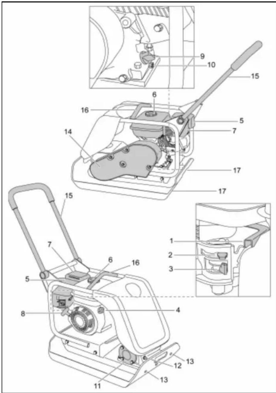
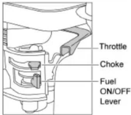
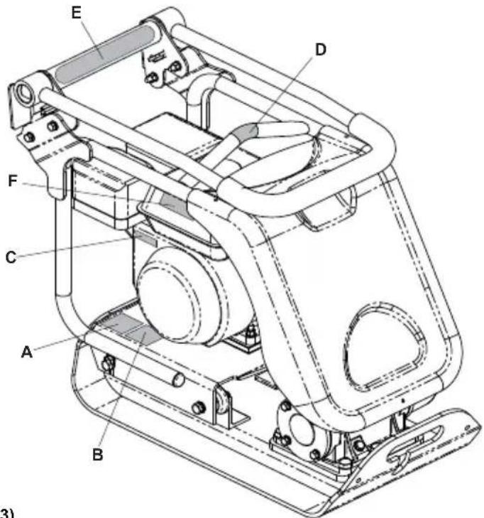
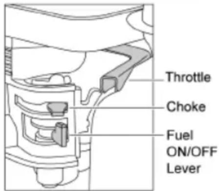
Technical diagram of a mechanical device with numbered parts, including exploded and assembled views- Throttle lever.
- Choke lever.
- Fuel ON / OFF lever.
- Engine ON / OFF switch.
- Air Filter Housing
- Fuel Tank.
- Exhaust.
- Recoil Starter Handle.
- Engine oil fi ller / dipstick.
- Engine oil drain plug.
- Vibrator.
- Vibrator oil check plug.
- Attachment point for Water Spray System or Paving Pad.
- Belt guard.
- Control Handle.
- Lifting Point.
- Attachment points for Transporter Options.
N.B. Drawing based a Honda GX160 engine. Please refer to the manufacturer's literature for Robin & Hatz engine details.
Environment

Safe Disposal.

Instructions for the protection of the environment. The machine contains valuable materials. Take the discarded apparatus and accessories to the relevant recycling facilities.
| Component | Material. | |
| Handle | Steel | |
| Front | cover | HDPE |
| Main | frame | Steel |
| Baseplate | Steel | |
| Hand | Grips | Rubber |
| Engine | Aluminium | |
| Flexible Mounts | Steel and Rubber | |
| Various Parts | Steel and Aluminium | |
| Water(if fitted) | Bottle | Plastic |

text_image
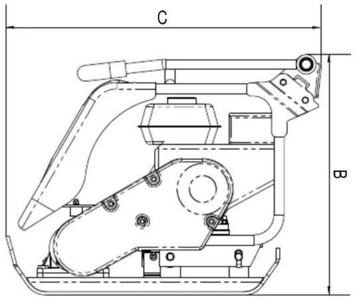
C B
natural_image
Technical line drawing of a mechanical component with labeled dimension A (no text or symbols beyond label)| Model | PCX350 | PCX400 | PCX450 | PCX500 | ||||
| A - Plate Width (mm) 350 400 450 500 | ||||||||
| B - Height - Petrol (mm) 610 610 610 610 | ||||||||
| B - Height - Diesel (mm) - 675 675 675 | ||||||||
| C - Length - Petrol (mm) 798 798 798 798 | ||||||||
| C - Length - Diesel (mm) 870 870 870 870 | ||||||||
| Weight Honda GX120 4.0hp/3kW (kg) 80 83 86 | 90 | |||||||
| Weight Honda GX160 5.5hp/4kW (kg) | - | - | - | 85 | ||||
| Weight Robin EX 13 4.5hp (kg) | 79 | 81 | 83 | 85 | ||||
| Weight Robin EX 17 6hp (kg) | 79 | 81 | 83 | 85 | ||||
| Weight Hatz Diesel 4.6hp/3.5kW (kg) | - | 105.5 | 110.5 | 115 | ||||
| Engine RPM - Honda / Robin | 3600 | 3600 | 3600 | 3600 | ||||
| Engine RPM - Hatz | 3600 | 3600 | 3600 | 3600 | ||||
| Vibrator Force (kN) | 14.5 | 16.5 | 16.5 | 16.5 | ||||
| Frequency (Hz) | 101 | 101 | 101 | 101 | ||||
| Max. Travel Speed - Petrol (m/min) | 18.5 | 18.5 | 18.5 | 18.5 | ||||
| Max. Travel Speed - Diesel (m/min) | - | 13.8 | 13.8 | 13.8 | ||||
| Static Pressure (kg/m2) | 451 | 405 | 368 | 340 | ||||
| Dual Force (NRSWA) Honda (kg/m2) | 2016 | 1808 | 1965 | 1812 | ||||
| Dual Force (NRSWA) Hatz (kg/m2) | - | 2087 | 2062 | 1895 | ||||
| Sound Power Level GX160, EX17 & Hatz | 107 (Lw(A)) | 107 (Lw(A)) | 107 (Lw(A)) | 107 (Lw(A)) | ||||
| Sound Power Level GX120, EX13 | 105 (Lw(A)) | 105 (Lw(A)) | 105 (Lw(A)) | 105 (Lw(A)) | ||||
| 3 Axis Vibration (m/sec2) | Honda Standard 2.26 | Honda HAUC 2.01 | Honda Standard 2.50 | Honda HAUC 2.25 | Honda Standard 2.45 | Honda HAUC 2.20 | Honda Standard 2.50 | Honda HAUC 2.25 |
| Usage Time (Hours) | 12.2 | 15.5 | 10 | 12.2 | 10.5 | 13 | 10 | 12.2 |
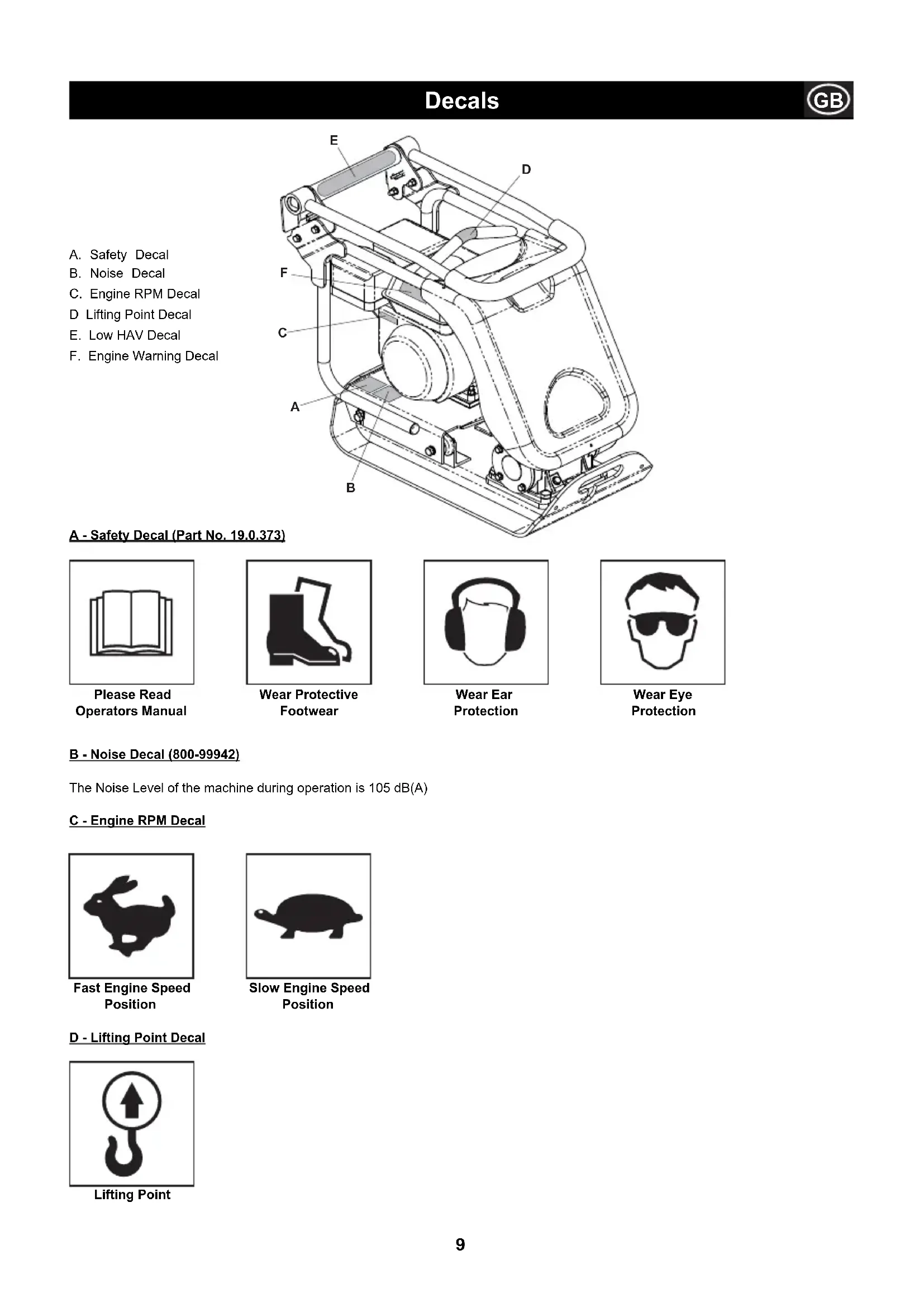
A. Safety Decal
B. Noise Decal
C. Engine RPM Decal
D Lifting Point Decal
E. Low HAV Decal
F. Engine Warning Decal

text_image
E D F C A B (3)A - Safety Decal (Part No. 19.0.373)

natural_image
Simple line drawing of an open book with no text or symbols visiblePlease Read Operators Manual
natural_image
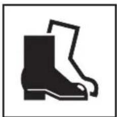
Silhouette of a boot with a pair of boots, no text or symbols presentWear Protective Footwear

natural_image
Simple line drawing of a person wearing headphones (no text or symbols)Wear Ear Protection

natural_image
Simple line drawing of a person's head wearing sunglasses (no text or symbols)Wear Eye Protection
B - Noise Decal (800-99942)
The Noise Level of the machine during operation is 105 dB(A)
C - Engine RPM Decal
natural_image
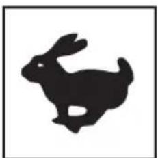
Silhouette of a rabbit in motion, no text or symbols presentFast Engine Speed Position

natural_image
Silhouette of a turtle (no text or symbols)Slow Engine Speed Position
D - Lifting Point Decal
natural_image
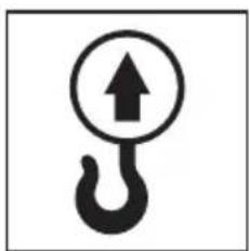
Symbol of a hook with an upward arrow inside, enclosed in a circle (no text or numbers present)Lifting Point
E - Low HAV Decal (800-99965)
The machine has a UK Patented Design which reduces HAV levels allowing a greater Usage Time.
F - Engine Warning Decal
text_image
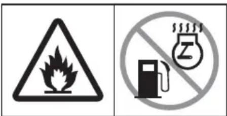
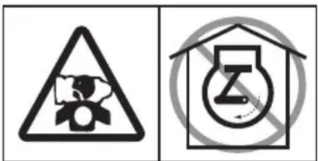
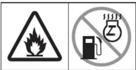
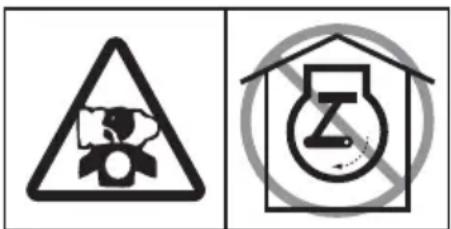
Two safety symbols: a triangular warning triangle with flame and a prohibition sign with a bottle and 'Z' symbol.Petrol is highly fl ammable. Turn off the Engine and allow time to cool before refuelling.
text_image
Two safety symbols: a triangular warning triangle with hazard symbol and a house with a circular symbol containing the letter 'Z'.The Engine emits toxic Carbon Monoxide. Do not run the Engine in an enclosed area.

natural_image
Simple line drawing of an open book with no text or symbols visiblePlease Read Engine Manual

General Safety
For your own personal protection and for the safety of those around you, please read and ensure you fully understand the following safety information. It is the responsibility of the operator to ensure that he/she fully understands how to operate this equipment safely. If you are unsure about the safe and correct use of the Plate Compactor, consult your supervisor or Belle Group.

CAUTION
Improper maintenance or use can be hazardous. Read and Understand this section before you perform any maintenance, service or repairs.
- This equipment is heavy and must not be lifted single-handedly, either GET HELP or use suitable lifting equipment. A special transport assembly is available for the compactor (see options).
• Cordon off the work area and keep members of the public and unauthorised personnel at a safe distance. - Personal Protective Equipment (PPE) must be worn by the operator whenever this equipment is being used (see Health & Safety).
• Make sure you know how to safely switch this machine OFF before you switch it ON in case you get into difficulty.
• Always switch OFF the engine before transporting, moving it around the site or servicing it. - During use the engine becomes very hot, allow the engine to cool before touching it. Never leave the engine running and unattended.
- Never remove or tamper with any guards fitted, they are there for your protection. Always check guards for condition and security, if any are damaged or missing, DO NOT USE THE COMPACTOR until the guard has been replaced or repaired.
- Do not operate the Compactor when you are ill, feeling tired, or when under the influence of alcohol or drugs.
Fuel Safety

CAUTION
Fuel is flammable. It may cause injury and property damage. Shut down the engine, extinguish all open flames and do not smoke while filling the fuel tank. Always wipe up any spilled fuel.
- Before refuelling, switch off the engine and allow it to cool.
- When refuelling, DO NOT smoke or allow naked flames in the area.
- Spilt fuel must be made safe immediately, using sand. If fuel is spilt on your clothes, change them.
- Store fuel in an approved, purpose made container away from heat and ignition sources.
Health and Safety
Vibration
Some vibration from the compaction operation is transmitted through the handle to the
operator's hands. The Belle Group Plate Compactor range has been specifically designed to reduce hand/arm vibration levels. Refer to specifications & technical data for vibration levels and usage times (recommended maximum daily exposure time). DO NOT exceed the maximum usage times.
PPE (Personal Protective Equipment).
Suitable PPE must be worn when using this equipment i.e. Safety Goggles, Gloves, Ear
Defenders, Dust Mask and Steel Toe capped footwear.
Wear clothing suitable for the work you are doing. Tie back long hair and remove any
jewellery which may catch in the equipment's moving parts.
Dust.
The compacting process will occasionally produce dust, which may be hazardous to your health. Always wear a mask that is suited to the type of dust being produced.
Fuel.
Do not ingest fuel or inhale fuel vapours and avoid contact with your skin. Wash fuel splashes immediately.
If you get fuel in your eyes, irrigate with copious amounts of water and seek medical attention as soon as possible.
Exhaust Fumes

CAUTION
The exhaust fumes produced by this equipment are highly toxic and can kill!
Do not operate the compactor indoors or in a confined space, make sure the work area is adequately ventilated.
Pre-Start Checks

Pre start-up inspection
The following Pre-start-up inspection must be performed before the start of each work session or after every four hours of use, whichever is first. Please refer to the service section for detailed guidance. If any fault is discovered, the compactor must not be used until the fault is rectified.
- Thoroughly inspect the compactor for signs of damage. Check components are present and secure. Pay special attention to the belt drive safety guard fitted between the engine and the vibrator unit.
- Check the engine oil level and top up as necessary.
- Check the engine fuel level and top up as necessary.
- Check for fuel and oil leaks.

CAUTION
Improper maintenance can be hazardous. Read and Understand this section before you perform any maintenance, service or repairs.
Honda GX120 & GX160
- Open the fuel tap by moving the fuel ON / OFF lever fully to the right.
- If starting the engine from cold, set the choke ON by moving the choke lever fully to the left. If restarting a warm engine, the choke is usually not required, however, if the engine has cooled to a degree, partial choke may be required.
- Turn the engine ON / OFF switch clockwise to the 'I' position.
- Set the throttle to the idle position by moving the throttle lever fully to the right. Do not start the engine on full throttle, as the compactor will vibrate as soon as the engine starts.
-
Taking a firm hold of the control handle with one hand, grasp the recoil starter handle with the other. Pull the recoil starter until engine resistance is felt, then let starter return.
-
Taking care not to pull the starter's rope fully out, pull the starter handle briskly.
-
Repeat until the engine fi res.
-
Once the engine fires gradually set the choke lever to the OFF position by moving it to the right.
-
If the engine fails to fire after several attempts, follow the trouble-shooting guide on page 8.
-
To stop the engine, set the throttle to idle and turn the engine ON / OFF switch anticlockwise to the '0' position.
-
Turn the fuel off.
text_image
Throttle Choke Fuel ON/OFF LeverRobin EX13 & EX17 Petrol Engine
- Open the fuel cock.
- Turn the STOP SWITCH to the position 'I' (ON)
- Set the speed control lever 1/3 of the way towards the high speed position.
- Close the choke lever.
- If the engine is cold or the ambient temperature is low, close the choke lever fully.
-
If the engine is warm or the ambient temperature is high, open the choke lever half way, or keep it fully open.
-
Pull the starter handle slowly until resistance is felt. This is the 'compression' point, return the handle to its original position and pull swiftly. Do not pull out the rope all the way. After starting the engine, allow the starter handle to return to its original position while still holding the handle.
-
After starting the engine, gradually open the choke by turning the choke lever and finally keep it fully opened. Do not fully open the choke lever immediately when the engine is cold or the ambient temperature is low, because the engine may stop.
-
To stop the engine, Set the speed control lever at the low speed position and allow the engine to run at low speed for 1 to 2 minutes before stopping.
-
Turn the STOP SWITCH counter-clockwise to the position '0' (OFF)
-
Close the fuel cock.
-
Pull the starter handle slowly and return the handle to its original position when resistance is felt. This operation is necessary to prevent outside moist air from intruding into the combustion chamber.
Hatz 1B20-7 Diesel Engine (please refer to the engine manual for full details)
- Turn ON the fuel by moving the fuel ON/OFF lever fully to the right.
- Set the engine speed control to start.
- Taking a firm hold of the control handle with one hand, grasp the recoil starter handle with the other. Pull the handle until engine resistance is felt, then let the starter return.
- Taking care not to pull the starter's rope fully out, pull the starter handle briskly with both hands.
- Repeat this procedure until the engine fi res.
- If the engine fails to start after several attempts, consult the engine manual supplied with the compactor.
- To stop the engine, set the throttle control to idle, then press and hold the red stop button until the engine stops.

Reasons For Compaction
Soil, which has been disturbed or new infill, subbase and blacktop, will have small voids or air pockets which, if not compacted, will lead to one or more problems occurring.
- As traffic crosses the surface of an uncompacted area, the material is compressed. This leads to subsidence of the top surface as the material fills the voids.
- A similar situation occurs with static loads on uncompacted ground. The load (e.g. a building) will sink.
- Materials with voids are more susceptible to water seepage, leading to erosion. Water ingress may also cause the soil to expand during freezing temperatures and contract during dry spells. Expansion and contraction is a major cause of damage to building foundations and normally leads to the structure requiring underpinning. Compaction increases the density of the material and therefore increases its load bearing capacity. Reduces air voids and therefore reduces the risk of subsidence, expansion and contraction, due to ingress of water.
Operating The Compactor
• Take the compactor to where it is required.
If using the 'Detachable' transport attachment to wheel the unit, tilt the compactor forward to raise the transport wheels off the ground. Swing the transporter frame back, then across to disconnect it from the rear of the compactor. Place the transporter frame somewhere safe until next required. For machines with the 'Fixed' transporter tilt the machine forward, pull the transporter rearwards and upwards, lower the machine to the floor and latch the transporter into the 'up' position.
Where it is necessary to use lifting equipment to position the compactor, make sure the lifting equipment has a WLL (Working Load Limit) suitable for the compactors weight (see specification chart on page 4 or the machine numberplate). Attach suitable chains or slings ONLY to the lifting point on the top of the compactor.
- If the compactor is fitted with the water spray system and the application requires its use, check that the water outlet valve is closed, then fi ll the water bottle with clean water.
- Having carried out the checks listed in the 'pre start' section, you may start the engine.
The Belle Group 'PCx' range of compactors are fitted with a centrifugal clutch, this allows the engine to run at idle without driving the vibrator.
As the engine speed is increased the clutch will engage and will drive the vibrator.
For correct operation, the engine speed should be set to maximum.
- Set the throttle to maximum and use the control handle to steer or turn the compactor.
The vibrator will not only cause the baseplate to vibrate but will also cause it to travel forward. During normal operation you should not have to push the compactor but allow it to travel at its own pace. The speed of travel will be determined by the condition of the surface being compacted.
If the surface to be compacted is on a slope, great care must be taken when controlling the compactor's direction of travel. If necessary, use a suitable rope attached to the compactor at a low point on the chassis, to allow a helper to take part of the compactor's weight. Work up and down a slope not across.
• Work the compactor over the surface in an organised pattern until the required compaction has been achieved.
Where there are a number of different layers to be compacted on top of each other, compact each layer individually.
• To stop the compactor vibrating, set the throttle to idle.
Applications

Applications/materials fall into three categories:
- Cohesive materials (less than 20% granular) e.g clay, silt & heavy soils.
- Granular materials (more than 20% granular) e.g hard core, sand & light soils.
- Bituminous materials e.g asphalt (tarmac), cold lay (bitumin emulsion products).
The chart shows the HAUC specifications for layer depth and number of passes for Dual Force' plates. If standard machines are used, optimum compaction can not be guaranteed, however, if layer depths are reduced and number of passes increased, results can be improved.
Moisture content of cohesive & granular materials is critical to effective compaction. If granular material is too dry it will flow around the plate instead of compacting. If the moisture content is too high the material may dry out after compaction and shrinkage will occur.
| 1400 -1800 kg/m2 | COMPACTION PASSESS REQUIRED PER LAYER OF COMPACTED THICKNESS UP TO. | ||||||
| 40MM | 60MM | 80MM | 100MM | 150MM | |||
| Cohesive Materials** | 2** | 4** | 5** | 6** | |||
| Granular Materials | 2* | 3* | 4* | 5 | |||
| Bituminous | 6 | 10 | 12 | ||||
* Usually placed in 100mm minimum layer so not specified by HAUC.
** The nature of cohesive materials makes plate compaction difficult. Optimum compaction is not guaranteed and not recommended by HAUC.
Various methods have been employed in the past to specify the compaction required for various applications. The factors to consider are, material properties, layer thickness, pressure applied, vibration and number of passess. Greater understanding of how compaction works has lead to new compaction specifications being introduced.
The most up to date specification is part of the U.K.'s NRSWA (New Roads & Street Works Act). Civil Engineers are now adopting these specifications to ensure good compaction for all site work.
NRSWA (HAUC specifi cation).
The specification was compiled by HAUC (Highways Authorities & Utilities Committee).
The ‘New Roads and Street Works Act 1991, set a new standard for road repairs and reinstatements in the UK. It covers materials, methods, equipment and safety when carrying out reinstatements on roads and footways.
The reason for the act is to ensure repairs and reinstatements are carried out to a higher standard and ultimately last longer. This in turn will reduce the need for costly remedial work and reduce traffic delays.
There are two categories specified for plate compactors.
- 1400 to 1800kg/m² 2. Over 1800kg/m²
These figures relate to the static pressure applied by the machine
NOTE: No standard single direction plate compactors comply with this minimum specification. For highways work always use a 'Dual Force' plate compactor.
DUAL FORCE
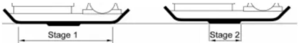
Belle Group studied the act then developed and patented equipment to enable contractors to comply with the act's requirements. The NRSWA legislation requires that compaction equipment meets the minimum specification. By purchasing an Belle Group 'Dual Force' plate, you are immediately complying with this part of the act. To comply with the specification and maintain surface tolerance, Belle Group 'Dual Force' base plates are divided into two areas providing two stages of compaction.
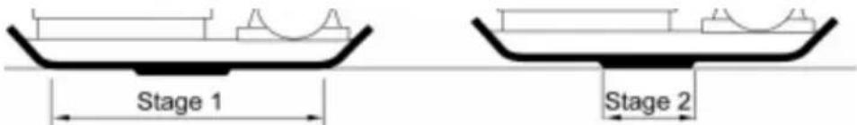
text_image
Stage 1 Stage 2Stage 1: The full base area compacts the material like a standard machine.
Stage 2: The base rises onto the 'Dual Force' section to give 3 to 4 times the compaction force of standard plates.

Troubleshooting Guide
| Problem Cause Remedy | ||
| Engine will not start. No fuel. | Open fuel tap. | |
| Fill fuel tank. | ||
| Engine switched off. | Switch engine on. | |
| Spark plug fouled. | Clean and reset plug gap. | |
| cold. | Close choke. | |
| Engine flooded. | Honda, open choke, fully open throttle, pull recoil starter until engine fires. | |
| Hatz, move speed control to stop, pull recoil starter 5 times then repeat start procedure. | ||
| Engine still will not start. | Major Fault | Contact Agent or Belle Group. |
| Unit will not vibrate. | Engine speed too slow. | Set engine speed control to fast. |
| Drive belt tension loose. | Adjust belt tension. | |
| Air filter blocked. | Clean or renew air filter. | |
| Drive failure. | Contact Agent or Belle Group. | |
| Vibrator failure. | Contact Agent or Belle Group. | |
| Asphalt adhering to plate. | Lack of lubrication. | Use a water spray system. |
| Paving blocks damaged. | Plate in direct contact with material. | Use a paving pad. |
| Standard pad used on Dual Force plate. | Fit correct Dual Force Pad | |
| Bituminous surface flaking (laminating). | Over compaction. | Remove and relay. |
| Low travel speed (plate sinking). | Layer thickness too deep. | Remove some of the material. |
| Moisture content too high or too low. | Remove material and adjust. |
Maintenance
The Belle Group 'PCX' range of Single Direction Plate Compactors are designed to give many years of trouble free operation. It is, however, important that the simple regular maintenance listed in this section is carried out.
It is recommended that an approved Belle Group dealer carries out all major maintenance and repairs. Always use genuine Belle Group replacement parts, the use of spurious parts may void your warranty.
Before any maintenance is carried out on the machine, switch off the engine. If working on a petrol engined machine, disconnect the HT lead from the sparkplug. If working on a diesel engine, make sure that the stop switch is in the stop position. Always set the compactor on level ground to ensure any fluid levels will be correctly read. Only use recommended oils (see chart on following page).
Running In Period
When the compactor is first used from new, the engine oil must be changed after the initial running in period (see engine manual for full detail). The vibrator shaft case oil must be replaced after the first 100 hours use, then after every 500 working hours. For detail on vibrator shaft case oil replacement, see 'Vibrator unit'. The belt tension should be checked after 4 hours use.
Drive Belt
Remove the belt guard then check the belt tension by placing light finger pressure on the top of the belt, as near central between the engine drive and vibrator pulley. The belt should deflect by between 5mm and 10mm. If the belt tension requires adjustment, loosen the four engine mount bolts enough to allow the engine to be moved. Adjust the engine's position by turning the tension bolt clockwise to increase belt tension, anti-clockwise to decrease. Once set, retighten the engine mount bolts and check the belt tension a second time. Finally, replace the belt guard ensuring it is correctly and securely fitted.
| Routine Maintenance First 4 First month / 3 Months 6 months hours 20Hours 50 Hours 100 Hours | |||||
| Engine Oil | Check Level | √ | |||
| Change | √ | √ | |||
| Air Filter | Check Condition/Clean | √ | √ | ||
| Replace when necessary / Every 12 months | |||||
| Spark Plug | Change | √ | |||
| Drive Belt | Tension | √ | √ | √ | |
Oil / Fuel Type & Quantity - Spark Plug Type
| Oil type | Quantity (Litre) | Fuel Type | Capacity (Litre) | Spark Plug Type | Electrode Gap (mm) | |
| Petrol Honda GX120 | S.A.E. 10W 30 | 0.6 | Unleaded | 2.5 | BM6ES or BPR6ES | 0.7 - 0.8 |
| Petrol Honda GX160 | S.A.E. 10W 30 | 0.6 | Unleaded | 3.6 | BM6ES or BPR6ES | 0.6 - 0.7 |
| Petrol Robin EX13 | S.A.E. 10W 30 | 0.6 | Unleaded | 2.7 | NGK BR-6HS | |
| Petrol Robin EX17 | S.A.E. 10W 30 | 1.1 | Unleaded | 3.6 | NGK BR-6HS | |
| Diesel Hatz 1B20-6 | S.A.E. 10W 30 | 0.9 | Diesel (BS2869) | Refer to Manual | N/A | N/A |
| Vibrator | Turbine Oil 32 | 0.4 | N/A | N/A | N/A | N/A |

text_image
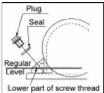
Plug Seal Regular Level Lower part of screw threadVibrator Unit.
Remove the plug complete with seal, check that the oil level reaches the bottom thread on the oil plug hole. Top up as necessary with the correct oil (see chart).
Assembly Instructions for Vibrator
- Clean out Housing (9) with gun wash then blow dry with compressed air.
- Fit rear Bearing (3a) into Housing and push Shaft (8) into Bearing.
- Fit front Bearing (3b) onto Shaft and into Housing.
- Fit Bearing Cover 'B' (10) c/w Gasket (4a) to the rear of the Housing.
- Fit Oil Seal (6) into Bearing Cover 'A' (7).
- Fit Bearing Cover 'A' c/w Gasket (4b) to the front of the Housing.
- Fit Woodruff Key (11) and Pulley (12) onto Shaft.
- Pour oil into oil drain hole in the housing until oil just starts to trickle out.
- Fit Copper Washer (2) and Oil Drain Plug (1).
- Fit Vibrator onto Baseplate and tighten bolts to a torque of 150Nm.
- Run for approximately 2 minutes to ensure oil does not leak from the Vibrator.

text_image
Exploded view diagram of a mechanical assembly with numbered parts for identification
Fitting Instructions
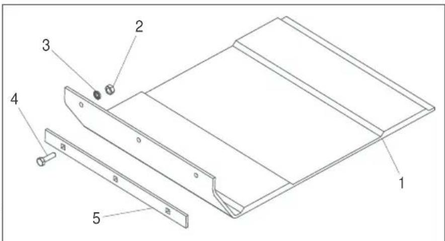
Paving Pad
The paving pad has been designed to be used when tamping down paving slabs and block pavers. However, it should not be used for normal compaction work.
Before fi tting, make sure the paving pad you have is the correct size and the correct type (HAUC 'Dual Force' or standard).
To fit the Paving Pad (1), place the pad under the plate ensuring the securing holes line up with the holes on the front of the baseplate.
The securing coach bolts (4) should be passed through the clamp strip (5) then the paving pad (1) and finally through the baseplate. They are in turn secured in place with the nut (2) and washer (3).
text_image
Technical diagram of a mechanical assembly with numbered components labeled 1 to 5Transporter Attachment
The transporter attachment enables the operator to move the compactor to the work place with the minimum of effort.
Removable Transporter Attachment
To fit the transport attachment, align the pivot bracket with the holes on the rear of the baseplate.
The two securing bolts should be passed through the pivot bracket and the baseplate. They are in turn secured in place with the Nyloc nut and washer.
Slide the wheel frame onto the pivot bracket, tilt the compactor forward then swing the wheel frame forward and under. Finally, tilt the compactor back and onto the wheels.
Fixed Transporter Attachment
To fit the transport attachment, align the bracket with the holes on the rear of the bedplate. The two securing bolts should be passed through the bracket and into the bedplate.

This machine is fitted with a 'Dual Force' base plate.

This machine is not fitted with a 'Dual Force' base plate.
When fitted with a 'Dual Force' base plate the Static Weight per Unit Area of this machine is over 1400 kg/m^2 and so complies with the NRSWA (HAUC specification) for plate compactors in the category 1400 - 1800 kg/m^2 .
Managing
Director

R.
Neilson
'Dual Force' allows Belle Group plate compactors to be used for Highways reinstatements in accordance with the specifications stated in the NRSWA (New Roads and Streetworks Act 1991) Appendix A8.
'Dual Force' is only available on Belle Group plate compactors. The design is protected worldwide and in the UK by Patent (No. 2261840). Standard Belle Group plate compactors can be retro fitted with 'Dual Force', contact Belle Group for details.
Warranty

Your new Belle Group ‘PCX’ single direction plate compactor is warranted to the original purchaser for a period of one-year (12 months) from the original date of purchase.
The Belle Group warranty is against defects in design, materials and workmanship.
The following are not covered under the Belle Group warranty:
- Damage caused by abuse, misuse, dropping or other similar damage caused by or as a result of failure to follow assembly, operation or user maintenance instructions.
- Alterations, additions or repairs carried out by persons other than Belle Group or their recognised agents.
- Transportation or shipment costs to and from Belle Group or their recognised agents, for repair or assessment against a warranty claim, on any machine.
- Materials and/or labour costs to renew, repair or replace components due to fair wear and tear.
The following components are not covered by warranty.
- Drivebelt/s
· Engine air filter
· Engine spark plug
Belle Group and/or their recognised agents, directors, employees or insurers will
not be held liable for consequential or other damages, losses or expenses in
connection with or by reason of or the inability to use the machine for any purpose.
Warranty Claims
All warranty claims should firstly be directed to Belle Group, either by telephone, by Fax, by Email, or in writing.
For warranty claims:
Tel: +44 (0)1538 380000 Fax: +44 (0)1538 380038
Email : Warranty@belle-group.co.uk
Write to:
Belle Group Warranty Department,
Unit 5, Bode Business Park,
Ball Haye Green,
Leek,
Staffordshire ST13 6BW
England.
This manual has been written to help you operate and service the Plate Compactor safely. This manual is intended for dealers and operators of the Plate Compactor.
Foreword
The ‘Environment’ section gives instructions on how to handle the recycling of discarded apparatus in an environmentally friendly way.
The ‘Machine Description’ section helps you to familiarise yourself with the machine's layout and controls.
The ‘General Safety’ and ‘Health and Safety’ sections explain how to use the machine to ensure your safety and the safety of the general public.
The 'Start and Stop Procedure' helps you with starting and stopping the machine.
The ‘Trouble Shooting’ guide helps you if you have a problem with your machine.
The ‘Servicing’ section is to help you with the general maintenance and servicing of your machine.
The ‘ Warranty’ Section details the nature of the warranty cover and the claims procedure.
The ‘ Dual Force’ section shows the compaction specification the machine can achieve.
The 'CE certificate' section shows the standards that the machine has been built to.
Directives with regard to the notations.
Text in this manual to which special attention must be paid are shown in the following way:

CAUTION
The product can be at risk. The machine or yourself can be damaged or injured if procedures are not carried out in the correct way.

WARNING
The life of the operator can be at risk.

WARNING

WARNING
Before you operate or carry out any maintenance on this machine YOU MUST READ and STUDY this manual.
KNOW how to safely use the unit's controls and what you must do for safe maintenance. (NB Be sure that you know how to switch the machine off before you switch on, in case you get into difficulty.)
ALWAYS wear or use the proper safety items required for your personal protection. If you have ANY QUESTIONS about the safe use or maintenance of this unit, ASK YOUR SUPERVISOR OR CONTACT: BELLE GROUP (UK): +44 (0) 1298 84606

Contents
How to use this manual ....18
Warning 18
Machine Description ....19
Environment 19
Technical Data 20
Decals....21 - 22
General Safety 22
Health and Safety 23
Pre-Start Safety Checks 23
Start & Stop Procedure 24
Reasons for Compaction 24
Operating the Compactor 25
Applications 25
Compaction Specification 26
Trouble Shooting Guide ....26
Servicing 27
Assembly Instructions ......28
Fitting Instructions....28
Dual Force Certificate 29
Warranty 29

text_image
Technical diagram of a mechanical device with numbered parts, including exploded and assembled views- Throttle lever.
- Choke lever.
- Fuel ON / OFF lever.
- Engine ON / OFF switch.
- Air Filter Housing
- Fuel Tank.
- Exhaust.
- Recoil Starter Handle.
- Engine oil fi ller / dipstick.
- Engine oil drain plug.
- Vibrator.
- Vibrator oil check plug.
- Attachment point for Water Spray System or Paving Pad.
- Belt guard.
- Control Handle.
- Lifting Point.
- Attachment points for Transporter Options.
N.B. Drawing based a Honda GX160 engine. Please refer to the manufacturer's literature for Robin & Hatz engine details.
Environment

Safe Disposal.

Instructions for the protection of the environment. The machine contains valuable materials. Take the discarded apparatus and accessories to the relevant recycling facilities.
| Component | Material. | |
| Handle | Steel | |
| Front | cover | HDPE |
| Main | frame | Steel |
| Baseplate | Steel | |
| Hand | Grips | Rubber |
| Engine | Aluminium | |
| Flexible Mounts | Steel and Rubber | |
| Various Parts | Steel and Aluminium | |
| Water(if fitted) | Bottle | Plastic |
text_image
C B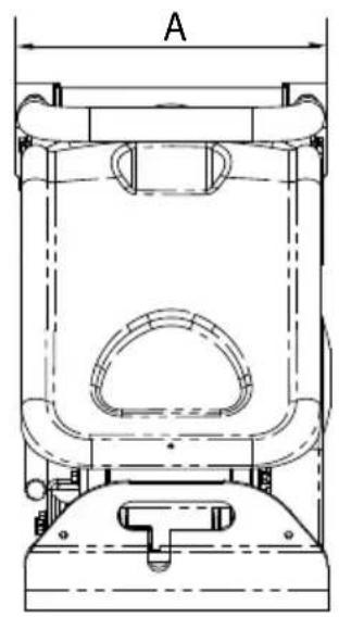
natural_image
Technical line drawing of a mechanical component with labeled dimension A (no text or symbols beyond label)| Model | PCX350 | PCX400 | PCX450 | PCX500 | ||||
| A - Plate Width (In) 13.7 15.7 17.7 19.7 | ||||||||
| B - Height - Gasoline (In) 24 24 24 24 | ||||||||
| B - Height - Diesel (In) - 26.5 26.5 26.5 | ||||||||
| C - Length - Gasoline (In) 31.4 31.4 31.4 | 31.4 | |||||||
| C - Length - Diesel (In) 34.2 34.2 34.2 34.2 | 2 | |||||||
| Weight Honda GX120 4.0hp/3kW (lbs) 174 | 178 183 | 187 | ||||||
| Weight Honda GX160 5.5hp/4kW (lbs) | - | - | - | 187 | ||||
| Weight Robin EX 13 4.5hp (lbs) | 174 | 178 | 183 | 187 | ||||
| Weight Robin EX 17 6hp (lbs) | 174 | 178 | 183 | 187 | ||||
| Weight Hatz Diesel 4.6hp/3.5kW (lbs) | - | 207 | 212 | 216 | ||||
| Engine RPM - Honda / Robin | 3600 | 3600 | 3600 | 3600 | ||||
| Engine RPM - Hatz | 3600 | 3600 | 3600 | 3600 | ||||
| Vibrator Force (lbf) | 3260 | 3709 | 3709 | 3709 | ||||
| Frequency (Hz) | 101 | 101 | 101 | 101 | ||||
| Max. Travel Speed - Gasoline (ft/min) | 78.7 78.7 78.7 75.4 | |||||||
| Max. Travel Speed - Diesel (ft/min) | - | 69 | 69 | 65.6 | ||||
| Static Pressure (Ibs/ft ^2 ) | 92.3 | 82.9 | 75.3 | 69.6 | ||||
| Dual Force (NRSWA) Honda (Ibs/ft ^2 ) | 412.9 | 370.3 | 402.4 | 371.1 | ||||
| Dual Force (NRSWA) Hatz (Ibs/ft ^2 ) | - | 427.4 | 422.3 | 380.1 | ||||
| Sound Power Level GX160, EX17 & Hatz | 107 (Lw(A)) | 107 (Lw(A)) | 107 (Lw(A)) | 107 (Lw(A)) | ||||
| Sound Power Level GX120, EX13 | 105 (Lw(A)) | 105 (Lw(A)) | 105 (Lw(A)) | 105 (Lw(A)) | ||||
| 3 Axis Vibration (ft/sec ^2 ) | Honda Standard 7.41 | Honda HAUC 6.59 | Honda Standard 8.20 | Honda HAUC 7.38 | Honda Standard 8.03 | Honda HAUC 7.21 | Honda Standard 8.20 | Honda HAUC 7.38 |
| Usage Time (Hours) | 12.2 | 15.5 | 10 | 12.2 | 10.5 | 13 | 10 | 12.2 |
A. Safety Decal
B. Noise Decal
C. Engine RPM Decal
D Lifting Point Decal
E. Low HAV Decal
F. Engine Warning Decal
text_image
E D F C A B (3)A - Safety Decal (Part No. 19.0.373)

natural_image
Simple line drawing of an open book with no text or symbols visiblePlease Read Operators Manual

natural_image
Silhouette of a boot with a pair of boots, no text or symbols presentWear Protective Footwear

natural_image
Simple line drawing of a person wearing headphones (no text or symbols)Wear Ear Protection

natural_image
Simple line drawing of a person's head wearing sunglasses (no text or symbols)Wear Eye Protection
B - Noise Decal (800-99942)
The Noise Level of the machine during operation is 105 dB(A)
C - Engine RPM Decal

natural_image
Silhouette of a rabbit in motion, no text or symbols presentFast Engine Speed Position

natural_image
Silhouette of a turtle (no text or symbols)Slow Engine Speed Position
D - Lifting Point Decal

natural_image
Symbol of a hook with an upward arrow inside a circle (no text or numbers present)Lifting Point
E - Low HAV Decal (800-99965)
The machine has a UK Patented Design which reduces HAV levels allowing a greater Usage Time.
F - Engine Warning Decal
text_image
Two safety symbols: a triangular warning triangle with flame and a prohibition sign with a bottle and 'Z' symbol.Petrol is highly fl ammable. Turn off the Engine and allow time to cool before refuelling.
text_image
Two safety symbols: a triangular warning triangle with hazard symbol and a house-shaped icon with 'Z' and a circular symbol.The Engine emits toxic Carbon Monoxide. Do not run the Engine in an enclosed area.

natural_image
Simple line drawing of an open book with no text or symbols visiblePlease Read Engine Manual

General Safety
For your own personal protection and for the safety of those around you, please read and ensure you fully understand the following safety information. It is the responsibility of the operator to ensure that he/she fully understands how to operate this equipment safely. If you are unsure about the safe and correct use of the Plate Compactor, consult your supervisor or Belle Group.

CAUTION
Improper maintenance or use can be hazardous. Read and Understand this section before you perform any maintenance, service or repairs.
- This equipment is heavy and must not be lifted single-handedly, either GET HELP or use suitable lifting equipment. A special transport assembly is available for the compactor (see options).
• Cordon off the work area and keep members of the public and unauthorised personnel at a safe distance. - Personal Protective Equipment (PPE) must be worn by the operator whenever this equipment is being used (see Health & Safety).
• Make sure you know how to safely switch this machine OFF before you switch it ON in case you get into difficulty.
• Always switch OFF the engine before transporting, moving it around the site or servicing it. - During use the engine becomes very hot, allow the engine to cool before touching it. Never leave the engine running and unattended.
- Never remove or tamper with any guards fitted, they are there for your protection. Always check guards for condition and security, if any are damaged or missing, DO NOT USE THE COMPACTOR until the guard has been replaced or repaired.
- Do not operate the Compactor when you are ill, feeling tired, or when under the influence of alcohol or drugs.
Fuel Safety

CAUTION
Fuel is flammable. It may cause injury and property damage. Shut down the engine, extinguish all open flames and do not smoke while filling the fuel tank. Always wipe up any spilled fuel.
- Before refuelling, switch off the engine and allow it to cool.
- When refuelling, DO NOT smoke or allow naked flames in the area.
- Spilt fuel must be made safe immediately, using sand. If fuel is spilt on your clothes, change them.
- Store fuel in an approved, purpose made container away from heat and ignition sources.
Health and Safety
Vibration
Some vibration from the compaction operation is transmitted through the handle to the operator's hands. The Belle Group Plate Compactor range has been specifically designed to reduce hand/arm vibration levels. Refer to specifications & technical data for vibration levels and usage times (recommended maximum daily exposure time). DO NOT exceed the maximum usage times.
PPE (Personal Protective Equipment).
Suitable PPE must be worn when using this equipment i.e. Safety Goggles, Gloves, Ear Defenders, Dust Mask and Steel Toe capped footwear. Wear clothing suitable for the work you are doing. Tie back long hair and remove any jewellery which may catch in the equipment's moving parts.
Dust.
The compacting process will occasionally produce dust, which may be hazardous to your health. Always wear a mask that is suited to the type of dust being produced.
Fuel.
Do not ingest fuel or inhale fuel vapours and avoid contact with your skin. Wash fuel splashes immediately. If you get fuel in your eyes, irrigate with copious amounts of water and seek medical attention as soon as possible.
Exhaust Fumes

CAUTION
The exhaust fumes produced by this equipment are highly toxic and can kill!
Do not operate the compactor indoors or in a confined space, make sure the work area is adequately ventilated.
Pre-Start Checks

Pre start-up inspection
The following Pre-start-up inspection must be performed before the start of each work session or after every four hours of use, whichever is first. Please refer to the service section for detailed guidance. If any fault is discovered, the compactor must not be used until the fault is rectified.
- Thoroughly inspect the compactor for signs of damage. Check components are present and secure. Pay special attention to the belt drive safety guard fitted between the engine and the vibrator unit.
- Check the engine oil level and top up as necessary.
- Check the engine fuel level and top up as necessary.
- Check for fuel and oil leaks.

CAUTION
Improper maintenance can be hazardous. Read and Understand this section before you perform any maintenance, service or repairs.
Honda GX120 & GX160
- Open the fuel tap by moving the fuel ON / OFF lever fully to the right.
- If starting the engine from cold, set the choke ON by moving the choke lever fully to the left. If restarting a warm engine, the choke is usually not required, however, if the engine has cooled to a degree, partial choke may be required.
- Turn the engine ON / OFF switch clockwise to the 'I' position.
- Set the throttle to the idle position by moving the throttle lever fully to the right. Do not start the engine on full throttle, as the compactor will vibrate as soon as the engine starts.
-
Taking a firm hold of the control handle with one hand, grasp the recoil starter handle with the other. Pull the recoil starter until engine resistance is felt, then let starter return.
-
Taking care not to pull the starter's rope fully out, pull the starter handle briskly.
-
Repeat until the engine fi res.
-
Once the engine fires gradually set the choke lever to the OFF position by moving it to the right.
-
If the engine fails to fire after several attempts, follow the trouble-shooting guide on page 18.
-
To stop the engine, set the throttle to idle and turn the engine ON / OFF switch anticlockwise to the '0' position.
-
Turn the fuel off.
text_image
Throttle Choke Fuel ON/OFF LeverRobin EX13 & EX17 Petrol Engine
- Open the fuel cock.
- Turn the STOP SWITCH to the position 'I' (ON)
- Set the speed control lever 1/3 of the way towards the high speed position.
- Close the choke lever.
- If the engine is cold or the ambient temperature is low, close the choke lever fully.
-
If the engine is warm or the ambient temperature is high, open the choke lever half way, or keep it fully open.
-
Pull the starter handle slowly until resistance is felt. This is the 'compression' point. return the handle to its original position and pull swiftly. Do not pull out the rope all the way. After starting the engine, allow the starter handle to return to its original position while still holding the handle.
-
After starting the engine, gradually open the choke by turning the choke lever and finally keep it fully opened. Do not fully open the choke lever immediately when the engine is cold or the ambient temperature is low, because the engine may stop.
-
To stop the engine, Set the speed control lever at the low speed position and allow the engine to run at low speed for 1 to 2 minutes before stopping.
-
Turn the STOP SWITCH counter-clockwise to the position '0' (OFF)
-
Close the fuel cock.
-
Pull the starter handle slowly and return the handle to its original position when resistance is felt. This operation is necessary to prevent outside moist air from intruding into the combustion chamber.
Hatz 1B20-7 Diesel Engine (please refer to the engine manual for full details)
- Turn ON the fuel by moving the fuel ON/OFF lever fully to the right.
- Set the engine speed control to start.
- Taking a firm hold of the control handle with one hand, grasp the recoil starter handle with the other. Pull the handle until engine resistance is felt, then let the starter return.
- Taking care not to pull the starter's rope fully out, pull the starter handle briskly with both hands.
- Repeat this procedure until the engine fi res.
- If the engine fails to start after several attempts, consult the engine manual supplied with the compactor.
- To stop the engine, set the throttle control to idle, then press and hold the red stop button until the engine stops.

Reasons For Compaction
Soil, which has been disturbed or new infill, subbase and blacktop, will have small voids or air pockets which, if not compacted, will lead to one or more problems occurring.
- As traffic crosses the surface of an uncompacted area, the material is compressed. This leads to subsidence of the top surface as the material fills the voids.
- A similar situation occurs with static loads on uncompacted ground. The load (e.g. a building) will sink.
- Materials with voids are more susceptible to water seepage, leading to erosion. Water ingress may also cause the soil to expand during freezing temperatures and contract during dry spells. Expansion and contraction is a major cause of damage to building foundations and normally leads to the structure requiring underpinning.
Compaction increases the density of the material and therefore increases its load bearing capacity. Reduces air voids and therefore reduces the risk of subsidence, expansion and contraction, due to ingress of water.
Operating The Compactor
• Take the compactor to where it is required.
If using the 'Detachable' transport attachment to wheel the unit, tilt the compactor forward to raise the transport wheels off the ground. Swing the transporter frame back, then across to disconnect it from the rear of the compactor. Place the transporter frame somewhere safe until next required. For machines with the 'Fixed' transporter tilt the machine forward, pull the transporter rearwards and upwards, lower the machine to the floor and latch the transporter into the 'up' position.
Where it is necessary to use lifting equipment to position the compactor, make sure the lifting equipment has a WLL (Working Load Limit) suitable for the compactors weight (see specification chart on page 4 or the machine numberplate). Attach suitable chains or slings ONLY to the lifting point on the top of the compactor.
- If the compactor is fitted with the water spray system and the application requires its use, check that the water outlet valve is closed, then fi ll the water bottle with clean water.
- Having carried out the checks listed in the 'pre start' section, you may start the engine.
The Belle Group 'PCx' range of compactors are fitted with a centrifugal clutch, this allows the engine to run at idle without driving the vibrator.
As the engine speed is increased the clutch will engage and will drive the vibrator.
For correct operation, the engine speed should be set to maximum.
- Set the throttle to maximum and use the control handle to steer or turn the compactor.
The vibrator will not only cause the baseplate to vibrate but will also cause it to travel forward. During normal operation you should not have to push the compactor but allow it to travel at its own pace. The speed of travel will be determined by the condition of the surface being compacted.
If the surface to be compacted is on a slope, great care must be taken when controlling the compactor's direction of travel. If necessary, use a suitable rope attached to the compactor at a low point on the chassis, to allow a helper to take part of the compactor's weight. Work up and down a slope not across.
• Work the compactor over the surface in an organised pattern until the required compaction has been achieved.
Where there are a number of different layers to be compacted on top of each other, compact each layer individually.
• To stop the compactor vibrating, set the throttle to idle.
Applications

Applications/materials fall into three categories:
- Cohesive materials (less than 20% granular) e.g clay, silt & heavy soils.
- Granular materials (more than 20% granular) e.g hard core, sand & light soils.
- Bituminous materials e.g asphalt (tarmac), cold lay (bitumin emulsion products).
The chart shows the HAUC specifications for layer depth and number of passes for Dual Force' plates. If standard machines are used, optimum compaction can not be guaranteed, however, if layer depths are reduced and number of passes increased, results can be improved.
Moisture content of cohesive & granular materials is critical to effective compaction. If granular material is too dry it will flow around the plate instead of compacting. If the moisture content is too high the material may dry out after compaction and shrinkage will occur.
| 1400 -1800 kg/m2 | COMPACTION PASSESS REQUIRED PER LAYER OF COMPACTED THICKNESS UP TO. | ||||||
| 40MM | 60MM | 80MM | 100MM | 150MM | |||
| Cohesive Materials** | 2** | 4** | 5** | 6** | |||
| Granular Materials | 2* | 3* | 4* | 5 | |||
| Bituminous | 6 | 10 | 12 | ||||
* Usually placed in 100mm minimum layer so not specified by HAUC.
** The nature of cohesive materials makes plate compaction difficult. Optimum compaction is not guaranteed and not recommended by HAUC.
Compaction Specification
Various methods have been employed in the past to specify the compaction required for various applications. The factors to consider are, material properties, layer thickness, pressure applied, vibration and number of passess. Greater understanding of how compaction works has lead to new compaction specifications being introduced.
The most up to date specification is part of the U.K.'s NRSWA (New Roads & Street Works Act). Civil Engineers are now adopting these specifications to ensure good compaction for all site work.
NRSWA (HAUC specifi cation).
The specification was compiled by HAUC (Highways Authorities & Utilities Committee).
The 'New Roads and Street Works Act 1991, set a new standard for road repairs and reinstatements in the UK. It covers materials, methods, equipment and safety when carrying out reinstatements on roads and footways.
The reason for the act is to ensure repairs and reinstatements are carried out to a higher standard and ultimately last longer. This in turn will reduce the need for costly remedial work and reduce traffic delays.
There are two categories specified for plate compactors.
- 1400 to 1800kg/m² 2. Over 1800kg/m²
These figures relate to the static pressure applied by the machine
NOTE: No standard single direction plate compactors comply with this minimum specification. For highways work always use a 'Dual Force' plate compactor.
DUAL FORCE
Belle Group studied the act then developed and patented equipment to enable contractors to comply with the act's requirements. The NRSWA legislation requires that compaction equipment meets the minimum specification. By purchasing an Belle Group 'Dual Force' plate, you are immediately complying with this part of the act. To comply with the specification and maintain surface tolerance, Belle Group 'Dual Force' base plates are divided into two areas providing two stages of compaction.
text_image
Stage 1 Stage 2Stage 1: The full base area compacts the material like a standard machine.
Stage 2: The base rises onto the 'Dual Force' section to give 3 to 4 times the compaction force of standard plates.

Troubleshooting Guide
| Problem Cause Remedy | ||
| Engine will not start. No fuel. Open fuel tap. | ||
| Switch engine on. | ||
| Clean and reset plug gap. | ||
| Close choke. | ||
| Honda, open choke, fully open throttle, pull recoil starter until engine fires. | ||
| Hatz, move speed control to stop, pull recoil starter 5 times then repeat start procedure. | ||
| Engine still will not start. | Major Fault | Contact Agent or Belle Group. |
| Unit will not vibrate. | Engine speed too slow. | Set engine speed control to fast. |
| Drive belt tension loose. | Adjust belt tension. | |
| Air filter blocked. | Clean or renew air filter. | |
| Drive failure. | Contact Agent or Belle Group. | |
| Vibrator failure. | Contact Agent or Belle Group. | |
| Asphalt adhering to plate. | Lack of lubrication. | Use a water spray system. |
| Paving blocks damaged. | Plate in direct contact with material. | Use a paving pad. |
| Standard pad used on Dual Force plate. | Fit correct Dual Force Pad | |
| Bituminous surface flaking (laminating). | Over compaction. | Remove and relay. |
| Low travel speed (plate sinking). | Layer thickness too deep. | Remove some of the material. |
| Moisture content too high or too low. | Remove material and adjust. | |
Servicing
Maintenance
The Belle Group 'PCX' range of Single Direction Plate Compactors are designed to give many years of trouble free operation. It is, however, important that the simple regular maintenance listed in this section is carried out. It is recommended that an approved Belle Group dealer carries out all major maintenance and repairs. Always use genuine Belle Group replacement parts, the use of spurious parts may void your warranty. Before any maintenance is carried out on the machine, switch off the engine. If working on a petrol engined machine, disconnect the HT lead from the sparkplug. If working on a diesel engine, make sure that the stop switch is in the stop position. Always set the compactor on level ground to ensure any fluid levels will be correctly read. Only use recommended oils (see chart on following page).
Running In Period
When the compactor is first used from new, the engine oil must be changed after the initial running in period (see engine manual for full detail). The vibrator shaft case oil must be replaced after the first 100 hours use, then after every 500 working hours. For detail on vibrator shaft case oil replacement, see 'Vibrator unit'. The belt tension should be checked after 4 hours use.
Drive Belt
Remove the belt guard then check the belt tension by placing light finger pressure on the top of the belt, as near central between the engine drive and vibrator pulley. The belt should deflect by between 5mm and 10mm. If the belt tension requires adjustment, loosen the four engine mount bolts enough to allow the engine to be moved. Adjust the engine's position by turning the tension bolt clockwise to increase belt tension, anti-clockwise to decrease. Once set, retighten the engine mount bolts and check the belt tension a second time. Finally, replace the belt guard ensuring it is correctly and securely fitted.
| Routine Maintenance | First 4 hours | First month / 20Hours | 3 Months 50 Hours | 6 months 100 Hours | |
| Engine Oil | Check Level | √ | |||
| Change | √ | √ | |||
| Air Filter | Check Condition/Clean | √ | √ | ||
| Replace when necessary / Every 12 months | |||||
| Spark Plug | Change | √ | |||
| Drive Belt | Tension | √ | √ | √ | |
Oil / Fuel Type & Quantity - Spark Plug Type
| Oil type Quantity Fuel Type | Capacity Spark | Plug Electrode | (Gals) | |||
| Gasoline Honda GX120 | S.A.E. 10W 30 | 0.15 | Unleaded | 0.66 | BM6ES or BPR6ES | 0.7 - 0.8 |
| Gasoline Honda GX160 | S.A.E. 10W 30 | 0.15 | Unleaded | 0.95 | BM6ES or BPR6ES | 0.6 - 0.7 |
| Gasoline Robin EX13 | S.A.E. 10W 30 | 0.15 | Unleaded | 0.71 | NGK BR-6HS | |
| Gasoline Robin EX17 | S.A.E. 10W 30 | 0.3 | Unleaded | 0.95 | NGK BR-6HS | |
| Diesel Hatz 1B20-6 | S.A.E. 10W 30 | 0.23 | Diesel (BS2869) | Refer to Manual | N/A | N/A |
| Vibrator | Turbine Oil 32 | 0.1 | N/A | N/A | N/A | N/A |
text_image
Plug Seal Regular Level Lower part of screw threadVibrator Unit.
Remove the plug complete with seal, check that the oil level reaches the bottom thread on the oil plug hole. Top up as necessary with the correct oil (see chart).
Assembly Instructions for Vibrator
- Clean out Housing (9) with gun wash then blow dry with compressed air.
- Fit rear Bearing (3a) into Housing and push Shaft (8) into Bearing.
- Fit front Bearing (3b) onto Shaft and into Housing.
- Fit Bearing Cover 'B' (10) c/w Gasket (4a) to the rear of the Housing.
- Fit Oil Seal (6) into Bearing Cover 'A' (7).
- Fit Bearing Cover 'A' c/w Gasket (4b) to the front of the Housing.
- Fit Woodruff Key (11) and Pulley (12) onto Shaft.
- Pour oil into oil drain hole in the housing until oil just starts to trickle out.
- Fit Copper Washer (2) and Oil Drain Plug (1).
- Fit Vibrator onto Baseplate and tighten bolts to a torque of 150Nm.
- Run for approximately 2 minutes to ensure oil does not leak from the Vibrator.
text_image
Exploded view diagram of a mechanical assembly with numbered parts for identification
Fitting Instructions
Paving Pad
The paving pad has been designed to be used when tamping down paving slabs and block pavers. However, it should not be used for normal compaction work.
Before fi tting, make sure the paving pad you have is the correct size and the correct type (HAUC 'Dual Force' or standard).
To fit the Paving Pad (1), place the pad under the plate ensuring the securing holes line up with the holes on the front of the baseplate.
The securing coach bolts (4) should be passed through the clamp strip (5) then the paving pad (1) and finally through the baseplate. They are in turn secured in place with the nut (2) and washer (3).

text_image
Technical diagram of a mechanical assembly with numbered components labeled 1 through 5Transporter Attachment
The transporter attachment enables the operator to move the compactor to the work place with the minimum of effort.
Removable Transporter Attachment
To fit the transport attachment, align the pivot bracket with the holes on the rear of the baseplate.
The two securing bolts should be passed through the pivot bracket and the baseplate. They are in turn secured in place with the Nyloc nut and washer.
Slide the wheel frame onto the pivot bracket, tilt the compactor forward then swing the wheel frame forward and under. Finally, tilt the compactor back and onto the wheels.
Fixed Transporter Attachment
To fit the transport attachment, align the bracket with the holes on the rear of the bedplate. The two securing bolts should be passed through the bracket and into the bedplate.

This machine is fitted with a 'Dual Force' base plate.

This machine is not fitted with a 'Dual Force' base plate.
When fitted with a 'Dual Force' base plate the Static Weight per Unit Area of this machine is over 1400 kg/m^2 and so complies with the NRSWA (HAUC specification) for plate compactors in the category 1400 - 1800 kg/m^2 .
Managing
Director

R.
Neilson
'Dual Force' allows Belle Group plate compactors to be used for Highways reinstatements in accordance with the specifications stated in the NRSWA (New Roads and Streetworks Act 1991) Appendix A8.
'Dual Force' is only available on Belle Group plate compactors. The design is protected worldwide and in the UK by Patent (No. 2261840). Standard Belle Group plate compactors can be retro fitted with 'Dual Force', contact Belle Group for details.
Warranty

Your new Belle Group ‘PCX’ single direction plate compactor is warranted to the original purchaser for a period of one-year (12 months) from the original date of purchase.
The Belle Group warranty is against defects in design, materials and workmanship.
The following are not covered under the Belle Group warranty:
- Damage caused by abuse, misuse, dropping or other similar damage caused by or as a result of failure to follow assembly, operation or user maintenance instructions.
- Alterations, additions or repairs carried out by persons other than Belle Group or their recognised agents.
- Transportation or shipment costs to and from Belle Group or their recognised agents, for repair or assessment against a warranty claim, on any machine.
- Materials and/or labour costs to renew, repair or replace components due to fair wear and tear.
The following components are not covered by warranty.
- Drivebelt/s
· Engine air filter
· Engine spark plug
Belle Group and/or their recognised agents, directors, employees or insurers will
not be held liable for consequential or other damages, losses or expenses in
connection with or by reason of or the inability to use the machine for any purpose.
Warranty Claims
All warranty claims should firstly be directed to Belle Group, either by telephone, by Fax, by Email, or in writing.
For warranty claims:
Tel: +1 540.345.5090 Fax: +1 540.345.5090
Email : BelleGroupInc@aol.com
Write to:
Belle Group Inc,
3959 Electric Road,
Roanoke, Suite 360,
VA, 24018,
USA
text_image
Technical diagram of a mechanical device with numbered parts, including exploded and assembled viewsnatural_image
Technical line drawing of a mechanical component with labeled dimension A (no text or symbols beyond label)| Modèle | PCX350 | PCX400 | PCX450 | PCX500 | ||||
| A - Largeur de plaque (mm) 350 400 450 500 | ||||||||
| B - Hauteur - Essence (mm) 610 610 610 610 | ||||||||
| B - Hauteur - Diesel (mm) - 675 675 675 | ||||||||
| C - Longueur - Essence (mm) 798 798 798 | ||||||||
| C - Longueur - Diesel (mm) 870 870 870 870 | ||||||||
| Poids Honda GX120 4.0hp/3kW (kg) 80 83 | ||||||||
| Poids Honda GX160 5.5hp/4kW (kg) | 85 | |||||||
| Poids Robin EX 13 4.5hp (kg) | 79 81 83 85 | |||||||
| Poids Robin EX 17 6hp (kg) | 79 81 83 85 | |||||||
| Poids Hatz Diesel 4.6hp/3.5kW (kg) | 105.5 | 110.5 | ||||||
| Régime du Moteur - Honda / Robin | 3600 | 3600 | 3600 | |||||
| Régime du Moteur - Hatz | 3600 | 3600 | 3600 | |||||
| Force de vibrateur (kN) | 14.5 | 16.5 | 16.5 | |||||
| Fréquence (Hz) | 101 | 101 | 101 | |||||
| Vitesse de déplacement max. Essence (m/min) | 18.5 | 18.5 | 18.5 | |||||
| Vitesse de déplacement max. Diesel (m/min) | 13.8 | 13.8 | ||||||
| Pression Statique (kg/m^2) | 451 | 405 | 368 | |||||
| Dual Force (NRSWA) Essence (kg/m^2) | 2016 | 1808 | 1965 | |||||
| Dual Force (NRSWA) Diesel (kg/m^2) | 2087 | 2062 | ||||||
| Niveau de puissance sonore GX160, EX17 & Hatz | 107 (Lw(A)) | 107 (Lw(A)) | 107 (Lw(A)) | |||||
| Niveau de puissance sonore GX120, EX13 | 105 (Lw(A)) | 105 (Lw(A)) | 105 (Lw(A)) | |||||
| Vibration sur 3 axes (m/sec^2) | Honda Standard2.26 | Honda HAUC2.01 | Honda Standard2.50 | Honda HAUC2.25 | Honda Standard2.45 | Honda HAUC2.20 | Honda Standard2.50 | |
| Durée Utilisation (Heures) | 12.2 | 15.5 | 10 | 12.2 | 10.5 | 13 | 10 | |
natural_image
Simple line drawing of an open book with no text or symbols visiblenatural_image
Silhouette of a boot with a handle, no text or symbols presentnatural_image
Simple line drawing of a person wearing headphones (no text or symbols)natural_image
Simple line drawing of a person's head wearing sunglasses (no text or symbols)natural_image
Silhouette of a rabbit in motion, no text or symbols presentnatural_image
Silhouette of a turtle (no text or symbols)natural_image
Symbol of a hook with an upward arrow inside a circle (no text or numbers present)Point de Levage
E - Décalcomanie bas HAV (800-99965)
text_image
Two safety symbols: a triangular warning triangle with flame and a prohibition sign with a bottle and 'Z' symbol.text_image
Two safety symbols: a triangular warning triangle with a broken object and a house with a circular symbol containing a 'Z' and a crossed-out circle.natural_image
Simple line drawing of an open book with no text or symbols visibletext_image
Technical diagram of a mechanical assembly with numbered parts for identificationF
text_image
Technical diagram of a mechanical assembly with numbered components labeled 1 through 5Email : Warranty@belle-group.co.uk
Prière d'écrire à :
Belle Group Warranty Department,
Unit 5 Bode Business Park,
Ball Haye Green,
Leek,
Staffordshire ST13 8BW,
Angleterre
text_image
Technical diagram of a mechanical device with numbered parts, including exploded and assembled viewsnatural_image
Technical line drawing of a mechanical component with labeled dimension A (no text or symbols beyond label)natural_image
Simple line drawing of an open book with no text or symbols visiblenatural_image
Silhouette of a boot with a pair of boots, no text or symbols presentnatural_image
Simple line drawing of a person wearing headphones (no text or symbols)natural_image
Simple line drawing of a person wearing sunglasses (no text or symbols)natural_image
Silhouette of a rabbit in motion, no text or symbols presentnatural_image
Silhouette of a turtle on a plain background (no text or symbols)natural_image
Symbol of a hook with an upward arrow inside, enclosed in a circle (no text or numbers present)Punto de izado.
text_image
Two safety symbols: a triangular warning triangle with flame and a prohibition sign with a bottle and 'Z' symbol.text_image
Two safety symbols: a triangular warning triangle with a gear icon and a house with a 'Z' symbol, both without readable text.natural_image
Simple line drawing of an open book with no text or symbols visibleMotor Robin EX13 & EX17
text_image
Exploded view diagram of a mechanical assembly with numbered parts for identification
text_image
Technical diagram of a mechanical assembly with numbered components labeled 1 through 5Email : Warranty@belle-group.co.uk
Escriban a :
Belle Group Warranty Department,
Unit 5 Bode Business Park
Ball Haye Green,
Leek,
Staffordshire ST13 8BW,
England
text_image
Technical diagram of a mechanical device with numbered parts, including exploded and assembled viewsnatural_image
Technical line drawing of a mechanical component with labeled dimension A (no text or symbols beyond label)natural_image
Simple line drawing of an open book with no text or symbols visiblePor Favor Leia o Manual do Operador.

natural_image
Silhouette of a boot with a simple design element (no text or symbols)natural_image
Simple line drawing of a person wearing headphones (no text or symbols)natural_image
Simple line drawing of a person's head wearing sunglasses (no text or symbols)natural_image
Silhouette of a rabbit in motion, no text or symbols presentnatural_image
Silhouette of a turtle on a plain background (no text or symbols)natural_image
Symbol of a hook with an upward arrow inside, enclosed in a circle (no text or numbers present)Ponto de Elevação.
text_image
Two safety symbols: a triangular warning triangle with flame and a prohibition sign with a bag and 'Z' symbol.text_image
Two safety symbols: a triangular warning triangle with a gear icon and a house with a clock and 'Z' symbol.natural_image
Simple line drawing of an open book with no text or symbols visiblePor Favor Leia o Manual do Motor.

Segurança Geral
natural_image
Technical line drawing of a mechanical assembly with no visible text or symbolsEstrangulador Crontrolo da Mistura Alavanca Ligado/ Desligado de Combustivel
Motores a Gasolina Robin EX 13 e EX 17
text_image
Technical diagram of an industrial machine with numbered components for identification
text_image
Technical diagram of a mechanical assembly with numbered components labeled 1 through 5Unit 5 Bode Business Park,
Ball Haye Green,
Leek,
Staffordshire, SK17 0EU,
Inglaterra
text_image
Technical diagram of a mechanical device with numbered parts, including exploded and assembled viewsnatural_image
Technical line drawing of a mechanical component with labeled dimension A (no text or symbols beyond label)| Model | PCX350 | PCX400 | PCX450 | PCX500 | ||||
| A - Plaatbreedte (mm) 350 400 450 500 | ||||||||
| B - Hoogte - Benzine (mm) 610 610 610 610 | ||||||||
| B - Hoogte - Diesel (mm) - 675 675 675 | ||||||||
| C - Lengte - Benzine (mm) 798 798 798 798 | ||||||||
| C - Lengte - Diesel (mm) 870 870 870 870 | ||||||||
| Gewicht Honda GX120 4.0hp/3kW (kg) 80 83 86 | 90 | |||||||
| Gewicht Honda GX160 5.5hp/4kW (kg) | - | - | - | 85 | ||||
| Gewicht Robin EX 13 4.5hp (kg) | 79 | 81 | 83 | 85 | ||||
| Gewicht Robin EX 17 6hp (kg) | 79 | 81 | 83 | 85 | ||||
| Gewicht Hatz Diesel 4.6hp/3.5kW (kg) | - | 105.5 | 110.5 | 115 | ||||
| Motortoerental - Honda / Robin | 3600 | 3600 | 3600 | 3600 | ||||
| Motortoerental - Hatz | 3600 | 3600 | 3600 | 3600 | ||||
| Kracht van trilelement (kN) | 14.5 | 16.5 | 16.5 | 16.5 | ||||
| Frequentie (Hz) | 101 | 101 | 101 | 101 | ||||
| Maximumloopsnelheid - Benzine (m/min) | 18.5 | 18.5 | 18.5 | 18.5 | ||||
| Maximumloopsnelheid - Diesel (m/min) | - | 13.8 | 13.8 | 13.8 | ||||
| Statische Druk (kg/m2) | 451 | 405 | 368 | 340 | ||||
| Dual Force (NRSWA) Benzine (kg/m2) | 2016 | 1808 | 1965 | 1812 | ||||
| Dual Force (NRSWA) Diesel (kg/m2) | - | 2087 | 2062 | 1895 | ||||
| Gemeten geluidssterkteniveau GX160, EX17 & Hatz | 107 (Lw(A)) | 107 (Lw(A)) | 107 (Lw(A)) | 107 (Lw(A)) | ||||
| Gemeten geluidssterkteniveau GX120, EX13 | 105 (Lw(A)) | 105 (Lw(A)) | 105 (Lw(A)) | 105 (Lw(A)) | ||||
| Drieastrilling (m/sec2) | Honda Standaard 2.26 | Honda HAUC 2.01 | Honda Standaard 2.50 | Honda HAUC 2.25 | Honda Standaard 2.45 | Honda HAUC 2.20 | Honda Standaard 2.50 | Honda HAUC 2.25 |
| Gebruiksduur (Uur) | 12.2 | 15.5 | 10 | 12.2 | 10.5 | 13 | 10 | 12.2 |
A. Veiligheidssticker.
B. Geluidssticker.
C. Motortoerental sticker.
D Hefpunt sticker.
E. Lage HAV sticker.
F. Motor Waarschuwingssticker.

text_image
E D F C A B nr. 19.0.373)natural_image
Simple line drawing of an open book with no text or symbols visiblenatural_image
Silhouette of a boot with a pair of boots, no text or symbols presentDraag bescher- mend schoeisel.

natural_image
Simple line drawing of a person wearing headphones (no text or symbols)Draag oorbesch- erming.

natural_image
Simple line drawing of a person's head wearing sunglasses (no text or symbols)natural_image
Silhouette of a rabbit in motion, no text or symbols presentnatural_image
Silhouette of a turtle (no text or symbols)natural_image
Symbol of a hook with an upward arrow inside, enclosed in a circle (no text or numbers present)Hefpunt
E - Lage HAV sticker (800-99965)
text_image
Two safety symbols: a triangular warning triangle with flame and a prohibition sign for fuel pump and a bottle labeled 'Z'.text_image
Two safety symbols: a triangular warning triangle with a broken object and a house with a circular symbol containing the letter 'Z'.natural_image
Simple line drawing of an open book with no text or symbols visibleRobin EX13 & EX17 Benzine motor.
text_image
Exploded view diagram of a mechanical assembly with numbered parts for identification
Montage-Instructies
text_image
Technical diagram of a mechanical assembly with numbered components labeled 1 through 5Email : Warranty@belle-group.co.uk
Belle Group Warranty Department,
Unit 5, Bode Business Park,
Ball Haye Green,
Leek,
Staffordshire ST13 6BW
England.
text_image
Technical diagram of a mechanical device with numbered parts, including exploded and assembled viewsnatural_image
Technical line drawing of a mechanical component with labeled dimension A (no text or symbols beyond label)| Model | PCX350 | PCX400 | PCX450 | PCX500 | |||||
| A - Pladebredde (mm) | 350 400 450 500 | ||||||||
| B - Højde - Benzin (mm) | 610 610 610 610 | ||||||||
| B - Højde - Diesel (mm) | - 675 675 675 | ||||||||
| C - Længde - Benzin (mm) | 798 798 798 | 798 | |||||||
| C - Længde - Diesel (mm) | 870 870 870 870 | ||||||||
| Vægt Honda GX120 4.0hp/3kW (kg) | 80 83 | 86 90 | |||||||
| Vægt Honda GX160 5.5hp/4kW (kg) | - | - | - | 85 | |||||
| Vægt Robin EX 13 4.5hp (kg) | 79 81 83 | 85 | |||||||
| Vægt Robin EX 17 6hp (kg) | 79 81 83 | 85 | |||||||
| Vægt Hatz Diesel 4.6hp/3.5kW (kg) | - | 105.5 | 110.5 | 115 | |||||
| Motorens Omdrejninger pr.minut - Honda/Robin | 3600 | 3600 | 3600 | 3600 | |||||
| Motorens Omdrejninger pr.minut - Hatz | 3600 | 3600 | 3600 | 3600 | |||||
| Vibratorkraft (kN) | 14.5 | 16.5 | 16.5 | 16.5 | |||||
| Frekvens (Hz) | 101 101 101 101 | ||||||||
| Maks. Kørehastighed - Benzin (m/min) | 18.5 | 18.5 | 18.5 | 18.5 | |||||
| Maks. Kørehastighed - Diesel (m/min) | - | 13.8 | 13.8 | 13.8 | |||||
| Statiske Tryk (kg/m2) | 451 | 405 | 368 | 34 | |||||
| Dual Force (NRSWA) Benzin (kg/m2) | 2016 | 1808 | 1965 | ||||||
| Dual Force (NRSWA) Diesel (kg/m2) | - | 2087 | 2062 | 1895 | |||||
| Stojniveau GX160, EX17 & Hatz | 107 (Lw(A)) | 107 (Lw(A)) | 107 (Lw(A)) | 107 (Lw(A)) | |||||
| Stojniveau GX120, EX13 | 105 (Lw(A)) | 105 (Lw(A)) | 105 (Lw(A)) | 105 (Lw(A)) | |||||
| Vibration omkring de 3 akser (m/sec2) | Honda Normal 2.26 | Honda HAUC 2.01 | Honda Normal 2.50 | Honda HAUC 2.25 | Honda Normal 2.45 | Honda HAUC 2.20 | Honda Normal 2.50 | Honda HAUC 2.25 | |
| Driftstid (Timer) | 12.2 | 15.5 | 10 | 12.2 | 10.5 | 13 | 10 | 12.2 | |
812
A. Sikkerheds Etiket
B. Støj Etiket
C. Motor RPM Etiket.
D. Løftepunkt Etiket.
E. Lav HAV Etiket.
F. Motoradvarsel Etiket.

text_image
E D F C A B (373)A - Sikkerheds Etiket (Del nr. 19.0.373)

natural_image
Simple line drawing of an open book with no text or symbols visiblenatural_image
Silhouette of a boot with a handle, no text or symbols presentnatural_image
Simple line drawing of a person wearing headphones (no text or symbols)Bær ∅reværn Bær

natural_image
Simple line drawing of a person's head wearing sunglasses (no text or symbols)natural_image
Silhouette of a rabbit in motion, no text or symbols presentHurtig Motorhas- tighed Etiket.

natural_image
Silhouette of a turtle on a plain background (no text or symbols)Langsom Motorhas- tighed Etiket.
natural_image
Symbol of a hook with an upward arrow inside, enclosed in a circle (no text or numbers present)Løftepunk
E - Lav Hay Etiket (800-99965)
text_image
Two safety symbols: a triangular warning triangle with flame and a prohibition sign for fuel pump and a bag of ice.text_image
Two safety symbols: triangular warning triangle and house with 'Z' inside, indicating hazard or hazard.natural_image
Simple line drawing of an open book with no text or symbols visibletext_image
Exploded view diagram of an industrial machine with numbered components for identification
text_image
Technical diagram of a mechanical assembly with numbered components labeled 1 through 5Email : Warranty@belle-group.co.uk
Skriv til:
Belle Group Warranty Department,
Unit 5, Bode Business Park
Ball Haye Green,
Leek,
Staffordshire, ST13 6BW
England
text_image
Technical diagram of a mechanical device with numbered parts, including exploded and assembled viewsnatural_image
Technical line drawing of a mechanical device with labeled dimension A (no text or symbols beyond label)| Modell PCX350 | PCX400 | PCX450 | PCX500 | |||||
| A - Plattenbreite (mm) 350 400 450 500 | ||||||||
| B - Höhe Ottomodell (mm) 610 610 610 610 | ||||||||
| B - Höhe - Dieselmodell (mm) - 675 675 675 | ||||||||
| C - Länge - Ottomodell (mm) 798 798 798 | 798 | |||||||
| C - Länge - Dieselmodell (mm) 870 870 870 | 870 | |||||||
| Gewicht Honda GX120 4hp/3kW (kg) 80 83 | 86 90 | |||||||
| Gewicht Honda GX160 5hp/4kW (kg) | - | - | - | 85 | ||||
| Gewicht Robin EX 13 4.5hp (kg) | 79 81 83 | 85 | ||||||
| Gewicht Robin EX 17 6hp (kg) | 79 81 83 | 85 | ||||||
| Gewicht Hatz 4.6hp/3.5kW (kg) | - | 105.5 | 110.5 | 115 | ||||
| Motordrehzahl - Honda / Robin | 3600 | 3600 | 3600 | 3600 | ||||
| Motordrehzahl - Hatz | 3600 | 3600 | 3600 | 3600 | ||||
| Rüttelkraft (kN) | 14.5 | 16.5 | 16.5 | |||||
| Frequenz (Hz) | 101 | 101 | 101 | |||||
| Max. Fahrgeschwindigkeit Ottomodell (m/min) | 18.5 | 18.5 | 18.5 | 18.5 | ||||
| Max. Fahrgeschwindigkeit Dieselmodell (m/min) | - | 13.8 | 13.8 | 13.8 | ||||
| Statische Pressung (kg/m2) | 451 | 405 | 368 | |||||
| Dual Force (NRSWA) Ottomodell (kg/m2) | 2016 | 1808 | 1965 | |||||
| Dual Force (NRSWA) Dieselmodell (kg/m2) | - | 2087 | 2062 | 1895 | ||||
| Geräuschpegel GX160, EX17 & Hatz | 107 (Lw(A)) | 107 (Lw(A)) | 107 (Lw(A)) | 107 (Lw(A)) | ||||
| Geräuschpegel GX120, EX13 | 105 (Lw(A)) | 105 (Lw(A)) | 105 (Lw(A)) | 105 (Lw(A)) | ||||
| Dreiachsenschwingung (m/sec2) | Honda Standard 2.26 | Honda HAUC 2.01 | Honda Standard 2.50 | Honda HAUC 2.25 | Honda Standard 2.45 | Honda HAUC 2.20 | Honda Standard 2.50 | Honda HAUC 2.25 |
| Einschaltdauer (Stunden) | 12.2 | 15.5 | 10 | 12.2 | 10.5 | 13 | 10 | 12.2 |
natural_image
Simple line drawing of an open book with no text or symbols visiblenatural_image
Silhouette of a boot with a pair of boots, no text or symbols presentnatural_image
Simple line drawing of a person wearing headphones (no text or symbols)natural_image
Simple line drawing of a person's head wearing sunglasses (no text or symbols)natural_image
Silhouette of a rabbit in motion, no text or symbols presentnatural_image
Silhouette of a turtle (no text or symbols)natural_image
Symbol of a hook with an upward arrow inside, enclosed in a circle (no text or numbers present)Aufnahmepunkt
text_image
Two safety symbols: a triangular warning triangle with flame and a prohibition sign with a bottle and 'Z' symbol.text_image
Two safety symbols: a triangular warning triangle with a broken object and a house with a 'Z' symbol, both without readable text.natural_image
Simple line drawing of an open book with no text or symbols visibleRobin EX13 & EX17 Ottomotor
text_image
Exploded view diagram of a mechanical assembly with numbered parts for identification
Montagehinweise
text_image
Technical diagram of a mechanical assembly with numbered components labeled 1 through 5Email : Warranty@belle-group.co.uk
Korrespondenzanschrift:
Belle Group Warranty Department,
Unit 5, Bode Business Park
Ball Haye Green
Leek,
Staffordshire ST13 6BW,
England.
text_image
Technical diagram of a mechanical device with numbered parts, including exploded and assembled viewsnatural_image
Technical line drawing of a mechanical component with labeled dimension A (no text or symbols beyond label)| Model | PCX350 | PCX400 | PCX450 | PCX500 | ||||
| A - Larghezza della piastra (mm) 350 400 | 450 500 | |||||||
| B - Altezza - Benzina (mm) 610 610 610 610 | 10 | |||||||
| B - Altezza - Diesel (mm) - 675 675 675 | ||||||||
| C - Lunghezza - Benzina (mm) 798 798 798 798 | 870 798 | |||||||
| C - Lunghezza - Diesel (mm) 870 870 870 | 870 | |||||||
| Peso Honda GX120 4.0hp/3kW (kg) 80 83 | 86 | 90 | ||||||
| Peso Honda GX160 5.5hp/4kW (kg) | - | - | - | 85 | ||||
| Peso Robin EX 13 4.5hp (kg) | 79 | 81 | 83 | 85 | ||||
| Peso Robin EX 17 6hp (kg) | 79 | 81 | 83 | 85 | ||||
| Peso Hatz Diesel 4.6hp/3.5kW (kg) | - | 105.5 | 110.5 | 115 | ||||
| Giri/Min. Motore - Honda / Hatz | 3600 | 3600 | 3600 | 3600 | ||||
| Giri/Min. Motore - Hatz | 3600 | 3600 | 3600 | 3600 | ||||
| Forza del vibratore (kN) | 14.5 | 16.5 | 16.5 | 16.5 | ||||
| Forza del vibratore (Hz) | 101 101 101 101 | |||||||
| Massima velocità di corsa - Benzina (m/min) | 18.5 | 18.5 | 18.5 | 18.5 | ||||
| Massima velocità di corsa - Diesel (m/min) - Pressione Statica (kg/m2) | 13.8 | 13.8 | 13.8 | |||||
| 451 | 405 | 368 | 340 | |||||
| Dual Force (NRSWA) Benzina (kg/m2) | 2016 | 1808 | 1965 | 1812 | ||||
| Dual Force (NRSWA) Diesel (kg/m2) | - | 2087 | 2062 | 1895 | ||||
| Rumorosità GX160, EX17 & Hatz | 107 (Lw(A)) | 107 (Lw(A)) | 107 (Lw(A)) | 107 (Lw(A)) | ||||
| Rumorosità GX120, EX13 | 105 (Lw(A)) | 105 (Lw(A)) | 105 (Lw(A)) | 105 (Lw(A)) | ||||
| Vibrazione su 3 assi (m/sec ^2 ) | Honda Standard | Honda HAUC | Honda Standard | Honda HAUC | Honda Standard | Honda HAUC | Honda Standard | Honda HAUC |
| 2.26 | 2.01 | 2.50 | 2.25 | 2.45 | 2.20 | 2.50 | 2.25 | |
| Tempo di Utilizzazione (Ore) | 12.2 | 15.5 | 10 | 12.2 | 10.5 | 13 | 10 | 12.2 |
natural_image
Simple line drawing of an open book with no text or symbols visiblenatural_image
Silhouette of a boot with a pair of boots, no text or symbols presentnatural_image
Simple line drawing of a person wearing headphones (no text or symbols)natural_image
Simple line drawing of a person's head wearing sunglasses (no text or symbols)natural_image
Silhouette of a rabbit in motion, no text or symbols presentnatural_image
Silhouette of a turtle on a plain background (no text or symbols)natural_image
Symbol of a hook with an upward arrow inside, enclosed in a circle (no text or numbers present)Gancio
E - Adesivi basse vibrazioni (800-99965)
text_image
Two safety symbols: a triangular warning triangle with flame and a prohibition sign with a bottle and 'Z' symbol.text_image
Two safety symbols: a triangular warning triangle with a broken object and a house with a circular symbol containing the letter 'Z'.natural_image
Simple line drawing of an open book with no text or symbols visibletext_image
Exploded view diagram of an industrial machine with numbered components for identificationI
text_image
Technical diagram of a mechanical assembly with numbered components for identificationEmail: Warranty@belle-group.co.uk
Scrivere a:
Belle Group Warranty Department,
Unit 5, Bode Business Park
Ball Haye Green
Leek
ST13 8BW
Inghilterra
text_image
Technical diagram of a mechanical device with numbered parts, including exploded and assembled viewsnatural_image
Technical line drawing of a mechanical component with labeled dimension A (no text or symbols beyond label)| Modell PCX350 | PCX400 | PCX450 | PCX500 | |||||
| A – Plattans bredd (mm) 350 400 450 500 | ||||||||
| B - Höjd - Bensin (mm) 610 610 610 610 | ||||||||
| B - Höjd - Diesel (mm) - 675 675 675 | ||||||||
| C - Längd - Bensin (mm) 798 798 798 798 | ||||||||
| C - Längd - Diesel (mm) 870 870 870 870 | ||||||||
| Vikt Honda GX120 4.0hp/3kW (kg) 80 83 86 | 90 | |||||||
| Vikt Honda GX160 5.5hp/4kW (kg) | - | - | - | 85 | ||||
| Vikt Robin EX 13 4.5hp (kg) | 79 81 83 | 85 | ||||||
| Vikt Robin EX 17 6hp (kg) | 79 81 83 | 85 | ||||||
| Vikt Hatz Diesel4.6hp/3.5kW (kg) | - | 105.5 | 110.5 | 115 | ||||
| Motor Varvtal - Honda / Robin | 3600 | 3600 | 3600 | 3600 | ||||
| Motor Varvtal - Hatz | 3600 | 3600 | 3600 | 3600 | ||||
| Vibrationskraft (kN) | 14.5 | 16.5 | 16.5 | 16.5 | ||||
| Frekvens (Hz) | 101 | 101 | 101 | |||||
| Max. förflyttningshastighet – bensin (m/min) | 18.5 | 18.5 | 18.5 | 18.5 | ||||
| Max. förflyttningshastighet – diesel (m/min) | - | 13.8 | 13.8 | 13.8 | ||||
| Statiska Trycket (kg/m2) | 451 | 405 | 368 | 340 | ||||
| Dual Force (NRSWA) Honda (kg/m2) | 2016 | 1808 | 1965 | 1812 | ||||
| Dual Force (NRSWA) Hatz (kg/m2) | - | 2087 | 2062 | 1895 | ||||
| Ljudeffektnivå GX160, EX17 & Hatz | 107 (Lw(A)) | 107 (Lw(A)) | 107 (Lw(A)) | 107 (Lw(A)) | ||||
| Ljudeffektnivå GX120, EX133 Axelvibration (m/sec ^2 ) | 105 (Lw(A)) | 105 (Lw(A)) | 105 (Lw(A)) | 105 (Lw(A)) | ||||
| Honda Standard2.26 | Honda HAUC2.01 | Honda Standard2.50 | Honda HAUC2.25 | Honda Standard2.45 | Honda HAUC2.20 | Honda Standard2.50 | Honda HAUC2.25 | |
| Använd tid (Timmar) | 12.2 | 15.5 | 10 | 12.2 | 10.5 | 13 | 10 | 12.2 |
101
A. Säkerhetsdekal.
B. Ljudnivå dekal
C. Motorvarv dekal.
D Lyftpunkt dekal.
E. Låg HAV dekal.
F. Motor varning dekal.
natural_image
Simple line drawing of an open book with no text or symbols visiblenatural_image
Silhouette of a boot with a pair of boots, no text or symbols presentAnvänd
skyddsskor.

natural_image
Simple line drawing of a person wearing headphones (no text or symbols)Använd
hörselskydd.

natural_image
Simple line drawing of a person wearing sunglasses (no text or symbols)natural_image
Silhouette of a rabbit in motion, no text or symbols present
natural_image
Silhouette of a turtle (no text or symbols)natural_image
Symbol of a hook with an upward arrow inside, enclosed in a circle (no text or numbers present)Lyftpunkt.
E - Låg HAV dekal (800-99965)
text_image
Two safety symbols: a triangular warning triangle with flame and a prohibition sign with a bottle and 'Z' symbol.text_image
Two safety symbols: a triangular warning triangle with a broken object and a house with a 'Z' symbol crossed out by a diagonal line.natural_image
Simple line drawing of an open book with no text or symbols visibletext_image
Exploded view diagram of a mechanical assembly with numbered parts for identifications
text_image
Technical diagram of a mechanical assembly with numbered components for identificationBorttagbart transportfäste
E-post : Warranty@belle-group.co.uk
Skriv till:
Belle Group Warranty Department,
Unit 5, Bode Business Park,
Ball Haye Green,
Leek,
Staffordshire ST13 6BW
England.
text_image
Technical diagram of a mechanical device with numbered parts, including exploded and assembled views- Gasshändtak
- Choke-håndtak
- Drivstoffets AV-/PÅ-händtak
- Motorens AV-PÅ-bryter
- Luftfi Iterhylse
- Drivstofftank
- Eksos
- Rekyl-starthändtak
- Motorens oljepåfyllingsrør/målepinne
- Motorens bunnpropp
- Vibrator
- Vibratorens oljekontrollplugg
- Vannoverrislingsventilens festepunkt System- eller brusteinplate
- Reimvern
- Manøverhåndtak
- Løftepunkt
- Transportørens festepunkter Valg.
natural_image
Technical line drawing of a mechanical component with labeled dimension A (no text or symbols beyond label)| Modell PCX350 | PCX400 | PCX450 | PCX500 | |||||
| A – platebredde (mm) 350 400 450 500 | ||||||||
| B – høyde – bensin (mm) 610 610 610 610 | ||||||||
| B – høyde – diesel (mm) - 675 675 675 | ||||||||
| C – lengde – bensin (mm) 798 798 798 798 | ||||||||
| C – lengde – diesel (mm) 870 870 870 870 | ||||||||
| Vekt Honda GX120 4.0hp/3kW (kg) 80 83 86 90 | ||||||||
| Vekt Honda GX160 5.5hp/4kW (kg) | - | - | - | 85 | ||||
| Vekt Robin EX 13 4.5 hp (kg) | 79 81 83 | 85 | ||||||
| Vekt Robin EX 17 6hp (kg) 79 81 83 85 | ||||||||
| Vekt Hatz diesel 4.6hp/3.5kW (kg) | - | 105.5 | 110.5 | 115 | ||||
| Motor RPM – Honda/Robin | 3600 | 3600 | 3600 | 3600 | ||||
| Motor RPM – Hatz | 3600 | 3600 | 3600 | 3600 | ||||
| Vibratorkraft (kN) | 14.5 | 16.5 | 16.5 | 16.5 | ||||
| Frekvens (Hz) | 101 | 101 | 101 | |||||
| Maksimal ganghastighet – bensin (m/min) | 18.5 | 18.5 | 18.5 | 18.5 | ||||
| Maksimal ganghastighet – diesel (m/min) | - | 13.8 | 13.8 | 13.8 | ||||
| Statisk Trykk (kg/m2) | 451 | 405 | 368 | |||||
| Dobbel kraft (Storbritannias Lov om nye veier & gatearbeider) (kg/m2) | 2016 | 1808 | 1965 | 1812 | ||||
| Dobbel kraft (Storbritannias Lov om nye veier & gatearbeider) Hatz (kg/m2) | - | 2087 | 2062 | 1895 | ||||
| Lydeffekt GX160, EX17 & Hatz | 107 (Lw(A)) | 107 (Lw(A)) | 107 (Lw(A)) | 107 (Lw(A)) | ||||
| Lydeffekt GX120, EX13 | 105 (Lw(A)) | 105 (Lw(A)) | 105 (Lw(A)) | 105 (Lw(A)) | ||||
| 3 aksevibrasjon (m/sek2) | Honda Standard 2.26 | Honda HAUC 2.01 | Honda Standard 2.50 | Honda HAUC 2.25 | Honda Standard 2.45 | Honda HAUC 2.20 | Honda Standard 2.50 | Honda HAUC 2.25 |
| Brukstid (Timer) | 12.2 | 15.5 | 10 | 12.2 | 10.5 | 13 | 10 | 12.2 |
natural_image
Simple line drawing of an open book with no text or symbols visibleLes driftshåndboka

natural_image
Silhouette of a boot with a pair of boots, no text or symbols presentTa på vernesko Ta på hørselsvern Ta på beskyt-

natural_image
Simple line drawing of a person wearing headphones (no text or symbols)
natural_image
Simple line drawing of a person's head wearing sunglasses (no text or symbols)telsesbriller
natural_image
Silhouette of a rabbit in motion, no text or symbols presentHøy motortur- tallsstilling
natural_image
Silhouette of a turtle on a plain background (no text or symbols)Lav motortur- tallsstilling
natural_image
Symbol of a hook with an upward arrow inside a circle (no text or numbers present)Løftepunkt
E - Lav hånd-arm-vibrasion (800-99965)
text_image
Two safety symbols: a triangular warning triangle with flame and a prohibition sign with a bottle and 'Z' symbol.Bensin er meget brannfarlig. Slå av motoren og la den bli avkjølt før du fyller drivstoff.
text_image
Two safety symbols: a triangular warning triangle with a gear icon and a house with a clock and 'Z' symbol.natural_image
Simple line drawing of an open book with no text or symbols visibleLes motorens bruksanvisning

Generell sikkerhet
text_image
Exploded view diagram of a mechanical assembly with numbered parts for identification
Montasjeveiledning
Brusteinblokk
text_image
Technical diagram of a mechanical assembly with numbered components labeled 1 through 5Transportørfeste
E-post: Warranty@belle-group.co.uk
Postadresse:
Belle Group Warranty Department /Garantiavdelingen i Belle Group/
Unit 5, Bode Business Park
Ball Haye Green
Leek
Staffordshire ST13 6BW
England
Dual Force/HAUC/NRSWA....149
Takuu....149
text_image
Technical diagram of a mechanical device with numbered parts, including exploded and assembled viewsnatural_image
Technical line drawing of a mechanical component with labeled dimension A (no text or symbols beyond label)text_image
Technical diagram of a mechanical device with labeled parts A through FA - Turvatarra (Osa nro 19.0.373)

natural_image
Simple line drawing of an open book with no text or symbols visiblenatural_image
Silhouette of a boot with a pair of boots, no text or symbols presentnatural_image
Simple line drawing of a person wearing headphones (no text or symbols)natural_image
Simple line drawing of a person's head wearing sunglasses (no text or symbols)natural_image
Silhouette of a rabbit in motion, no text or symbols presentnatural_image
Silhouette of a turtle (no text or symbols)natural_image
Symbol of a hook with an upward arrow inside, enclosed in a circle (no text or numbers present)Nostokahva
text_image
Two safety symbols: a triangular warning triangle with flame and a prohibition sign with a bottle and 'Z' symbol.text_image
Two safety symbols: a triangular warning triangle with a gear icon and a house with a clock and 'Z' symbol.natural_image
Simple line drawing of an open book with no text or symbols visibletext_image
Exploded view diagram of a mechanical assembly with numbered parts for identification
Kiinnitysohjeet
Katukiveyslevy
text_image
Technical diagram of a mechanical assembly with numbered components labeled 1 to 5Irrotettava kuljetusvarustus
Procedura Start I Stop 156
text_image
Technical diagram of a mechanical device with numbered parts, including exploded and assembled viewsnatural_image
Technical line drawing of a mechanical component with labeled dimension A (no text or symbols beyond label)natural_image
Simple line drawing of an open book with no text or symbols visiblenatural_image
Silhouette of a boot with a pair of boots, no text or symbols presentNoś obuwie ochronne

natural_image
Simple line drawing of a person wearing headphones (no text or symbols)natural_image
Simple line drawing of a person's head wearing sunglasses (no text or symbols)natural_image
Silhouette of a rabbit in motion, no text or symbols presentnatural_image
Silhouette of a turtle (no text or symbols)natural_image
Symbol of a hook with an upward arrow inside, enclosed in a circle (no text or numbers present)Punkt podnoszenia
text_image
Two safety symbols: a triangular warning triangle with flame and a prohibition sign with a bag and 'Z' symbol.text_image
Two safety symbols: a triangular warning triangle with a gear icon and a house with a crossed-out 'Z' symbol.natural_image
Simple line drawing of an open book with no text or symbols visibletext_image
Exploded view diagram of a mechanical assembly with numbered parts for identification
INSTRUKCJE MONTAŻOWE AKCESORIÓW
text_image
Technical diagram of a mechanical assembly with numbered components for identificationBelle Poland Sp. z o.o.
ul. Mszczonowska 36
96-200 Rawa Mazowiecka
POLSKA
tel.: +48 46 814 40 91; 92
fax: +48 46 814 47 00
info@belle-poland.com.pl
text_image
Technical diagram of a mechanical device with numbered parts, including exploded and assembled viewsnatural_image
Technical line drawing of a mechanical component with labeled dimension A (no text or symbols beyond label)natural_image
Simple line drawing of an open book with no text or symbols visiblenatural_image
Silhouette of a boot with a single toe, no text or symbols presentnatural_image
Simple line drawing of a person wearing headphones (no text or symbols)natural_image
Simple line drawing of a person's head wearing sunglasses (no text or symbols)natural_image
Silhouette of a rabbit in motion (no text or symbols)natural_image
Silhouette of a turtle (no text or symbols)natural_image
Symbol of a hook with an upward arrow inside, enclosed in a circle (no text or numbers present)Подъемная скоба
text_image
Two safety symbols: a triangular warning triangle with flame and a prohibition sign with a bottle and 'Z' symbol.text_image
Two safety symbols: a triangular warning triangle with a broken object and a house with a 'Z' symbol, both without readable text.natural_image
Simple line drawing of an open book with no text or symbols visibletext_image
Exploded view diagram of a mechanical assembly with numbered parts for identification
text_image
Technical diagram of a mechanical assembly with numbered components labeled 1 through 5Belle Group Warranty Department
Unit 5, Bode Business Park,
Ball Haye Green
Leek
Staffordshire ST13 68W
UK
text_image
Technical diagram of a mechanical device with numbered parts, including exploded and assembled viewsnatural_image
Technical line drawing of a mechanical component with labeled dimension A (no text or symbols beyond label)| Mudel PCX 350 PCX 400 PCX 450 PCX | 500 | |||||||
| A – talla laius (mm) 350 400 450 500 | ||||||||
| B – kõrgus (mm) (bensiinimootoriga mudel) | 610 610 610 610 | |||||||
| B – kõrgus (mm) (diiselmootoriga mudel) - | 675 675 675 | |||||||
| C – pikkus (mm) (bensiinimootoriga mudel) | 798 798 798 798 | |||||||
| C – pikkus (mm) (diiselmootoriga mudel) | 870 870 870 870 | |||||||
| Honda GX 120, 4,0 hj (3 kW), kaal (kg) | 83 86 90 | |||||||
| Honda GX 160, 5,5 hj (4 kW), kaal (kg) | - | - | - | 85 | ||||
| Robin EX 13, 4,5 hj, kaal (kg) | 79 | 81 | 83 | 85 | ||||
| Robin EX 17, 6 hj, kaal (kg) | 79 | 81 | 83 | 85 | ||||
| Hatz Diesel, 4,6 hj (3,5kW), kaal (kg) | - | 105.5 | 110.5 | 115 | ||||
| Mootori põörete arv - Honda & Robin | 3600 | 3600 | 3600 | 3600 | ||||
| Mootori põörete arv - Hatz | 3600 | 3600 | 3600 | 3600 | ||||
| Vibreerimisjõud (kN) | 14,5 | 16,5 | 16,5 | 16,5 | ||||
| Sagedus (Hz) | 101 | 101 | 101 | 101 | ||||
| Maks. liikumiskiirus (m/min)(bensiinimootoriga mudel) | 18.5 | 18.5 | 18.5 | 18.5 | ||||
| Maks. liikumiskiirus (m/min)(diiselmootoriga mudel) | - | 13.8 | 13.8 | 13.8 | ||||
| Staatilist Survet (kg/m2) | 451 | 405 | 368 | 340 | ||||
| Dual Force (NRSWA) Honda (kg/m2) | 2016 | 1808 | 1965 | 1812 | ||||
| Dual Force (NRSWA) Hatz (kg/m2) | - | 2087 | 2062 | 1895 | ||||
| Müratase GX160, EX17 & Hatz | 107 (Lw(A)) | 107 (Lw(A)) | 107 (Lw(A)) | 107 (Lw(A)) | ||||
| Müratase GX120, EX13 | 105 (Lw(A)) | 105 (Lw(A)) | 105 (Lw(A)) | 105 (Lw(A)) | ||||
| 3-teljeline vibratsioon (m/sek2) | Honda Standard2.26 | Honda HAUC2.01 | Honda Standard2.50 | Honda HAUC2.25 | Honda Standard2.45 | Honda HAUC2.20 | Honda Standard2.50 | Honda HAUC2.25 |
| Kasutus- aeg (Tunnid) | 12.2 | 15.5 | 10 | 12.2 | 10.5 | 13 | 10 | 12.2 |
A. Ohutuskleeps
B. Mürataseme kleeps
C. Mootoripöörete kleeps
D Tõstepunkti kleeps
E. Käsivartele rakenduva
madala vibratsiooni
taseme kleeps
F) Mootori hoiatuskleeps
text_image
E D F C A B 0.373)A - Ohutuskleeps (varuosa nr 19.0.373)

natural_image
Simple line drawing of an open book with no text or symbols visibleLugege kasutusjuhendit
natural_image
Silhouette of a boot with a pair of boots, no text or symbols presentKandke turvajalatseid

natural_image
Simple line drawing of a person wearing headphones (no text or symbols)natural_image
Simple line drawing of a person's head wearing sunglasses (no text or symbols)natural_image
Silhouette of a rabbit in motion, no text or symbols presentnatural_image
Silhouette of a turtle (no text or symbols)D - Tõstepunkti kleeps

natural_image
Symbol of a hook with an upward arrow inside a circle (no text or numbers present)Töstepunkt
text_image
Two safety symbols: a triangular warning triangle with flame and a prohibition sign with a bottle and 'Z' symbol.text_image
Two safety symbols: a triangular warning triangle with a broken object and a house with a 'Z' symbol, both without readable text.natural_image
Simple line drawing of an open book with no text or symbols visibletext_image
Exploded view diagram of a mechanical assembly with numbered parts for identification
Paigaldusjuhised
text_image
Technical diagram of a mechanical assembly with numbered components labeled 1 to 5Teisaldatav veoalus
E-post: Warranty@belle-group.co.uk
Aadress:
Belle Group Warranty Department,
Unit 5, Bode Business Park,
Ball Haye Green,
Leek,
Staffordshire ST13 6BW
England.
text_image
Technical diagram of a mechanical device with numbered parts, including exploded and assembled viewsnatural_image
Technical line drawing of a mechanical component with labeled dimension A (no text or symbols beyond label)| Modelis PCX350 | PCX400 | PCX450 | PCX500 | |||||
| A - pläksnes platums (mm) 350 400 450 500 | ||||||||
| B - augstums - benzina dzinëjs (mm) 610 610 | 610 610 | |||||||
| B - augstums - dizeldzinëjs (mm) - 675 675 | 675 | |||||||
| C - garums - benzina dzinëjs (mm) 798 798 | 798 798 | |||||||
| C - garums - dizeldzinëjs (mm) 870 870 870 | 870 | |||||||
| Masa Honda GX120 4,0 hp/3 kW (kg) 80 83 | 86 90 | |||||||
| Masa Honda GX160 5,5 hp/4 kW (kg) - | - | - 85 | ||||||
| Masa Robin EX 13 4,5 hp (kg) | 79 81 83 85 | |||||||
| Masa Robin EX 17 6 hp (kg) | 79 81 83 85 | |||||||
| Masa Hatz Diesel 4,6 hp/3,5 kW (kg) | - | 105.5 | 110.5 | 115 | ||||
| Dzinëja - Honda / Robin (apgr./min) | 3600 | 3600 | 3600 | 3600 | ||||
| Dzinëja - Hatz (apgr./min) | 3600 | 3600 | 3600 | 3600 | ||||
| Vibratora spëks (kN) | 14,5 | 16,5 | 16,5 | 16,5 | ||||
| Biežums (Hz) | 101 | 101 | 101 | |||||
| Maks. kustibas âtrums - benzina dzinëjs (m/min) | 18.5 | 18.5 | 18.5 | |||||
| Maks. kustibas âtrums - dizeldzinëjs (m/min) | - | 13.8 | 13.8 | 13.8 | ||||
| Statisko Spiedienu (kg/m2) | 451 | 405 | 368 | |||||
| Dual Force (NRSWA) Honda (kg/m2) | 2016 | 1808 | 1965 | |||||
| Dual Force (NRSWA) Hatz (kg/m2) | - | 2087 | 2062 | 1895 | ||||
| Trokšnu limenis GX160, EX17 & Hatz | 107 (Lw(A)) | 107 (Lw(A)) | 107 (Lw(A)) | 107 (Lw(A)) | ||||
| Trokšnu limenis GX120, EX13 | 105 (Lw(A)) | 105 (Lw(A)) | 105 (Lw(A)) | 105 (Lw(A)) | ||||
| 3 asu vibracija (m/s2) | Honda standarta 2.26 | Honda HAUC 2.01 | Honda standarta 2.50 | Honda HAUC 2.25 | Honda standarta 2.45 | Honda HAUC 2.20 | Honda standarta 2.50 | Honda HAUC 2.25 |
| Lieto-sanas (Stundas) | 12.2 | 15.5 | 10 | 12.2 | 10.5 | 13 | 10 | 12.2 |
natural_image
Simple line drawing of an open book with no text or symbols visiblenatural_image
Silhouette of a boots with no text or symbolsnatural_image
Simple line drawing of a person wearing headphones (no text or symbols)natural_image
Simple line drawing of a person wearing sunglasses (no text or symbols)natural_image
Silhouette of a rabbit in motion, no text or symbols presentnatural_image
Silhouette of a turtle (no text or symbols)natural_image
Symbol of a hook with an upward arrow inside, enclosed in a circle (no text or numbers present)Pacelšanas punkts.
text_image
Two safety symbols: a triangular warning sign with flame and a prohibition symbol with a bottle and 'Z' label.text_image
Two safety symbols: a triangular warning triangle with a broken object and a house with a 'Z' symbol, both without readable text.natural_image
Simple line drawing of an open book with no text or symbols visiblenatural_image
Technical line drawing of a mechanical component with no visible text or symbolsDegvielas
droseles svira
Gaisa droseles
-svira
Degvielas
padeves svira
text_image
Exploded view diagram of a mechanical assembly with numbered parts for identification
text_image
Technical diagram of a mechanical assembly with numbered components for identificationE-pasts: Warranty@belle-group.co.uk
Rakstiski
Belle Group Warranty Department,
Unit 5, Bode Business Park,
Ball Haye Green,
Leek,
Staffordshire ST13 6BW
England.
text_image
Technical diagram of a mechanical device with numbered parts, including exploded and assembled viewsnatural_image
Technical line drawing of a mechanical component with labeled dimension A (no text or symbols beyond label)| Modelis PCX350 | PCX400 | PCX450 | PCX500 | |||||
| A - plokštės plotis (mm) 350 400 450 500 | ||||||||
| B - aukštis - benzininis modelis (mm) 610 610 | 610 610 | |||||||
| B - aukštis - dyzelinis modelis (mm) - 675 675 | 675 | |||||||
| C - ilgis - benzininis modelis (mm) 798 798 798 | 798 798 | |||||||
| C - ilgis - dyzelinis modelis (mm) 870 870 870 | 870 | |||||||
| Honda GX120 4.0 AG/3 kW svoris (kg) 80 83 | 86 90 | |||||||
| Honda GX160 5.5 AG/4 kW svoris (kg) - - - | 85 | |||||||
| Robin EX 13 4.5 AG svoris (kg) | 79 81 83 85 | |||||||
| Robin EX 17 6 AG svoris (kg) | 79 81 83 85 | |||||||
| Hatz Diesel 4.6 AG/3.5 kW svoris (kg) | - | 105.5 | 110.5 | 115 | ||||
| Variklio Honda / Robin (aps./min.) | 3600 | 3600 | 3600 | 3600 | ||||
| Variklio Hatz (aps./min.) | 3600 | 3600 | 3600 | 3600 | ||||
| Vibratoriaus jėga (kN) | 14.5 | 16.5 | 16.5 | 16.5 | ||||
| Dažnis (Hz) | 101 | 101 | 101 | |||||
| Maks. judėjimo greitis - benzininis modelis (m/min.) | 18.5 | 18.5 | 18.5 | |||||
| Maks. judėjimo greitis - dyzelinis modelis (m/min.) | - | 13.8 | 13.8 | 13.8 | ||||
| Statiniu Sl.ėgiu (kg/m2) | 451 | 405 | 368 | |||||
| Dual Force (NRSWA) Honda (kg/m2) | 2016 | 1808 | 1965 | |||||
| Dual Force (NRSWA) Hatz (kg/m2) | - | 2087 | 2062 | 1895 | ||||
| Garso stiprumo lygis GX160, EX17 & Hatz | 107 (Lw(A)) | 107 (Lw(A)) | 107 (Lw(A)) | 107 (Lw(A)) | ||||
| Garso stiprumo lygis GX120, EX13 | 105 (Lw(A)) | 105 (Lw(A)) | 105 (Lw(A)) | 105 (Lw(A)) | ||||
| 3 ašies vibracija (m/s2) | Honda standartinė 2.26 | Honda HAUC 2.01 | Honda standartinė 2.50 | Honda HAUC 2.25 | Honda standartinė 2.45 | Honda HAUC 2.20 | Honda standartinė 2.50 | Honda HAUC 2.25 |
| *Nau-dojimolaikas (Valandos) | 12.2 | 15.5 | 10 | 12.2 | 10.5 | 13 | 10 | 12.2 |
natural_image
Simple line drawing of an open book with no text or symbols visiblenatural_image
Silhouette of a boot with a pair of boots, no text or symbols presentnatural_image
Simple line drawing of a person wearing headphones (no text or symbols)natural_image
Simple line drawing of a person's head wearing sunglasses (no text or symbols)natural_image
Silhouette of a rabbit in motion, no text or symbols presentnatural_image
Silhouette of a turtle (no text or symbols)natural_image
Symbol of a hook with an upward arrow inside, enclosed in a circle (no text or numbers present)Kélimo taškas
text_image
Two safety symbols: a triangular warning triangle with flame and a prohibition sign with a bottle and 'Z' symbol.text_image
Two safety symbols: a triangular warning triangle with a broken object and a house with a 'Z' symbol, both without readable text.natural_image
Simple line drawing of an open book with no text or symbols visibletext_image
Exploded view diagram of an industrial machine with numbered components for identification
text_image
Technical diagram of a mechanical assembly with numbered components labeled 1 through 5el. paštas: Warranty@belle-group.co.uk
Rašykite:
Belle Group Warranty Department,
Unit 5, Bode Business Park,
Ball Haye Green,
Leek,
Staffordshire ST13 6BW
England
text_image
Technical diagram of a mechanical device with numbered parts, including exploded and assembled viewsnatural_image
Technical line drawing of a mechanical component with labeled dimension A (no text or symbols beyond label)| Модел PCX350 PCX400 PCX450 PCX500 | ||||||||
| A – Ширина на плочата (mm) 350 400 450 500 | ||||||||
| B – Височина – бензин (mm) 610 610 610 610 | ||||||||
| B – Височина – дизел (mm) - 675 675 675 | ||||||||
| C – Дължина – бензин (mm) 798 798 798 798 | ||||||||
| C – Дължина – дизел (mm) 870 870 870 870 | ||||||||
| Тегло Honda GX120 4.0 кс/3kW (kg) 80 | 83 | 86 | 90 | |||||
| Тегло Honda GX160 5.5 кс/4kW (kg) | - | - | - | 85 | ||||
| Тегло Robin EX 13 4.5 кс (kg) | 79 81 83 | 85 | ||||||
| Тегло Robin EX 17 6 кс/3.5kW (kg) | 79 81 83 | 85 | ||||||
| Тегло Hatz дизел 4.6 кс/3.5kW (kg) | - | 105.5 | 110.5 | 115 | ||||
| Обороти за минута на мотора - Honda / Robin | 3600 | 3600 | 3600 | 3600 | ||||
| Обороти за минута на мотора - Hatz | 3600 | 3600 | 3600 | 3600 | ||||
| Вибрационна сила (kN) | 14.5 | 16.5 | 16.5 | 16.5 | ||||
| Честота (Hz) | 101 101 101 101 | |||||||
| Максимална скорост на предвижване – бензин (м/мин) | 18.5 | 18.5 | 18.5 | 18.5 | ||||
| Максимална скорост на предвижване – дизел (м/мин) | - | 13.8 | 13.8 | 13.8 | ||||
| статичното налягане (kg/m2) 451 405 368 340 | ||||||||
| Двойна сила (NRSWA) Honda (kg/m2) | 2061 | 1808 | 1965 | 1812 | ||||
| Двойна сила (NRSWA) Hatz (kg/m2) | - | 2087 | 2062 | 1895 | ||||
| Звукова мощност GX160, EX17 & Hatz | 107 (Lw(A)) | 107 (Lw(A)) | 107 (Lw(A)) | 107 (Lw(A)) | ||||
| Звукова мощност GX120, EX13 | 105 (Lw(A)) | 105 (Lw(A)) | 105 (Lw(A)) | 105 (Lw(A)) | ||||
| З-аксиална вибрация* (м/сек2) | Honda стандартна 2.26 | Honda HAUC 2.01 | Honda стандартна 2.50 | Honda HAUC 2.25 | Honda стандартна 2.45 | Honda HAUC 2.20 | Honda стандартна 2.50 | Honda HAUC 2.25 |
| Време експл. (час) | 12.2 | 15.5 | 10 | 12.2 | 10.5 | 13 | 10 | 12.2 |
natural_image
Simple line drawing of an open book with no text or symbols visiblenatural_image
Silhouette of a boot with a simple design element, no text or symbols present.natural_image
Simple line drawing of a person wearing headphones (no text or symbols)natural_image
Simple line drawing of a person wearing sunglasses (no text or symbols)natural_image
Silhouette of a rabbit in motion, no text or symbols presentnatural_image
Silhouette of a turtle (no text or symbols)natural_image
Symbol of a hook with an upward arrow inside, enclosed in a circle (no text or numbers present)Точка на повдигане
E - Знак за НВР (800-99965)
text_image
Two safety symbols: a triangular warning triangle with flame and a prohibition sign with a bottle and 'Z' symbol.text_image
Two safety symbols: a triangular warning triangle with a gear icon and a house with a clock and 'Z' symbol.natural_image
Simple line drawing of an open book with no text or symbols visibletext_image
Exploded view diagram of a mechanical assembly with numbered parts for identificationBG
text_image
Technical diagram of a mechanical assembly with numbered components labeled 1 to 5dual force certificate

ТАЗИ МАШИНА Е ОБОРУДВАНА С ПЛОЧА 'ДВОЙНА СИЛА'.

ТАЗИ МАШИНА НЕ Е ОБОРУДВАНА С ПЛОЧА 'ДВОЙНА СИЛА'.
Email : warranty@belle-group.co.uk
Пишете на адрес:
UK: Belle Group Warranty Department,
Unit 5, Bode Business Park,
Ball Haye Green, Leek,
Staffordshire,
ST13 6BW
England.
text_image
Technical diagram of a mechanical device with numbered parts, including exploded and assembled viewsnatural_image
Technical line drawing of a mechanical component with labeled dimension A (no text or symbols beyond label)natural_image
Simple line drawing of an open book with no text or symbols visiblenatural_image
Silhouette of a boot with a handle, no text or symbols presentnatural_image
Simple line drawing of a person wearing headphones (no text or symbols)natural_image
Simple line drawing of a person's face wearing sunglasses (no text or symbols)natural_image
Silhouette of a rabbit in motion, no text or symbols presentnatural_image
Silhouette of a turtle (no text or symbols)natural_image
Symbol of a hook with an upward arrow inside, enclosed in a circle (no text or numbers present)Σημείο ανύψωσης
text_image
Two safety symbols: a triangular warning triangle with flame and a prohibition sign with a bottle and bag.text_image
Two safety symbols: a triangular warning triangle with a gear icon and a house with a 'Z' symbol, both without readable text.natural_image
Simple line drawing of an open book with no text or symbols visibletext_image
Exploded view diagram of a mechanical assembly with numbered parts for identification
Οδηγίες προσαρμογής
Πέλμα λιθόστρωσης
text_image
Technical diagram of a mechanical assembly with numbered components labeled 1 through 5Email: warranty@belle-group.co.uk
Γράψτε προς:
Belle Group Warranty Department,
Unit 5, Bode Business Park,
Bell Haye Green,
Leek,
Staffordshire ST13 6BW
England.
text_image
Technical diagram of a mechanical device with numbered parts, including exploded and assembled viewsnatural_image
Technical line drawing of a mechanical component with labeled dimension A (no text or symbols beyond label)text_image
E D F C A B poly (Part No. 19.0.373)natural_image
Simple line drawing of an open book with no text or symbols visiblenatural_image
Silhouette of a boot and a small object, no text or symbols presentPoužij ochrannou prac. obuv!
natural_image
Simple line drawing of a person wearing headphones (no text or symbols)natural_image
Simple line drawing of a person's head wearing sunglasses (no text or symbols)natural_image
Silhouette of a rabbit in motion, no text or symbols presentnatural_image
Silhouette of a turtle (no text or symbols)natural_image
Symbol of a hook with an upward arrow inside, enclosed in a circle (no text or numbers present)Místo pro zvedání
text_image
Two safety symbols: a triangular warning triangle with flame and a prohibition sign with a bottle and 'Z' symbol.text_image
Two safety symbols: a triangular warning triangle with hazard symbol and a house-shaped sign with 'Z' and a circular symbol.natural_image
Simple line drawing of an open book with no text or symbols visibletext_image
Throttle Choke Fuel ON/OFF LeverZážehový motor Robin EX 13 a EX 17
* Usually placed in 100mm minimum layer so not specified by HAUC.
** The nature of cohesive materials makes plate compaction difficult. Optimum compaction is not guaranteed and not recommended by HAUC.
text_image
Exploded view diagram of a mechanical assembly with numbered parts for identification
Kování Pokyny
text_image
Technical diagram of a mechanical assembly with numbered components labeled 1 through 5Belle Group Warranty Department
Unit 5 Bode Business Park,
Ball Haye Green, Leek
Staffordshire ST13 6BW,
England
Záruční oddělení:
Tel: +44 (0) 1538 380000 Fax: +44 (0) 1538 380038
Email: warranty@belle-group.co.uk
text_image
Technical diagram of a mechanical device with numbered parts, including exploded and assembled viewsnatural_image
Technical line drawing of a mechanical component with labeled dimension A (no text or symbols beyond label)| Model | PCX350 | PCX400 | PCX450 | PCX500 | ||||
| A - Lățime placă (mm) | 350 | 400 | 450 | 500 | ||||
| B - înălțime - Benzină (mm) | 610 | 610 | 610 | 610 | ||||
| B - înălțime - Diesel (mm) | - | 675 | 675 | 675 | ||||
| C - Lungime - Benzină (mm) | 798 | 798 | 798 | |||||
| C - Lungime - Diesel (mm) 870 870 870 870 | ||||||||
| Greutate Honda GX120 4.0 CP/3kW (kg) | 80 | 83 | 86 | 90 | ||||
| Greutate Honda GX160 5.5 CP/4kW (kg) | - | - | - | 85 | ||||
| Greutate Robin EX 13 4.5 CP (kg) | 79 | 81 | 83 | 85 | ||||
| Greutate Robin EX 17 6 CP (kg) | 79 | 81 | 83 | 85 | ||||
| Greutate Hatz Diesel 4.6CP/3.5kW (kg) | - | 105.5 | 110.5 | 115 | ||||
| Engine RPM - Honda / Robin | 3600 | 3600 | 3600 | 3600 | ||||
| Engine RPM - Hatz | 3600 | 3600 | 3600 | 3600 | ||||
| Fortă de vibrare (kN) | 14.5 | 16.5 | 16.5 | 16.5 | ||||
| Frecvență (Hz) | 101 | 101 | 101 | |||||
| Viteză max. de deplasare - Benzină (m/min) | 18.5 | 18.5 | 18.5 | 18.5 | ||||
| Viteză max. de deplasare - Diesel (m/min) | - | 13.8 | 13.8 | 13.8 | ||||
| Presiunea Statică (kg/m2) | 451 | 405 | 368 | |||||
| Dual Force (NRSWA) Honda (kg/m2) | 2016 | 1808 | 1965 | |||||
| Dual Force (NRSWA) Hatz (kg/m2) | - | 2087 | 2062 | 1895 | ||||
| Nivel zgomot GX160, EX17 & Hatz | 107 (Lw(A)) | 107 (Lw(A)) | 107 (Lw(A)) | 107 (Lw(A)) | ||||
| Nivel zgomot GX120, EX13 | 105 (Lw(A)) | 105 (Lw(A)) | 105 (Lw(A)) | 105 (Lw(A)) | ||||
| Vibrații pe 3 axe (m/sec2) | Honda Standard 2.26 | Honda HAUC 2.01 | Honda Standard 2.50 | Honda HAUC 2.25 | Honda Standard 2.45 | Honda HAUC 2.20 | Honda Standard 2.50 | Honda HAUC 2.25 |
| Timp utilizare (Ore) | 12.2 | 15.5 | 10 | 12.2 | 10.5 | 13 | 10 | 12.2 |
340 812
natural_image
Simple line drawing of an open book with no text or symbols visiblenatural_image
Silhouette of a boot with a handle, no text or symbols presentnatural_image
Simple line drawing of a person wearing headphones (no text or symbols)natural_image
Simple line drawing of a person's face wearing sunglasses (no text or symbols)The Noise Level of the machine during operation is 105 dB(A)
C - afi şaj motor RPM
natural_image
Silhouette of a rabbit in motion, no text or symbols presentnatural_image
Silhouette of a turtle (no text or symbols)natural_image
Symbol of a hook with an upward arrow inside, enclosed in a circle (no text or numbers present)Punct ridicare
text_image
Two safety symbols: a triangular warning triangle with flame and a prohibition sign with a bottle and 'Z' symbol.text_image
Two safety symbols: a triangular warning triangle with a broken object and a house with a 'Z' symbol crossed out.natural_image
Simple line drawing of an open book with no text or symbols visibletext_image
Throttle Choke Fuel ON/OFF Levertext_image
Exploded view diagram of a mechanical assembly with numbered parts for identification
text_image
Technical diagram of a mechanical assembly with numbered components labeled 1 through 5Email : Warranty@belle-group.co.uk
Scrieti la:
Belle Group Warranty Department,
Unit 5, Bode Business Park,
Ball Haye Green,
Leek,
Staffordshire ST13 6BW
England.
text_image
Technical diagram of a mechanical device with numbered parts, including exploded and assembled viewsnatural_image
Technical line drawing of a mechanical component with labeled dimension A (no text or symbols beyond label)natural_image
Simple line drawing of an open book with no text or symbols visiblenatural_image
Silhouette of a boot with a handle, no text or symbols presentnatural_image
Simple line drawing of a person wearing headphones (no text or symbols)natural_image
Simple line drawing of a person's face wearing sunglasses (no text or symbols)védőszemüveget
natural_image
Silhouette of a rabbit in motion, no text or symbols presentnatural_image
Silhouette of a turtle (no text or symbols)natural_image
Symbol of a hook with an upward arrow inside, enclosed in a circle (no text or numbers present)Emelési pont
text_image
Two safety symbols: a triangular warning triangle with flame and a prohibition sign with a bottle and 'Z' symbol.text_image
Two safety symbols: a triangular warning triangle with a broken object and a house-shaped icon with a 'Z' and crossed-out ring.natural_image
Simple line drawing of an open book with no text or symbols visibletext_image
Throttle Choke Fuel ON/OFF LeverHatz 1B20-7 Dízel motor
text_image
Exploded view diagram of a mechanical assembly with numbered parts for identification
text_image
Technical diagram of a mechanical assembly with numbered components labeled 1 through 5Email : Warranty@belle-group.co.uk
vagy írjon:
Belle Group Warranty Department,
Unit 5, Bode Business Park,
Ball Haye Green,
Leek,
Staffordshire ST13 6BW
England.
Ova uputstva su napisana kao pomoć za sigurno rukovanje i servisiranje PCX vibro ploče.
text_image
Technical diagram of a mechanical device with numbered parts, including exploded and assembled viewsnatural_image
Technical line drawing of a mechanical component with labeled dimension A (no text or symbols beyond label)| Model | PCX350 | PCX400 | PCX450 | PCX500 | |||||
| A - Širina ploče (mm) 350 400 450 500 | |||||||||
| B - Visina - Benzin (mm) 610 610 610 610 | |||||||||
| B - Visina - Dizel (mm) - 675 675 675 | |||||||||
| C - Duljina - Benzin (mm) 798 798 798 798 | |||||||||
| C - Duljina - Dizel (mm) 870 870 870 870 | |||||||||
| Težina Honda GX120 4.0hp/3kW (kg) 80 88 86 90 | |||||||||
| Težina Honda GX160 5.5hp/4kW (kg) | - | - | - | 85 | |||||
| Težina Robin EX 13 4.5hp (kg) | 79 81 83 | 85 | |||||||
| Težina Robin EX 17 6hp (kg) | 79 81 83 | 85 | |||||||
| Težina Hatz Dizel 4.6hp/3.5kW (kg) | - | 105.5 | 110.5 | 115 | |||||
| Motor RPM - Honda / Robin | 3600 | 3600 | 3600 | 3600 | |||||
| Motor RPM - Hatz | 3600 | 3600 | 3600 | 3600 | |||||
| Sila vibracije (kN) | 14.5 | 16.5 | 16.5 | 16.5 | |||||
| Frekvencija (Hz) | 101 | 101 | 101 | ||||||
| Najveća brzina kretanja - Benzin (m/min) | 18.5 | 18.5 | 18.5 | 18.5 | |||||
| Najveća brzina kretanja - Dizel (m/min) | - | 13.8 | 13.8 | 13.8 | |||||
| statički pritisak (kg/m2) | 451 405 368 340 | ||||||||
| Dual Force (NRSWA) Honda (kg/m2) | 2016 | 1808 | 1965 | 1812 | |||||
| Dual Force (NRSWA) Hatz (kg/m2) | - | 2087 | 2062 | 1895 | |||||
| Nivo buke GX160, EX17 & Hatz | 107 (Lw(A)) | 107 (Lw(A)) | 107 (Lw(A)) | 107 (Lw(A)) | |||||
| Nivo buke GX120, EX13 | 105 (Lw(A)) | 105 (Lw(A)) | 105 (Lw(A)) | 105 (Lw(A)) | |||||
| 3 osovinska vibracija (m/sec ^2 ) | Honda Standard 2.26 | Honda HAUC 2.01 | Honda Standard 2.50 | Honda HAUC 2.25 | Honda Standard 2.45 | Honda HAUC 2.20 | Honda Standard 2.50 | Honda HAUC 2.25 | |
| Vrijeme korištenja (sati) | 12.2 | 15.5 | 10 | 12.2 | 10.5 | 13 | 10 | 12.2 | |
101
A. Natpis za sigurnost.
B. Natpis o buci.
C. Natpis o broju okretaja.
motora.
D Natpis za točku podizanja
E. Natpis za nisku vibraciju na rukama.
F. Natpis upozorenja za motor.
text_image
E D F C A B 19.0.373)A - Natpis za sigurnost (Dio broj 19.0.373)

natural_image
Simple line drawing of an open book with no text or symbols visibleMolimo pročitajte priručnik za rukovatelja
natural_image
Silhouette of a boot with a handle, no text or symbols presentnatural_image
Simple line drawing of a person wearing headphones (no text or symbols)natural_image
Simple line drawing of a person wearing sunglasses (no text or symbols)Nosite zaštitu za oči
B - Natpis o buci (800-99942)
natural_image
Silhouette of a rabbit in motion, no text or symbols presentnatural_image
Silhouette of a turtle (no text or symbols)natural_image
Symbol of a hook with an upward arrow inside a circle (no text or numbers present)Točka podizanja
E - Natpis za nisku vibraciju na rukama (800-99965)
Stroj ima patentirani dizajn u Velikoj Britaniji koji smanjuje nivo vibracije na rukama i omogućuje dulje vrijeme uporabe.
F - Natpis upozorenja za motor
text_image
Two safety symbols: a triangular warning triangle with flame and a prohibition sign with a bottle and 'Z' symbol.Benzin je vrlo zapaljiv. Ugasite motor i pustite ga neko vrijeme da se ohladi prije dolijevanja goriva.
text_image
Two safety symbols: a triangular warning triangle with a broken object and a house-shaped icon with a 'Z' and crossed-out ring.Motor emitira otrovni ugljični monoksid. Nemojte paliti motor u zatvorenom prostoru.

natural_image
Simple line drawing of an open book with no text or symbols visibleMolimo pročitajte priručnik za motor
HR
Sigurnost općenito
Radi Vašu osobne sigurnosti i radi sigurnosti ljudi oko Vas, molimo da pročitate i u potpunosti razumijete slijedeće sigurnosne informacije. Odgovornost rukovatelja je da osigura da u potpunosti razumije kako se rukuje ovom opremom na siguran način. Ako niste sigurni u vezi sigurne i pravilne uporabe Vašom PCX-om, konzultirajte se sa Vašim prodavačem ili tvrtkom Belle Group.

PAŽNJA
text_image
Gas Čok Gorivo ON/OFFRobin EX13 & EX17 benzinski motor
- Otvorite ventil dovoda goriva.
- Okrenite prekidač za zaustavljanje u položaj 'l' (ON)
- Podesite ručicu kontrole brzine na 1/3 prema položaju najveće brzine.
- Zatvorite ručicu čoka.
- Ako je motor hladan ili je temperatura okoline niska, potpuno zatvorite ručicu čoka.
- Ako je motor topao ili je temperatura okoline visoka, otvorite čok na pla ili ga držite potpuno otvorenim.
- Povucite hvataljku startera sve dok ne osjetite otpor. To je točka 'kompresije'. Vratite hvataljku u njen početni položaj i povucite brzo. Nemojte skroz izvuči uže. Nakon paljenja motora, pustite da se hvataljka startera vrati u početni položaj i pritom još uvijek držite hvataljku.
- Nakon paljenja motora, postupno otvorite čok pomičući ručicu čoka i na kraju je postavite u položaj potpune otvorenosti čoka. Nemojte odmah potpuno otvoriti ručicu čoka kad je motor hladan ili je temperatura okoline niska, jer se motor može ugasiti.
- Da bi ugasili motor postaite ručicu kontrole brzine u položaj male brzine i pustite da motor radi pri toj brzini 1do 2 minute prije gašenja.
- Okrenite prekidač za zaustavljanje u smjeru suprotonom od kazaljki na satu u položaj '0' (OFF)
- Zatvorite ventil dovoda goriva.
- Polako povucite hvataljku startera i zatim vratite hvataljku u početni položaj kada osjetite otpor.Ovaj postupak je neophodan da bi se spriječilo da vlažni zrak iz okoline uđe u komoru za izgaranje.
Hatz 1B20-7 dizel motor (molimo provjerite u uputstvima za motor za sve detaljle)
- Otvorite dovod goriva pomičući ručicu dovoda ON/OFF do kraja u desno.
- Podesite kontrolu brziine motora u položaj start.
- Čvrsto držeči upravljačku dršku jednom rukom, primite hvataljku poteznog startera drugom rukom. Povucite potezni starter sve dok ne osjetite otpor motora, i tada pustite da se starter vrati u početni položaj.
- Pazeći da uže startera ne izvučete u potpunosti, snažno povucite hvataljku startera sa obje ruke.
- Ponavljajte ovu proceduru sve dok se motor ne upali.
- Ako se motor ne upali nakon nekoliko pokušaja, provjerite odjeljak Rješavanje problema.
- Motor se gasi tako da postavite ručicu gasa u prazan hod, a zatim pritisnite i držite crveno dugme za zaustavljanje sve dok se motor ne ugasi.

Razlozi za sabijanje
Tlo, koje je obrađeno ili svježe nasipano, podloga ili površinski sloj, imati će male praznine ili zračne depove koji će, ako ih ne sabijemo, kasnije uzrokovati jedan ili više problema.
text_image
Plug Seal Regular Level Lower part of screw threadJedinica vibratora.
Izvadite čep sa brtvom do kraja, porovjerite da li nivo ulja doseže do donjeg ruba otvora ležišta čepa. Ako je potrebno napunite sa odgovarajućim uljem (vidi tabelu).
Uputstvo za sastavljanje
- Očistite kućište (9) sa vodom pod pritiskom a zatim osušite sa komprimiranim zrakom.
- Postavite zadnji ležaj (3a) u kućište i gurnite osovinu (8) u ležaj.
- Nataknite prednji ležaj (3b) na osovinu i u kućište.
- Postavite poklopac ležaja 'B' (10) sa brtvom (4a) na zadnji dio kućišta.
- Stavite uljnu brtvu (6) u poklopac ležaja 'A' (7).
- Postavite poklopac ležaja 'A' sa brtvom (4b) Na prednju stranu kućišta.
- Postavitte klin (11) i koloturnik (12) na osovinu.
- Ulijevajte ulje u otvor na kućištu sve dok ulje ne počne iizlaziti van i razljevati se.
- Postavite bakreni prsten (2) i čep za ulje (1).
- Postavite vibrator na donju ploču i učvrstite ga vijcima sa moment ključen i silom od 150Nm.
- Pustite da radi od prilike 2 minute kako biste bili sigurni da ulje ne curi iz vibratora.
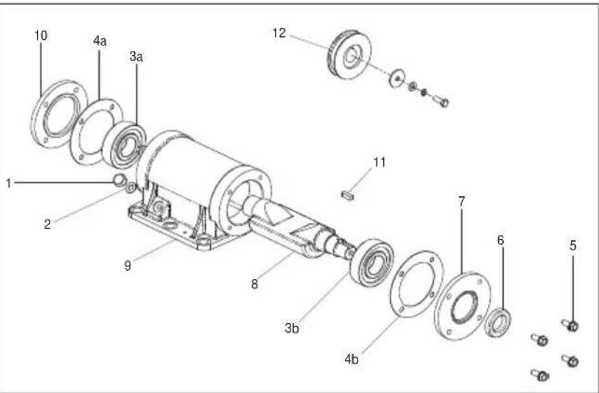
text_image
Exploded view diagram of a mechanical assembly with numbered parts for identification
text_image
Technical diagram of a mechanical assembly with numbered components labeled 1 to 5Belle Group Warranty Department,
Unit 5 Bode Business Park,
Ball Haye Green,
Leek,
Staffordshire
ST13 6BW,
England
Tel: +44 (0)1538 380000 Fax: +44 (0)1538 380038
Email : warranty@belle-group.co.uk
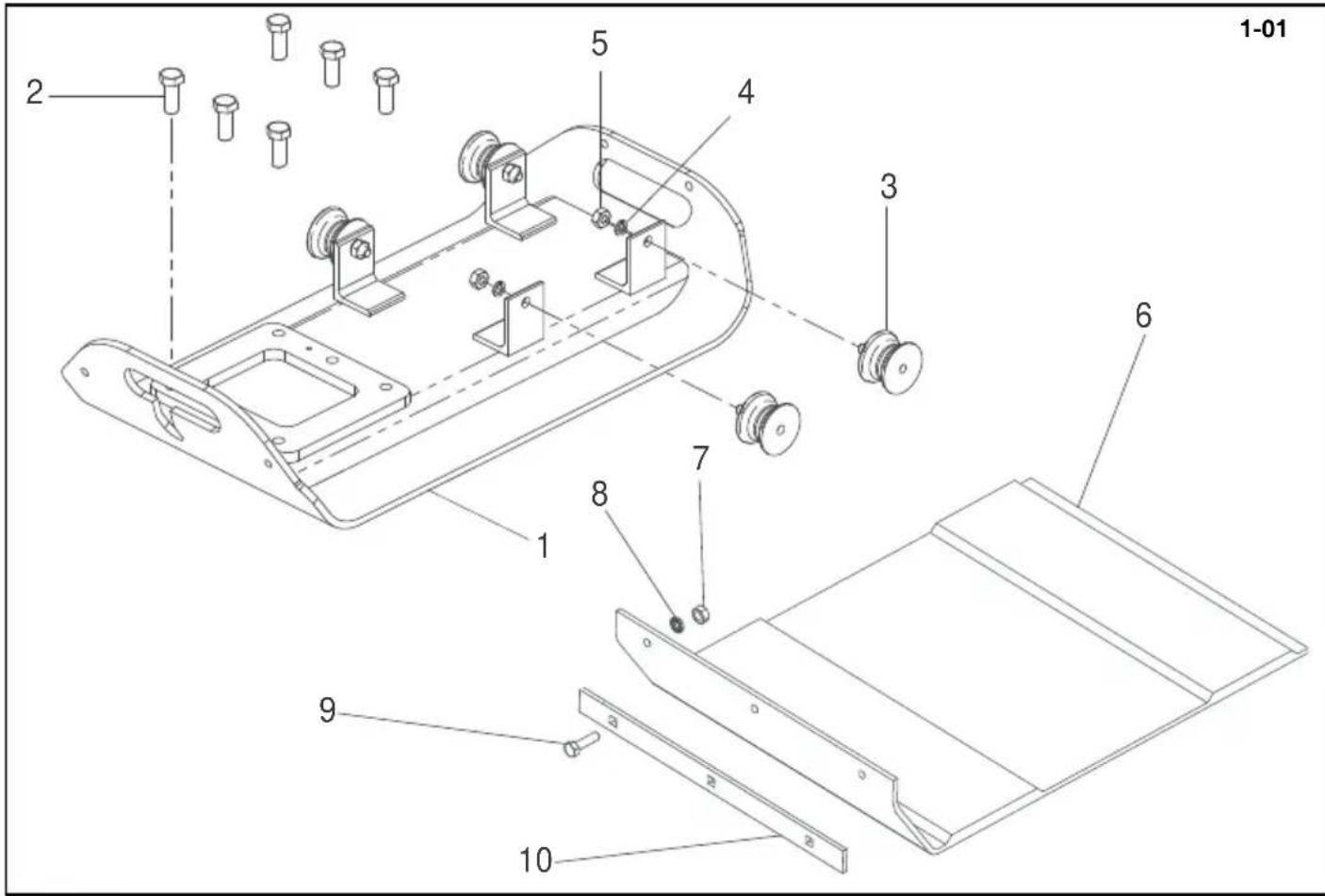
text_image
1-01 2 5 4 3 6 7 8 1 9 10Baseplate Assembly (Honda / Robin), Plaque d'embase (Honda / Robin), Cto. Placa base (Honda / Robin), Conj. da Placa de Base (Honda / Robin)
1-01
| 1 | 151/02600 | Baseplate | Plaque d'embase | Placa de base | Placa de Base | PCX 350 | 1 |
| 1 | 151/02600 | Baseplate | Plaque d'embase | Placa de base | Placa de Base | PCX 350 HAUC | 1 |
| 1 | 151/02600 | Baseplate | Plaque d'embase | Placa de base | Placa de Base | PCX 350A | 1 |
| 1 | 151/02600 | Baseplate | Plaque d'embase | Placa de base | Placa de Base | PCX 350A HAUC | 1 |
| 1 | 151/02700 | Baseplate | Plaque d'embase | Placa de base | Placa de Base | PCX 400 | 1 |
| 1 | 151.0.215 | Baseplate | Plaque d'embase | Placa de base | Placa de Base | PCX 400 HAUC | 1 |
| 1 | 151.0.363 | Baseplate | Plaque d'embase | Placa de base | Placa de Base | PCX 400A | 1 |
| 1 | 151.0.386 | Baseplate | Plaque d'embase | Placa de base | Placa de Base | PCX 400A HAUC | 1 |
| 1 | 151/02800 | Baseplate | Plaque d'embase | Placa de base | Placa de Base | PCX 450 | 1 |
| 1 | 151/02800 | Baseplate | Plaque d'embase | Placa de base | Placa de Base | PCX 450 HAUC | 1 |
| 1 | 151/02800 | Baseplate | Plaque d'embase | Placa de base | Placa de Base | PCX 450A | 1 |
| 1 | 151/02800 | Baseplate | Plaque d'embase | Placa de base | Placa de Base | PCX 450A HAUC | 1 |
| 1 | 151/02900 | Baseplate | Plaque d'embase | Placa de base | Placa de Base | PCX 500 | 1 |
| 1 | 151/02900 | Baseplate | Plaque d'embase | Placa de base | Placa de Base | PCX 500 HAUC | 1 |
| 1 | 151/02900 | Baseplate | Plaque d'embase | Placa de base | Placa de Base | PCX 500A | 1 |
| 1 | 151/02900 | Baseplate | Plaque d'embase | Placa de base | Placa de Base | PCX 500A HAUC | 1 |
| 2 | 07.9.062 | Screw | Vis | Tornillo | Parafuse | M14 x 35 | 6 |
| 3 | 21.0.292 | Anti-Vibration Mount | Tampon antivibratoire | Montura antivibratoria | Bloco Anti-vibração | Honda Robin | 4 |
| 3 | 21.0.298 | Anti-Vibration Mount | Tampon antivibratoire | Montura antivibratoria | Bloco Anti-vibração | Hatz | 4 |
| 4 | 4/1003 | Washer | Rondelle | Arandela | Anilha | M10 | 4 |
| 5 | 8/10003 | Nut | Ecrou | Tuerca | Porca | M10 | 4 |
| 6 | 151.0.271 | Paving Pad | Tampon de Pavage | Tampón de Pavimentación | Bloco de Pavimentação | PCX 350 | 1 |
| 6 | 151.0.272 | Paving Pad | Tampon de Pavage | Tampón de Pavimentación | Bloco de Pavimentação | PCX 350 HAUC | 1 |
| 6 | 151.0.273 | Paving Pad | Tampon de Pavage | Tampón de Pavimentación | Bloco de Pavimentação | PCX 400 | 1 |
| 6 | 151.0.274 | Paving Pad | Tampon de Pavage | Tampón de Pavimentación | Bloco de Pavimentação | PCX 400 HAUC | 1 |
| 6 | 151.0.275 | Paving Pad | Tampon de Pavage | Tampón de Pavimentación | Bloco de Pavimentação | PCX 450 | 1 |
| 6 | 151.0.276 | Paving Pad | Tampon de Pavage | Tampón de Pavimentación | Bloco de Pavimentação | PCX 450 HAUC | 1 |
| 6 | 151.0.277 | Paving Pad | Tampon de Pavage | Tampón de Pavimentación | Bloco de Pavimentação | PCX 500 | 1 |
| 6 | 151.0.278 | Paving Pad | Tampon de Pavage | Tampón de Pavimentación | Bloco de Pavimentação | PCX 500 HAUC | 1 |
| 7 | 8/8008 | Nut | Ecrou | Tuerca | Porca | M8 | 2 |
| 8 | 4/8006 | Washer | Rondelle | Arandela | Anilha | M8 | 2 |
| 9 | 00.0.860 | Bolt | Boulon | Perno | Perno | M8 x 30 | 2 |
| 10 | 151.0.284 | Clamp Strip | Barrette de blocage | Barra de fijación | Tira de Grampeamento | PCX 350 | 1 |
| 10 | 151.0.285 | Clamp Strip | Barrette de blocage | Barra de fijación | Tira de Grampeamento | PCX 400 | 1 |
| 10 | 151.0.286 | Clamp Strip | Barrette de blocage | Barra de fijación | Tira de Grampeamento | PCX 450 | 1 |
| 10 | 151.0.287 | Clamp Strip | Barrette de blocage | Barra de fijación | Tira de Grampeamento | PCX 500 | 1 |

text_image
1-01 2 5 4 3 6 7 8 1 9 10Vloerplaat (Honda / Robin), Rüttelplatten-Zsb. (Honda / Robin), Bundplade (Honda / Robin), Gruppo piastra di base (Honda / Robin)
1-01
| 1 | 151/02600 | Vloerplaat | Rüttelplatten | Bundplade | Piastra di Base | PCX 350 | 1 |
| 1 | 151/02600 | Vloerplaat | Rüttelplatten | Bundplade | Piastra di Base | PCX 350 HAUC | 1 |
| 1 | 151/02600 | Vloerplaat | Rüttelplatten | Bundplade | Piastra di Base | PCX 350A | 1 |
| 1 | 151/02600 | Vloerplaat | Rüttelplatten | Bundplade | Piastra di Base | PCX 350A HAUC | 1 |
| 1 | 151/02700 | Vloerplaat | Rüttelplatten | Bundplade | Piastra di Base | PCX 400 | 1 |
| 1 | 151.0.215 | Vloerplaat | Rüttelplatten | Bundplade | Piastra di Base | PCX 400 HAUC | 1 |
| 1 | 151.0.363 | Vloerplaat | Rüttelplatten | Bundplade | Piastra di Base | PCX 400A | 1 |
| 1 | 151.0.386 | Vloerplaat | Rüttelplatten | Bundplade | Piastra di Base | PCX 400A HAUC | 1 |
| 1 | 151/02800 | Vloerplaat | Rüttelplatten | Bundplade | Piastra di Base | PCX 450 | 1 |
| 1 | 151/02800 | Vloerplaat | Rüttelplatten | Bundplade | Piastra di Base | PCX 450 HAUC | 1 |
| 1 | 151/02800 | Vloerplaat | Rüttelplatten | Bundplade | Piastra di Base | PCX 450A | 1 |
| 1 | 151/02800 | Vloerplaat | Rüttelplatten | Bundplade | Piastra di Base | PCX 450A HAUC | 1 |
| 1 | 151/02900 | Vloerplaat | Rüttelplatten | Bundplade | Piastra di Base | PCX 500 | 1 |
| 1 | 151/02900 | Vloerplaat | Rüttelplatten | Bundplade | Piastra di Base | PCX 500 HAUC | 1 |
| 1 | 151/02900 | Vloerplaat | Rüttelplatten | Bundplade | Piastra di Base | PCX 500A | 1 |
| 1 | 151/02900 | Vloerplaat | Rüttelplatten | Bundplade | Piastra di Base | PCX 500A HAUC | 1 |
| 2 | 07.9.062 | Schroef | Schraube | Skrue | Vite | M14 x 35 | 6 |
| 3 | 21.0.292 | Anti-trilbevestiging | Schwingungsdämpfer | Antivibrationsophaeng | Supporto antivibrazioni | Honda/Robin | 4 |
| 3 | 21.0.298 | Anti-trilbevestiging | Schwingungsdämpfer | Antivibrationsophaeng | Supporto antivibrazioni | Hatz | 4 |
| 4 | 4/1003 | Afdichtring | Scheibe | Spændeskive | Rondella | M10 | 4 |
| 5 | 8/10003 | Moer | Mutter | Motrik | Dado | M10 | 4 |
| 6 | 151.0.271 | Kunststof onderplaat | Blockpflasterrüttler | Belægningsklods | Pavimentazione a Blocchi | PCX 350 | 1 |
| 6 | 151.0.272 | Kunststof onderplaat | Blockpflasterrüttler | Belægningsklods | Pavimentazione a Blocchi | PCX 350 HAUC | 1 |
| 6 | 151.0.273 | Kunststof onderplaat | Blockpflasterrüttler | Belægningsklods | Pavimentazione a Blocchi | PCX 400 | 1 |
| 6 | 151.0.274 | Kunststof onderplaat | Blockpflasterrüttler | Belægningsklods | Pavimentazione a Blocchi | PCX 400 HAUC | 1 |
| 6 | 151.0.275 | Kunststof onderplaat | Blockpflasterrüttler | Belægningsklods | Pavimentazione a Blocchi | PCX 450 | 1 |
| 6 | 151.0.276 | Kunststof onderplaat | Blockpflasterrüttler | Belægningsklods | Pavimentazione a Blocchi | PCX 450 HAUC | 1 |
| 6 | 151.0.277 | Kunststof onderplaat | Blockpflasterrüttler | Belægningsklods | Pavimentazione a Blocchi | PCX 500 | 1 |
| 6 | 151.0.278 | Kunststof onderplaat | Blockpflasterrüttler | Belægningsklods | Pavimentazione a Blocchi | PCX 500 HAUC | 1 |
| 7 | 8/8008 | Moer | Mutter | Motrik | Dado | M8 | 2 |
| 8 | 4/8006 | Afdichtring | Scheibe | Spændeskive | Rondella | M8 | 2 |
| 9 | 00.0.860 | Schroef | Schraube | Skrue | Vite | M8 x 30 | 2 |
| 10 | 151.0.284 | Clamp Strip | Barrette de blocage | Barra de fijación | Tira de Grampeamento | PCX 350 | 1 |
| 10 | 151.0.285 | Clamp Strip | Barrette de blocage | Barra de fijación | Tira de Grampeamento | PCX 400 | 1 |
| 10 | 151.0.286 | Clamp Strip | Barrette de blocage | Barra de fijación | Tira de Grampeamento | PCX 450 | 1 |
| 10 | 151.0.287 | Clamp Strip | Barrette de blocage | Barra de fijación | Tira de Grampeamento | PCX 500 | 1 |
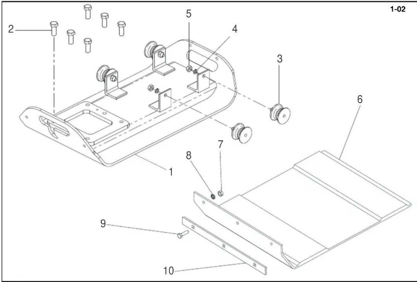
text_image
1-02 2 5 4 3 6 7 8 1 9 10Baseplate Assembly (Hatz), Plaque d'embase (Hatz), Cto. Placa base (Hatz), Conj. da Placa de Base (Hatz)
1-02
| 1 | 151/02700 | Baseplate | Plaque d'embase | Placa de base | Placa de Base | PCX 400 | 1 |
| 1 | 151/02800 | Baseplate | Plaque d'embase | Placa de base | Placa de Base | PCX 450 | 1 |
| 1 | 151/02900 | Baseplate | Plaque d'embase | Placa de base | Placa de Base | PCX 500 | 1 |
| 1 | 151.0.412 | Baseplate | Plaque d'embase | Placa de base | Placa de Base | PCX 400 HAUC | 1 |
| 1 | 151/02800 | Baseplate | Plaque d'embase | Placa de base | Placa de Base | PCX 450 HAUC | 1 |
| 1 | 151/02900 | Baseplate | Plaque d'embase | Placa de base | Placa de Base | PCX 500 HAUC | 1 |
| 1 | 151.0.415 | Baseplate | Plaque d'embase | Placa de base | Placa de Base | PCX 400A | 1 |
| 1 | 151/02800 | Baseplate | Plaque d'embase | Placa de base | Placa de Base | PCX 450A | 1 |
| 1 | 151/02900 | Baseplate | Plaque d'embase | Placa de base | Placa de Base | PCX 500A | 1 |
| 1 | 151.0.418 | Baseplate | Plaque d'embase | Placa de base | Placa de Base | PCX 400 HAUC A | 1 |
| 1 | 151/02800 | Baseplate | Plaque d'embase | Placa de base | Placa de Base | PCX 450 HAUC A | 1 |
| 1 | 151/02900 | Baseplate | Plaque d'embase | Placa de base | Placa de Base | PCX 500 HAUC A | 1 |
| 2 | 07.9.062 | Screw | Vis | Tornillo | Parafuse | M14 x 35 | 6 |
| 3 | 21.0.292 | Anti-Vibration Mount | Tampon antivibratoire | Montura antivibratoria | Bloco Anti-vibração | Honda Robin | 4 |
| 3 | 21.0.298 | Anti-Vibration Mount | Tampon antivibratoire | Montura antivibratoria | Bloco Anti-vibração | Hatz | 4 |
| 4 | 4/1003 | Washer | Rondelle | Arandela | Anilha | M10 | 4 |
| 5 | 8/10003 | Nut | Ecrou | Tuerca | Porca | M10 | 4 |
| 6 | 151.0.271 | Paving Pad | Tampon de Pavage | Tampón de Pavimentación | Bloco de Pavimentação | PCX 350 | 1 |
| 6 | 151.0.272 | Paving Pad | Tampon de Pavage | Tampón de Pavimentación | Bloco de Pavimentação | PCX 350 HAUC | 1 |
| 6 | 151.0.273 | Paving Pad | Tampon de Pavage | Tampón de Pavimentación | Bloco de Pavimentação | PCX 400 | 1 |
| 6 | 151.0.274 | Paving Pad | Tampon de Pavage | Tampón de Pavimentación | Bloco de Pavimentação | PCX 400 HAUC | 1 |
| 6 | 151.0.275 | Paving Pad | Tampon de Pavage | Tampón de Pavimentación | Bloco de Pavimentação | PCX 450 | 1 |
| 6 | 151.0.276 | Paving Pad | Tampon de Pavage | Tampón de Pavimentación | Bloco de Pavimentação | PCX 450 HAUC | 1 |
| 6 | 151.0.277 | Paving Pad | Tampon de Pavage | Tampón de Pavimentación | Bloco de Pavimentação | PCX 500 | 1 |
| 6 | 151.0.278 | Paving Pad | Tampon de Pavage | Tampón de Pavimentación | Bloco de Pavimentação | PCX 500 HAUC | 1 |
| 7 | 8/8008 | Nut | Ecrou | Tuerca | Porca | M8 | 2 |
| 8 | 4/8006 | Washer | Rondelle | Arandela | Anilha | M8 | 2 |
| 9 | 00.0.860 | Bolt | Boulon | Perno | Perno | M8 x 30 | 2 |
| 10 | 151.0.284 | Clamp Strip | Barrette de blocage | Barra de fijación | Tira de Grampeamento | PCX 350 | 1 |
| 10 | 151.0.285 | Clamp Strip | Barrette de blocage | Barra de fijación | Tira de Grampeamento | PCX 400 | 1 |
| 10 | 151.0.286 | Clamp Strip | Barrette de blocage | Barra de fijación | Tira de Grampeamento | PCX 450 | 1 |
| 10 | 151.0.287 | Clamp Strip | Barrette de blocage | Barra de fijación | Tira de Grampeamento | PCX 500 | 1 |
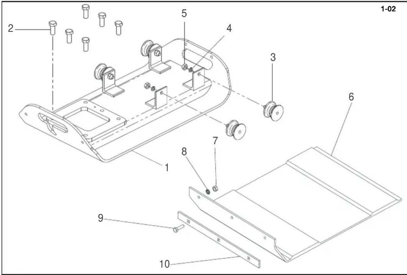
text_image
1-02 2 5 4 3 6 7 8 1 9 3 2 10Vloerplaat (Hatz), Rüttelplatten-Zsb. (Hatz), Bundplade (Hatz), Gruppo piastra di base (Hatz)
1-02
| 1 | 151/02700 | Vloerplaat | Rüttelplatten | Bundplade | Piastra di Base | PCX 400 | 1 |
| 1 | 151/02800 | Vloerplaat | Rüttelplatten | Bundplade | Piastra di Base | PCX 450 | 1 |
| 1 | 151/02900 | Vloerplaat | Rüttelplatten | Bundplade | Piastra di Base | PCX 500 | 1 |
| 1 | 151.0.412 | Vloerplaat | Rüttelplatten | Bundplade | Piastra di Base | PCX 400 HAUC | 1 |
| 1 | 151/02800 | Vloerplaat | Rüttelplatten | Bundplade | Piastra di Base | PCX 450 HAUC | 1 |
| 1 | 151/02900 | Vloerplaat | Rüttelplatten | Bundplade | Piastra di Base | PCX 500 HAUC | 1 |
| 1 | 151.0.415 | Vloerplaat | Rüttelplatten | Bundplade | Piastra di Base | PCX 400A | 1 |
| 1 | 151/02800 | Vloerplaat | Rüttelplatten | Bundplade | Piastra di Base | PCX 450A | 1 |
| 1 | 151/02900 | Vloerplaat | Rüttelplatten | Bundplade | Piastra di Base | PCX 500A | 1 |
| 1 | 151.0.418 | Vloerplaat | Rüttelplatten | Bundplade | Piastra di Base | PCX 400 HAUC A | 1 |
| 1 | 151/02800 | Vloerplaat | Rüttelplatten | Bundplade | Piastra di Base | PCX 450 HAUC A | 1 |
| 1 | 151/02900 | Vloerplaat | Rüttelplatten | Bundplade | Piastra di Base | PCX 500 HAUC A | 1 |
| 2 | 07.9.062 | Schroef | Schraube | Skrue | Vite | M14 x 35 | 6 |
| 3 | 21.0.292 | Anti-trilbevestiging | Schwingungsdämpfer | Antivibrationsophaeng | Supporto antivibrazioni | Honda/Robin | 4 |
| 3 | 21.0.298 | Anti-trilbevestiging | Schwingungsdämpfer | Antivibrationsophaeng | Supporto antivibrazioni | Hatz | 4 |
| 4 | 4/1003 | Afdichtring | Scheibe | Spændeskive | Rondella | M10 | 4 |
| 5 | 8/10003 | Moer | Mutter | Motrik | Dado | M10 | 4 |
| 6 | 151.0.271 | Kunststof onderplaat | Blockpflasterrüttler | Belægningsklods | Pavimentazione a Blocchi | PCX 350 | 1 |
| 6 | 151.0.272 | Kunststof onderplaat | Blockpflasterrüttler | Belægningsklods | Pavimentazione a Blocchi | PCX 350 HAUC | 1 |
| 6 | 151.0.273 | Kunststof onderplaat | Blockpflasterrüttler | Belægningsklods | Pavimentazione a Blocchi | PCX 400 | 1 |
| 6 | 151.0.274 | Kunststof onderplaat | Blockpflasterrüttler | Belægningsklods | Pavimentazione a Blocchi | PCX 400 HAUC | 1 |
| 6 | 151.0.275 | Kunststof onderplaat | Blockpflasterrüttler | Belægningsklods | Pavimentazione a Blocchi | PCX 450 | 1 |
| 6 | 151.0.276 | Kunststof onderplaat | Blockpflasterrüttler | Belægningsklods | Pavimentazione a Blocchi | PCX 450 HAUC | 1 |
| 6 | 151.0.277 | Kunststof onderplaat | Blockpflasterrüttler | Belægningsklods | Pavimentazione a Blocchi | PCX 500 | 1 |
| 6 | 151.0.278 | Kunststof onderplaat | Blockpflasterrüttler | Belægningsklods | Pavimentazione a Blocchi | PCX 500 HAUC | 1 |
| 7 | 8/8008 | Moer | Mutter | Motrik | Dado | M8 | 2 |
| 8 | 4/8006 | Afdichtring | Scheibe | Spændeskive | Rondella | M8 | 2 |
| 9 | 00.0.860 | Schroef | Schraube | Skrue | Vite | M8 x 30 | 2 |
| 10 | 151.0.284 | Clamp Strip | Barrette de blocage | Barra de fijación | Tira de Grampeamento | PCX 350 | 1 |
| 10 | 151.0.285 | Clamp Strip | Barrette de blocage | Barra de fijación | Tira de Grampeamento | PCX 400 | 1 |
| 10 | 151.0.286 | Clamp Strip | Barrette de blocage | Barra de fijación | Tira de Grampeamento | PCX 450 | 1 |
| 10 | 151.0.287 | Clamp Strip | Barrette de blocage | Barra de fijación | Tira de Grampeamento | PCX 500 | 1 |
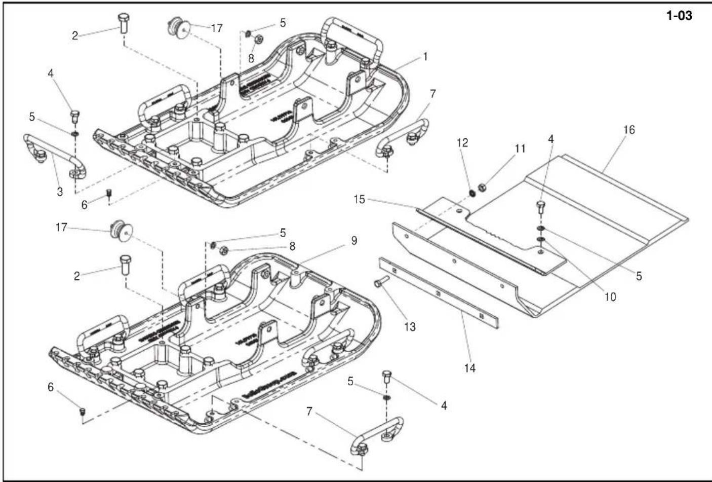
text_image
1-03 17 5 8 2 4 5 3 6 17 5 8 9 2 6 7 12 11 4 16 15 13 14 5 10 4 5 7text_image
Technical diagram of a mechanical assembly with numbered components for identification4-01
Handle Assembly, Ensemble poignée, Conjunto de manillar, Conjunto do Punho
4-01
text_image
Technical diagram of a mechanical assembly with numbered components for identification4-01
Hendel, Griff-Zsb., Hovedstel Og Dæksel, Gruppo impugnatura
4-01
| 1 | 151/00100SF....Hendel - Orange......Griff - Orange......Händtag - Orange......Impugnatura - Arancione......1 |
| 1 | 151/00100BF....Hendel - Blå......Griff - Blau......Händtag - Blauw......Impugnatura - Blu......1 |
| 1 | 151/00100GF....Hendel - Groen......Griff - Grün......Händtag - Gron......Impugnatura - Verde......A - Plant......1 |
| 1 | 151/00100RF....Hendel - Rood......Griff - Rot......Händtag - Rød......Impugnatura - Rosso......1 |
| 1 | 151/00100YF....Hendel - Geel......Griff - Gelb......Händtag - Gul......Impugnatura - Giallo......1 |
| 1 | 151/00100WF....Handle - Wit......Guidon - Weiß......Manillar - Hvid......Punho - Bianco......1 |
| 2 | 151.0.019......Schroef......Schraube......Skrue......Vite......2 |
| 3 | 151/99906......Beugel......Halterung......Beslag......Staffa......→013118......1 |
| 3 | 151/99921......Beugel......Halterung......Beslag......Staffa......→013119......1 |
| 4 | 4/8006......Afdichtring......Scheibe......Spændeskive......Cuscinetto......M8......4 |
| 5 | 8/8008......Moer......Mutter......Motrik......Dado......M8......4 |
| 6 | 151/99901......Steuun......Sprosse......Puntal......Montante......1 |
| 7 | 151/99905......Beugel......Halterung......Beslag......Staffa......→013118......1 |
| 7 | 151/99920......Beugel......Halterung......Beslag......Staffa......→013119......1 |
| 8 | 21/0157......Anti-trilbevestiging......Schwingungsdämpfer......Antivibrationsophæng......Supporto antivibrazioni......4 |
5-01
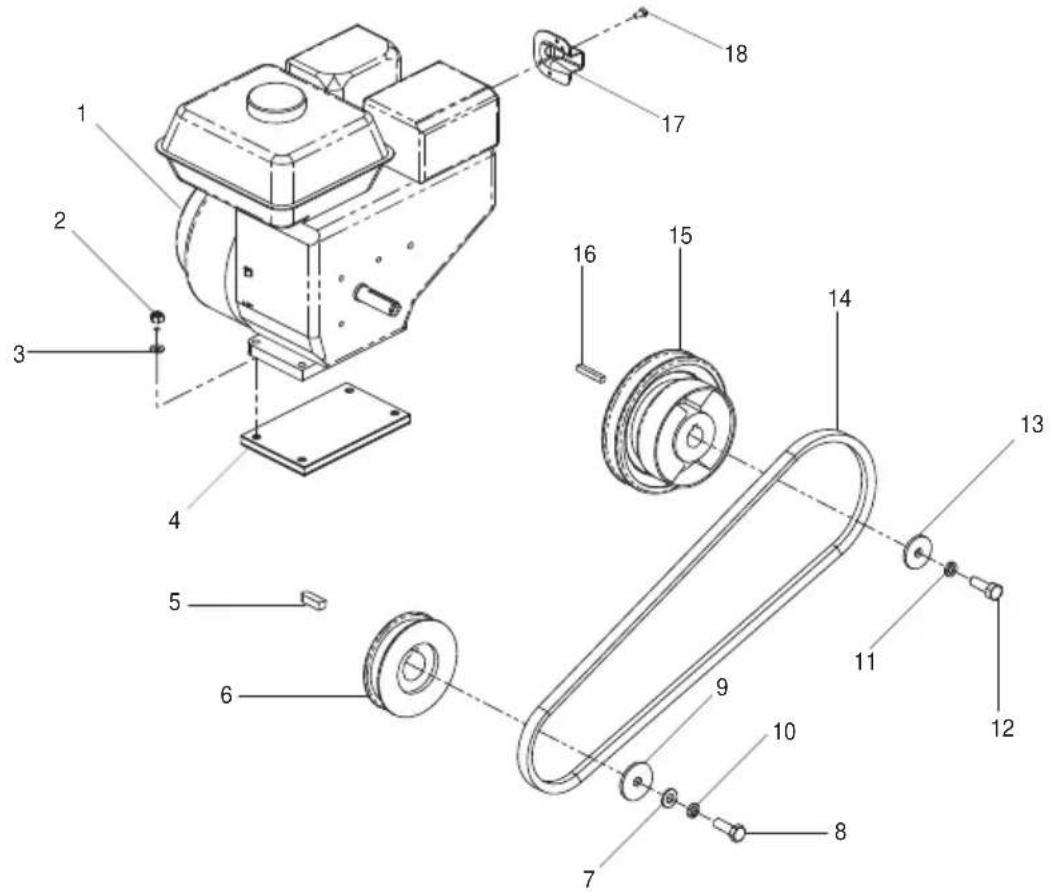
text_image
Exploded view diagram of a mechanical device with numbered parts for identificationtext_image
Exploded view diagram of a mechanical device with numbered parts for identificationMotor en Aandrijfset (Honda / Robin), Motor und antriebsbausatz (Honda / Robin), Motor og Gearkit (Honda / Robin), Motore e Kit trasmissione (Honda / Robin)
5-01
| 1 | 29.1.149 | Motor | Motor | Motor | Motore | Honda GX 120 | 1 |
| 1 | 29.1.129 | Motor | Motor | Motor | Motore | Honda GX 160 | 1 |
| 1 | 20/0038 | Motor | Motor | Motor | Motore | Honda GX 120 EPA | 1 |
| 1 | 20/0039 | Motor | Motor | Motor | Motore | Honda GX 160 EPA | 1 |
| 1 | 20/0056 | Motor | Motor | Motor | Motore | Robin EX 13 | 1 |
| 1 | 20/0057 | Motor | Motor | Motor | Motore | Robin EX 17 | 1 |
| 2 | 8/8008 | Moer | Mutter | Motrik | Dado | M8 | 4 |
| 3 | 4/8006 | Afdichtring | Scheibe | Spændeskive | Cuscinetto | M8 | 4 |
| 4 | 151.0.236 | Onderplaat - Antitrillstuk | Dämpfungsbeilage | Klods - Antivibration | Tampone - Antivibrazione | 1 | |
| 5 | 06.3.014 | Spie | Keil | Kile | Chiave | 1 | |
| 6 | 151.0.221 | Poelie | Riemenscheibe | Remskive | Puleggia | 1 | |
| 7 | 4/8006 | Afdichtring | Scheibe | Spændeskive | Cuscinetto | M8 | 1 |
| 8 | 7/8012 | Schroef | Schraube | Skrue | Vite | M8 x 25 | 1 |
| 9 | 77.0.142 | Afdichtring | Scheibe | Spændeskive | Cuscinetto | 1 | |
| 10 | 4/8003 | Afdichtring | Scheibe | Spændeskive | Cuscinetto | 1 | |
| 11 | 4/8003 | Afdichtring | Scheibe | Spændeskive | Cuscinetto | 1 | |
| 12 | 02.3.020 | Schroef | Schraube | Skrue | Vite | 5/16" × 1" | 1 |
| 13 | 05.3.062 | Afdichtring | Scheibe | Spændeskive | Cuscinetto | 1 | |
| 14 | 11.4.019 | Riem | Riemen | Remmen | Cinghia | 1 | |
| 15 | 10.7.255 | Kuppling | Koppeling | Kobling | Frizione | 3/4" | 1 |
| 16 | 06.8.001 | Spie | Keil | Kile | Chiave | 1 | |
| 17 | 21.0.149 | Beschermingsplaat | Schutzplatte | Skæmplade | Piastra di protezione | 1 | |
| 18 | 21.0.140 | Schroef | Schraube | Skrue | Vite | 5/16" | 2 |
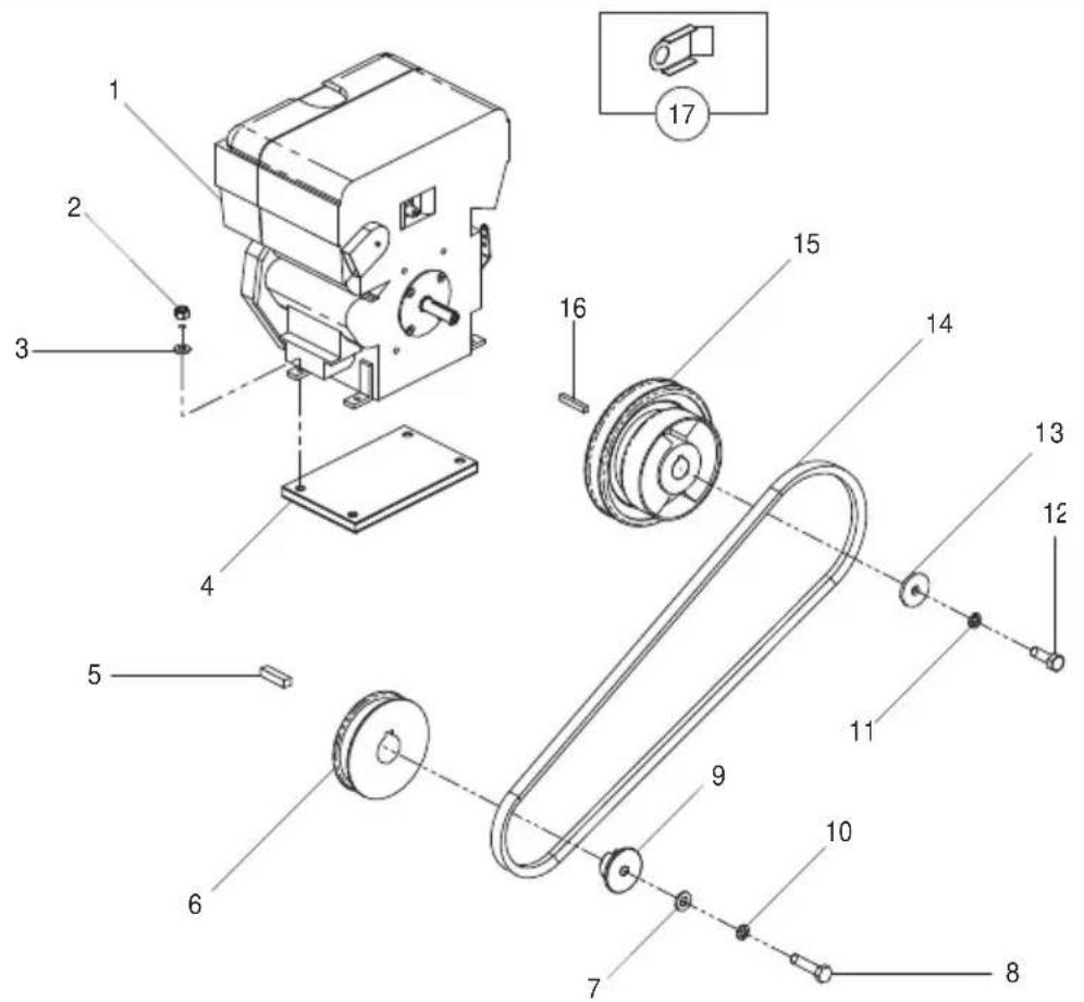
text_image
Technical diagram of an industrial machine with numbered components and exploded view5-02
text_image
Technical diagram of an industrial machine with numbered components and exploded view5-02
Motor en Aandrijfset (Hatz), Motor und antriebsbausatz (Hatz), Motor og Gearkit (Hatz), Motore e Kit trasmissione (Hatz)
5-02
| 1 | 29.0.455 | Motor | Motor | Motor | Motore | Hatz 1B20 | 1 |
| 2 | 8/8008 | Moer | Mutter | Møtrik | Dado | M8 | 4 |
| 3 | 4/8006 | Afdichtring | Scheibe | Spændeskive | Cuscinetto | M8 | 4 |
| 4 | 151.0.309 | Onderplaat - Antitrilstuk | Dämpfungsbeilage | Klods - Antivibration | Tampone - Antivibrazione | Hatz 1B20 | 1 |
| 5 | 06.3.003 | Spie | Keil | Kile | Chiave | 8 x 7 x 30mm | 1 |
| 6 | 151.0.393 | Poelie | Riemenscheibe | Remskive | Puleggia | 1 | |
| 7 | 4/8006 | Afdichtring | Scheibe | Spændeskive | Cuscinetto | M8 | 1 |
| 8 | 7/8007 | Schroef | Schraube | Skrue | Vite | M8 x 35 | 1 |
| 9 | 151.0.394 | Afstandsstuk | Distanzstück | Afstandsstykke | Distanziale | 1 | |
| 10 | 4/8003 | Afdichtring | Scheibe | Spændeskive | Cuscinetto | 1 | |
| 11 | 4/8003 | Afdichtring | Scheibe | Spændeskive | Cuscinetto | 1 | |
| 12 | 02.3.020 | Schroef | Schraube | Skrue | Vite | 5/16" x 1" | 1 |
| 13 | 05.3.062 | Afdichtring | Scheibe | Spændeskive | Cuscinetto | 1 | |
| 14 | 11.4.020 | Riem | Riemen | Remmen | Cinghia | 1 | |
| 15 | 10.7.255 | Kuppling | Koppeling | Kobling | Frizione | 3/4" | 1 |
| 16 | 06.8.001 | Spie | Keil | Kile | Chiave | 3/16" x 1.25" | 1 |
| 17 | 151.0.345 | Beschermingsplaat | Schutzplatte | Skæmplade | Piastra di protezione | 1 |
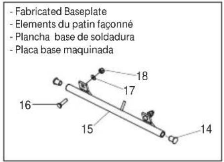
text_image
- Fabricated Baseplate - Elements du patin façonné - Plancha base de soldadura - Placa base maquinada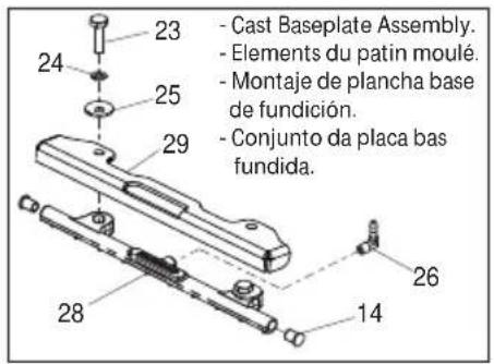
text_image
Technical diagram of a device with numbered parts, likely an industrial or mechanical assembly, showing exploded and assembled views.Voorop Gemonteerd Waterreservoir, Frontmontieter Wasserbehälter, Frontmonteret vandfl aske, Serbatoio di espansione a montaggio in posizione anteriore
6-01
| 1 | 942/99901S...Tank - Oranje....Tank - Orange....Tank - Orange....Serbatoio - Arancione....1 |
| 1 | 942/99901R...Tank - Ruud....Tank - Rot....Tank - Rod....Serbatoio - Rosso....1 |
| 1 | 942/99901Y...Tank - Geel....Tank - Gelb....Tank - Gul....Serbatoio - Giallo....1 |
| 1 | 942/99901B...Tank - Blauw....Tank - Blau....Tank - Blå....Serbatoio - Blu....1 |
| 1 | 942/99901G...Tank - Groen....Tank - Grün....Tank - Grøn....Serbatoio - Verde....1 |
| 1 | 942/99901W...Tank - Wit....Tank - Weiß....Tank - Hvid....Serbatoio - Blanco....1 |
| 2 | 942/99903...Kemplaat...Drukklemmplatte...Plade, Presset, Klampe...Morsetto Di Compressione Piastra....1 |
| 3 | 7/10010....Schroef....Schraube....Skrue....Vite....M10 x 30....2 |
| 4 | 4/1005....Afdichtring....Scheibe....Spændeskive....Cuscinetto....M10....4 |
| 5 | 8/10006....Moer....Mutter....Møtrik....Dado....M10....2 |
| 6 | 5/0007....Afdichtring....Dichtung....Tætning....Tenuta....1 |
| 7 | 6/0146....Adaptor....Adaptor....Adattatore....1/4F x 3/8M....1 |
| 8 | 6/0193....Elleboogstuk....Krümmer....Vinkelstykke....Gomito....1 |
| 9 | 6/0199....Kogelklep....Kugelventil....Kugleventil....Valvola A Sfera....1 |
| 10 | 6/0201....Adaptor....Adaptor....Adattatore....1/4"F x 1/4"....1 |
| 11 | 15.0.063....Slangklem....Schlauchschelle....Slangeklemme....Fermaglio Per Flessible....1 |
| 12 | 942/99905....Slang....Schlauchstück....Slange....Flessible....1/4"....1 |
| 13 | 15.0.063....Slangklem....Schlauchschelle....Slangeklemme....Fermaglio Per Flessible....1 |
| 14 | 3/4040....Inzetstuk....Einsatz....Indsats....Inserto....2 |
| 15 | 151.0.379....Watersproeier Gelast....Sprühwasser Schweißvorrichtung....Sprinkler, Svejset Enhed....Diffusore Acqua....PCX 350....1 |
| 15 | 151.0.380....Watersproeier Gelast....Sprühwasser Schweißvorrichtung....Sprinkler, Svejset Enhed....Diffusore Acqua....PCX 400....1 |
| 15 | 151.0.381....Watersproeier Gelast....Sprühwasser Schweißvorrichtung....Sprinkler, Svejset Enhed....Diffusore Acqua....PCX 450....1 |
| 15 | 151.0.382....Watersproeier Gelast....Sprühwasser Schweißvorrichtung....Sprinkler, Svejset Enhed....Diffusore Acqua....PCX 500....1 |
| 16 | 00.0.860....Schroef....Schraube....Skrue....Vite....M8 x 30....1 |
| 17 | 4/8006....Afdichtring....Scheibe....Spændeskive....Cuscinetto....M8....1 |
| 18 | 8/8008....Moer....Mutter....Møtrik....Dado....M8....1 |
| 19 | 8/10006....Moer....Mutter....Møtrik....Dado....M10....1 |
| 20 | 4/1005....Afdichtring....Scheibe....Spændeskive....Cuscinetto....M10....2 |
| 21 | 942-99902...Kemplaat...Drukklemmplatte...Plade, Presset, Klampe...Morsetto Di Compressione Piastra....1 |
| 22 | 800/99960...Label....Abziehbild....Skilt....Decalcomania....PCX 350....1 |
| 22 | 800/99961...Label....Abziehbild....Skilt....Decalcomania....PCX 400....1 |
| 22 | 800/99962...Label....Abziehbild....Skilt....Decalcomania....PCX 450....1 |
| 22 | 800/99963...Label....Abziehbild....Skilt....Decalcomania....PCX 500....1 |
| 23 | 7/10003....Schroef....Schraube....Skrue....Vite....M10 x 35....2 |
| 24 | 4/1003....Afdichtring....Scheibe....Spændeskive....Cuscinetto....M10....2 |
| 25 | 151/99941...Plaat....Platte....Blade....Piastra....→046927....2 |
| 26 | 6/0215....Elleboogstuk....Krümmer....Vinkelstykke....Gomito....1/8"....1 |
| 28 | 151/99938....Watersproeier Gelast....Sprühwasser Schweißvorrichtung....Sprinkler, Svejset Enhed....Diffusore Acqua....PCX 350....1 |
| 28 | 151/99939....Watersproeier Gelast....Sprühwasser Schweißvorrichtung....Sprinkler, Svejset Enhed....Diffusore Acqua....PCX 400....1 |
| 28 | 151/99940....Watersproeier Gelast....Sprühwasser Schweißvorrichtung....Sprinkler, Svejset Enhed....Diffusore Acqua....PCX 450/500....1 |
| 29 | 151/99960....Guard....Capot....Protector....Guarda....→046928 (PCX 350)....1 |
| 29 | 151/99959....Guard....Capot....Protector....Guarda....→046928 (PCX 400)....1 |
| 29 | 151/99958....Guard....Capot....Protector....Guarda....→046928 (PCX 450 & 500)....1 |
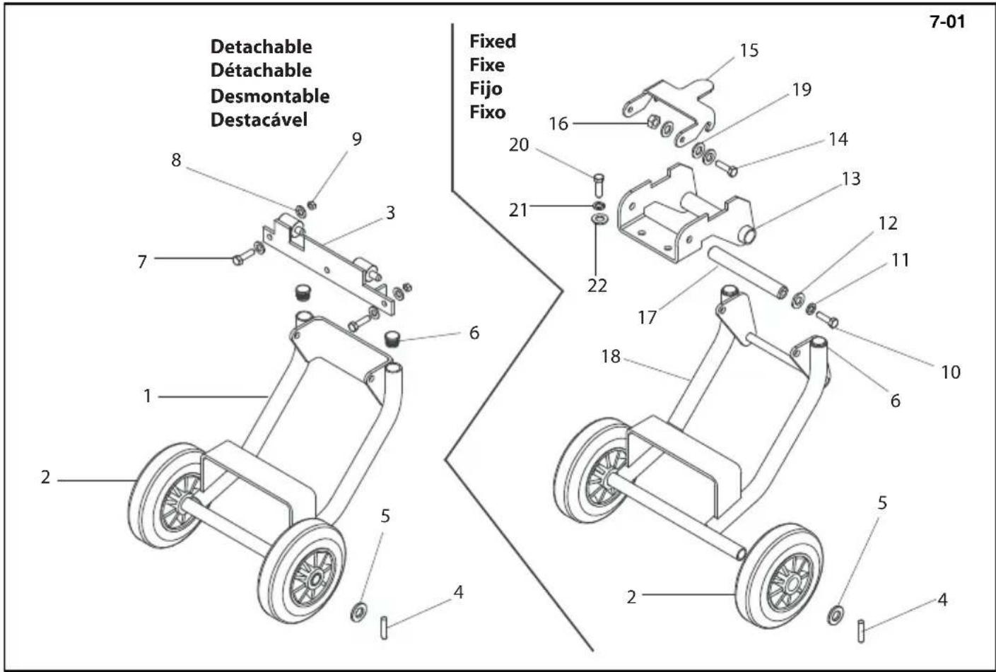
text_image
Detachable Détachable Desmontable Destacável Fixed Fixe Fijo Fixo 7-01 8 9 3 7 6 20 15 19 14 21 13 22 12 11 17 18 10 6 5 4 2 5 2 4Transporter Attachments (Fabricated Baseplate), Fixation de transporteur (Elements du patin façonné), 7-01 Conexión para transportador (Plancha base de soldadura), Conexión para transportador (Placa base maquinada)
| 1 | 151.0.246 | Transporter Weldment | AssemblageSoude DeTransporteur | Cjto. Transportador Soldado | Soldadura Do Transportador | 1 |
| 2 | 19.0.603 | Wheel | Roue | Rueda | Roda | 2 |
| 3 | 151.0.241 | Bracket | Patte de Montage | Escuadra | Suporte | 1 |
| 4 | 06.1.009 | Pin | Goupille | Pasador | Pino | 6 x 30mm |
| 5 | 05.0.030 | Washer | Rondelle | Arandela | Anilha | M10 |
| 6 | 21.0.259 | Insert | Insert | Pieza Intercalada | Inserção | 2 |
| 7 | 7/8009 | Screw | Vis | Tornillo | Parafuso | M8 x 30 |
| 8 | 4/8006 | Washer | Rondelle | Arandela | Anilha | M8 |
| 9 | 8/8001 | Nut | Ecrou | Tuerca | Porca | M8 |
| 10 | 7/10004 | Screw | Vis | Tornillo | Parafuso | M10 x 20 |
| 11 | 4/1003 | Washer | Rondelle | Arandela | Anilha | M10 |
| 12 | 4/1005 | Washer | Rondelle | Arandela | Anilha | M10 |
| 13 | 151.0.333 | Bracket | Patte de Montage | Escuadra | Suporte | 1 |
| 14 | 7/10010 | Screw | Vis | Tornillo | Parafuso | M10 x 30 |
| 15 | 151.0.336 | Retaining Hook | Crochet de Retenue | Gancho Reten | Gancho de Retenção | 1 |
| 16 | 8/10006 | Nut | Ecrou | Tuerca | Porca | M10 |
| 17 | 151.0.339 | Shaft | Axe | Eje | Veio | 1 |
| 18 | 151.0.340 | Transporter | Transporteur Fixe | Transportador Tipo Fijo | Transportador Tipo Fixo | M8 |
| 19 | 4/1005 | Washer | Rondelle | Arandela | Anilha | M10 |
| 20 | 7/10004 | Screw | Vis | Tornillo | Parafuso | M10 x 20 |
| 21 | 4/1003 | Washer | Rondelle | Arandela | Anilha | M10 |
| 22 | 4/1005 | Washer | Rondelle | Arandela | Anilha | M10 |
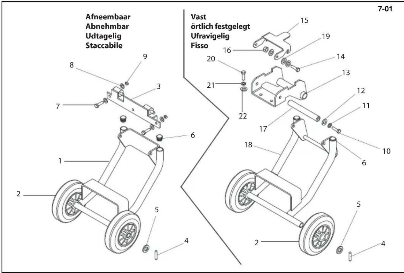
text_image
Afneembaar Abnehmbar Udtagelig Staccabile Vast örtlich festgelegt Ufravigelig Fisso 7-01 8 9 3 7 6 20 15 19 14 21 13 22 12 11 17 18 10 6 5 4 2 5 4Transporthulpstuk (Vervaardigde grondplaat), Transportvorrichtungs-Halterungen (Stahlplatte), 7-01 Transportørudstyr (Metalfundament), Trasportatore (Piastra di base fabricata)
| 1 | 151.0.246 | Transportframe | Transportvorrichtung, Schweißansatz | Transportørsvejsning | Saldatura Del Trasportatore | 1 |
| 2 | 19.0.603 | Wiel | Rad | Hjul | Ruota | 2 |
| 3 | 151.0.241 | Steun | Halterung | Beslag | Staffe | 1 |
| 4 | 06.1.009 | Pen | Zapfen | Stift | Perno | 6 x 30mm |
| 5 | 05.0.030 | Afdichtring | Scheibe | Spændeskive | Cuscinetto | M10 |
| 6 | 21.0.259 | Inzetstuk | Einsatz | Indsats | Inserto | 2 |
| 7 | 7/8009 | Schroef | Schraube | Skrue | Vite | M8 x 30 |
| 8 | 4/8006 | Afdichtring | Scheibe | Spændeskive | Cuscinetto | M8 |
| 9 | 8/8001 | Moer | Mutter | Motrik | Dado | M8 |
| 10 | 7/10004 | Schroef | Schraube | Skrue | Vite | M10 x 20 |
| 11 | 4/1003 | Afdichtring | Scheibe | Spændeskive | Cuscinetto | M10 |
| 12 | 4/1005 | Afdichtring | Scheibe | Spændeskive | Cuscinetto | M10 |
| 13 | 151.0.333 | Steun | Halterung | Beslag | Staffe | 1 |
| 14 | 7/10010 | Schroef | Schraube | Skrue | Vite | M10 x 30 |
| 15 | 151.0.336 | Borghaak | Sicherungshaken | Sikringskrampe | Gancio Di Fissagio | 1 |
| 16 | 8/10006 | Moer | Mutter | Motrik | Dado | M10 |
| 17 | 151.0.339 | As | Welle | Aksel | Albero | 1 |
| 18 | 151.0.340 | Transportframe - Vast | Transportvorrichtung, Fest Eingebaute Type | Transportor – Fast Type | Transportatore - Tipo Fisso | 1 |
| 19 | 4/1005 | Afdichtring | Scheibe | Spændeskive | Cuscinetto | M10 |
| 20 | 7/10004 | Schroef | Schraube | Skrue | Vite | M10 x 20 |
| 21 | 4/1003 | Afdichtring | Scheibe | Spændeskive | Cuscinetto | M10 |
| 22 | 4/1005 | Afdichtring | Scheibe | Spændeskive | Cuscinetto | M10 |
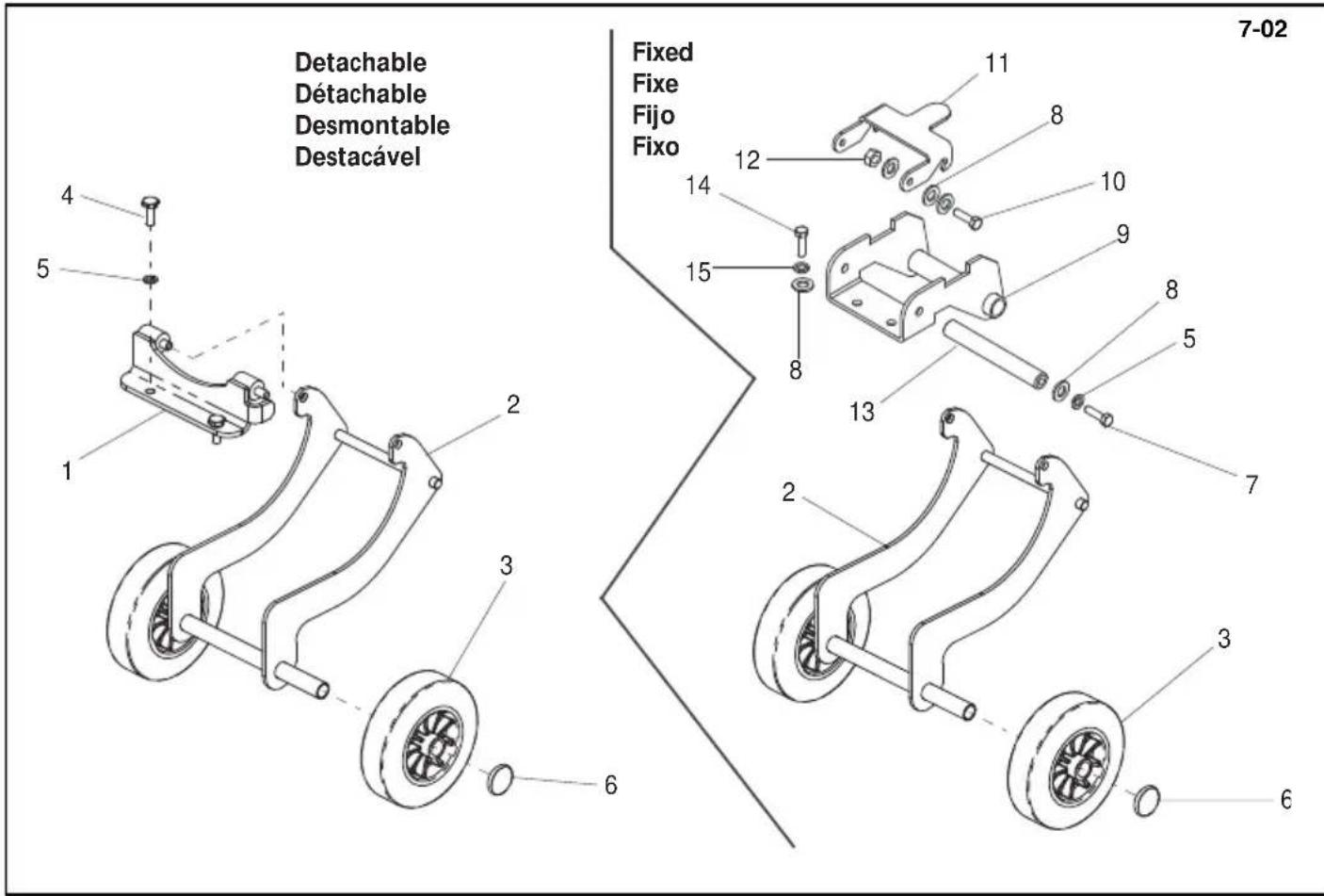
text_image
Detachable Detachable Desmontable Destacável Fixed Fixe Fijo Fixo 7-02 1 2 3 4 5 6 7 8 9 10 11 12 13 14 15 2 3 4 5 6text_image
8-01 6 4 5 APPROVED FOR HAUC 3 2 1 Belle PCX350 107 dBDecals, Autocollant, Rótulo, Decalque
8-01
text_image
8-01 6 4 5 APPROVED FOR HAUC 3 2 1 Belle PCX350 107 dBLabel, Abziehbild, Skilt, Decalcomania
8-01
1 800/99960 .... Label .... Abziehbild .... Skilt .... Decalcomania .... PCX 350 .... 1
1 800/99961 .... Label .... Abziehbild .... Skilt .... Decalcomania .... PCX 400 .... 1
1 800/99962 .... Label .... Abziehbild .... Skilt .... Decalcomania .... PCX 450.... 1
1 800/99963 .... Label .... Abziehbild .... Skilt .... Decalcomania .... PCX 500 .... 1
2 800/99942 .... Label - Guluid.... Abziehbild - Geräuschpegelschild.... Skilt - Skilt Stoj.... Decalcomania - Sulla rumorosità .... Honda GX120 & Robin EX13....1
2 800/99942 .... Label - Guluid.... Abziehbild - Geräuschpegelschild.... Skilt - Skilt Stoj..... Decalcomania - Sulla rumorosità ..... Honda GX160, Robin EX17 & Hatz ..... 1
3 19.0.373 .... Label .... Abziehbild .... Skilt .... Decalcomania .... 1
4 800/99965 .... Label .... Abziehbild .... Skilt .... Decalcomania .... 8 Hrs + .... 1
5 800/99954 .... Label .... Abziehbild .... Skilt .... Decalcomania .... HAUC .... 1
6 800/99743 .... Label - Motor .... Abziehbild - Motor .... Skilt - Motor .... Decalcomania - Motor e .... 1
No.1 for Light Construction Equipment
Belle Group Head Office
Sheen, Nr. Buxton
Derbyshire.
SK17 OEU
GB.
Tel: +44 (0)1298 84606
Fax: +44 (0)1298 84722
email: sales@belle-group.co.uk
Belle France SARL
1 rue de l'Equerre
Zl de Béthunes
BP 20541
95005 Cergy Pontoise Cedex
FRANCE
Tel: +33 (0) 1 34 21 45 83
Tel: +33 (0) 1 34 21 45 84
Fax: +33 (0) 1 30 37 31 28
Belle Equipos SL
Calle Doctor Calero Cial 19,
Local 22, 28220 Majadahonda
Madrid, Spain
Tel: +34 (0) 91 636 2043
Fax: +34 (0) 91 634 1535
Husumer Straße 45 a,
D-33729,
Bielefield
Deutschland
Tel : +49(0) 5217 707505
Fax : +49 (0) 5217 707506
Sales: 0800 1808069
Spares: 0800 1816673
Belle Poland sp. z.o.o.
96-200 Rawa Mazowiecka
Belle Group Portugal
Belle Group Netherlands
Tel: 0800 249861
Belle Group Belguim
Tel: 0800 80295
Belle Group Austria
Tel: 0800 291544
Belle Group Russia
64 Nevsky pr.
St, Petersburg
Russia
Tel : +7(812)314-81-34
Moscow : +7(495)589-64-32
Belle Group South East Asia
21, Jalan Ara AD 7/3B,
Pandar Sri Damansara
S2200 Kuala Lumpur, Malaysia
Tel: +60 (0) 3 62721678
+60 (0) 3 6272 9308
Fax: +60 (0) 3 6272 9528
Belle Group (GB), Shanghai Office
Room 213, Zhonghuang Building,
1007 Zhongshan Nan Er Road,
Xuhui, Shanghai 200030 China
Tel: 00 - 86 - 21 - 5461 5228
Mobile: 00 - 86 - 133 8172 2653
Fax: 00 - 86 - 21 - 5461 5369
email: morgan.liu@bellegroup.com.cn
Belle Group Inc
3959 Electric Rd
Roanoake
Suite 360
VA 24018. USA.
Tel: +1.540.345.5090
Fax: +1.540.345.5091
Toll free 866 540 5090
e-mail: sales@bellegroup.net

text_image
Belle GROUP Parts CENTREBelle Group World Parts Centre
Sheen, Nr. Buxton
Derbyshire.
SK17 OEU
GB.
Tel: +44 (0)1298 84606
Fax: +44 (0)1298 84722
email: parts@belle-group.co.uk
www.Altrad.com
www.BelleGroup.com
COMPACTING...
MIXING...
CONCRETING...
CUTTING...
BREAKING...
MOVING