Carbide Air 240 - Desktop Computer CORSAIR - Free user manual and instructions
Find the device manual for free Carbide Air 240 CORSAIR in PDF.
User questions about Carbide Air 240 CORSAIR
0 question about this device. Answer the ones you know or ask your own.
Ask a new question about this device
Download the instructions for your Desktop Computer in PDF format for free! Find your manual Carbide Air 240 - CORSAIR and take your electronic device back in hand. On this page are published all the documents necessary for the use of your device. Carbide Air 240 by CORSAIR.
USER MANUAL Carbide Air 240 CORSAIR
natural_image
Line drawing of a server rack unit with multiple binders and ventilation slots (no text or symbols)CARBIDE
SERIES®
AIR240
SMALL FORM FACTOR PC CASE
INSTALLATION GUIDE / GUIDE D'INSTALLATION INSTALLATIONSHANDBUCH / GUIDA DI INSTALLAZIONE GUÍA DE INSTALACIÓN / РУКОВОДСТВО ПО УСТАНОВКЕ /
安装指南 / インストールガイド
English: 1-12
Français: 13-24
Italiano: 25-36
Deutsch: 37-48
Español: 49-60
Россию: 61-72
中文:73-84
日本語: 85-96

Air240
Congratulations: 1
Removing the side panels: 5
Installing the motherboard: 5
Installing the PSU: 5
Installing SSDs: 7
Installing HDDs: 7
Installing PCI-E/GPU: 8
Installing Front Fans: 9
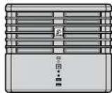
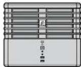
Rotating the Corsair Logo/Case Orientation: 9
Installing Top Fans: 10
Feet Installation and Case Orientation:....10
Congratulations!
Meet the Carbide Series Air 240 - an extraordinary small form factor PC case for Mini-ITX and MicroATX computers. The eye-catching cube design - complete with a full side window - hosts an internal layout optimized for maximum airflow or advanced watercooling configurations (including a 240mm radiator or two). Don't let the compact size fool you - this little one handles full size components while still offering roomy installation space.
Case SpecificationsTable of Contents
CARBIDE SERIES®
AIR240
SMALL FORM FACTOR PC CASE
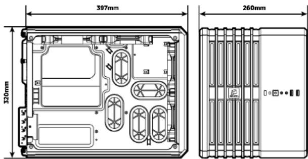
Length: 397mm
Width: 260mm
Height: 320mm
Weight: 5.6kg
Maximum GPU length:
No Front Fans: 360mm
Maximum CPU cooler height: 135mm
Maximum PSU length: 360mm
text_image
397mm 320mm 260mm
Air240
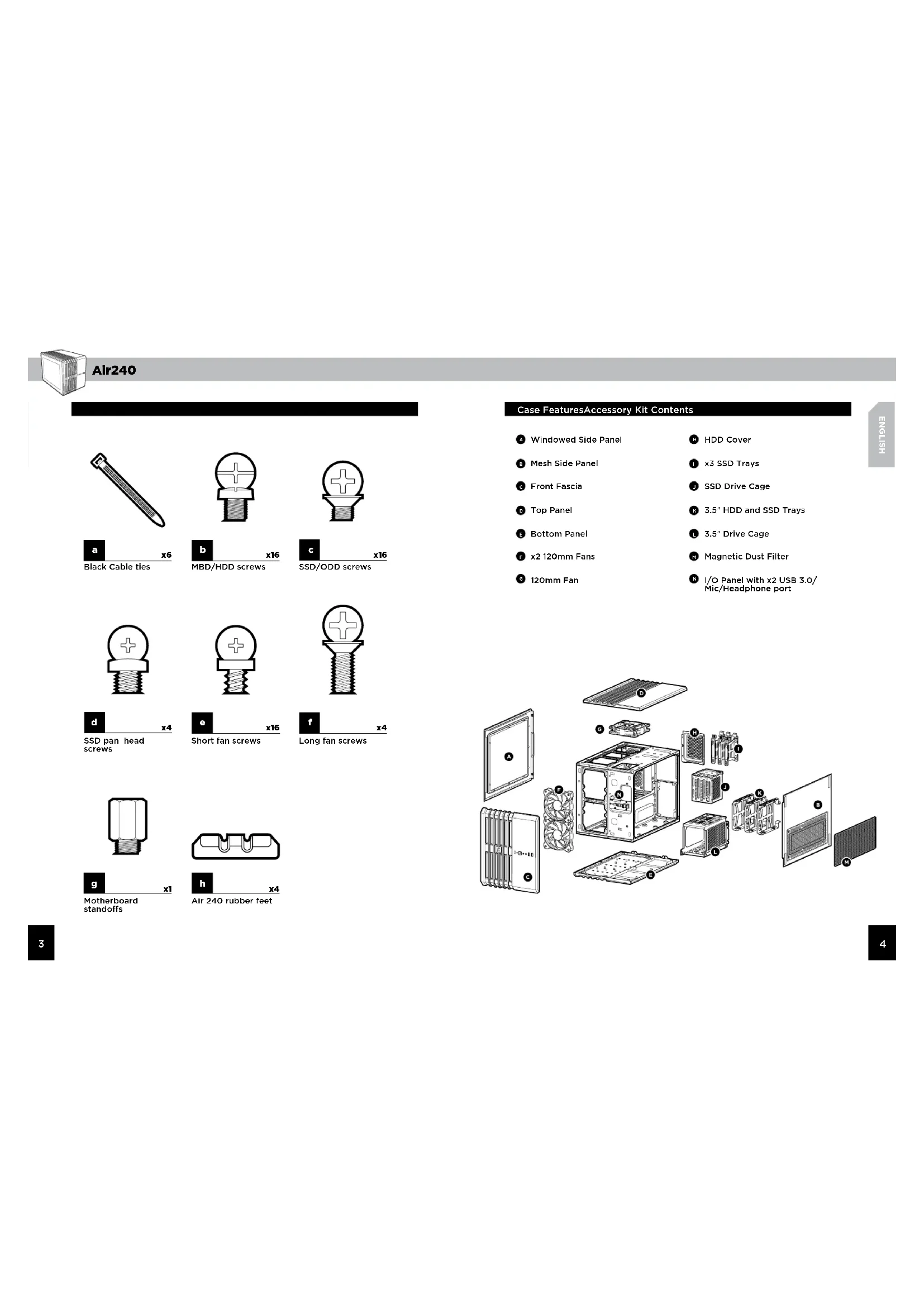
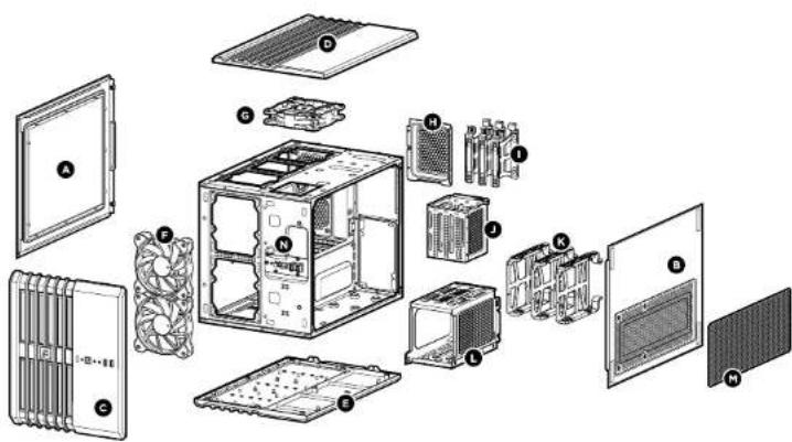
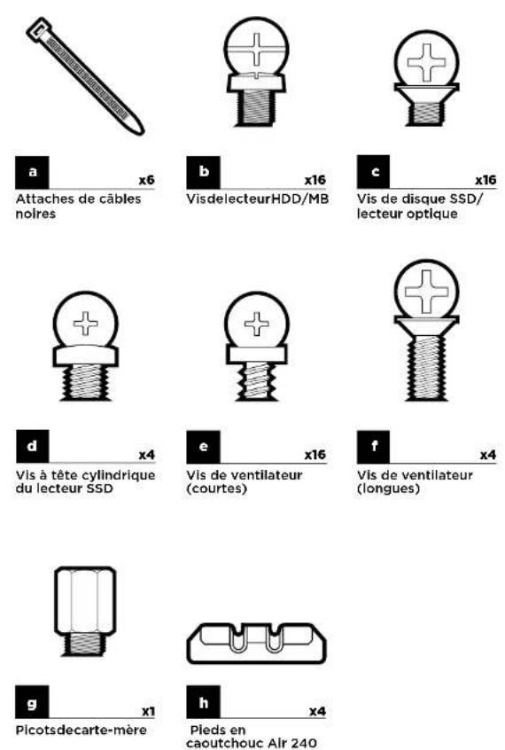
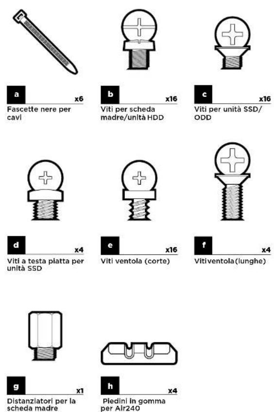
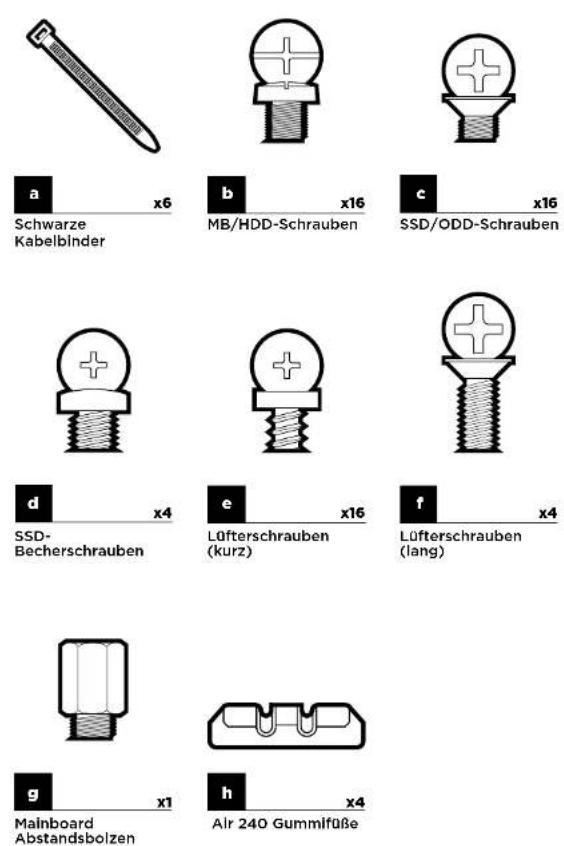
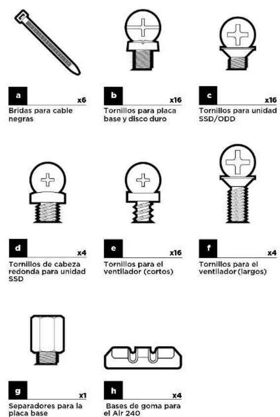
Case FeaturesAccessory Kit Contents
A Windowed Side Panel
Mesh Side Panel
Front Fascia
Top Panel
E Bottom Panel
F x2 120mm Fans
120mm Fan
H HDD Cover
1 x3 SSD Trays
J SSD Drive Cage
3.5" HDD and SSD Trays
3.5" Drive Cage
M Magnetic Dust Filter
N I/O Panel with x2 USB 3.0/Mic/Headphone port
text_image
Exploded view diagram of a computer system showing internal components like CPU, fans, and monitors with numbered labels.
SPEC-01
It's time to build a computer, but don't worry, we've done everything we can to make this stress-free. To begin, easily access the inside of the case by removing the rear thumbscrews and pulling out the side panel(s).
natural_image
Technical line drawing of an internal server rack unit with open door and internal panel (no text or symbols)2. Installing the Motherboard
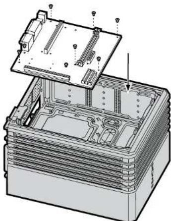
Insert the motherboard's I/O shield backplate into the case.
Before lowering the motherboard into the case, the motherboard mount holes and the case's hex-shaped standoffs (spacers) must align accordingly. The stand-offs are pre-mounted inside. You can twist and remove them if needed.
Anchor down the motherboard with the included motherboard screws.
natural_image
Technical illustration of an open electronic device casing with internal components and mounting holes (no text or symbols)3. Installing the PSU1. Removing the Side Panels
On the other side of the case, install the PSU under the drive bays and ensure the fan faces outward. Fasten screws to the rear of the PSU to secure its place in the case.
natural_image
Technical line drawing of a multi-chamber computer chassis with ventilation fans and ventilation ducts (no text or symbols)
SPEC-01
To install a SSD, first remove the two top rear thumbscrews and slide the cover off. Push the tab down to release and lift the cage, then insert your SSD into one of the available slots. The drive locks in once fully inserted into the cage. Reinsert the cage. Keep the case top off if you later plan to install fans here,
natural_image
Diagram of a computer tower with ventilation slots and a vertical rack, showing no text or symbols.5. Installing HDDs
Remove the top left fan grill and access the rear 3.5" HDD tray enclosure. Insert your HDD (or 2.5" SSD) into one of the open slots. Align the drive cage tray pins with the HDD mounting holes and click each pin into place. Insert the HDD tray enclosure back into the case.
natural_image
Technical line drawing of a computer tower case with internal components and an external housing (no text or symbols)6. Installing PCI-E/GPU4. Installing SSDs
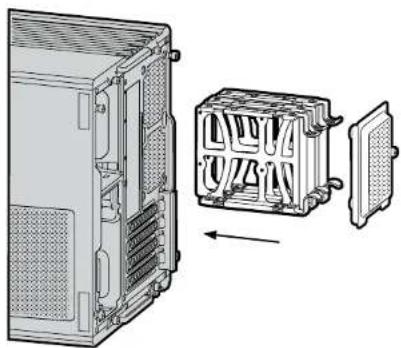
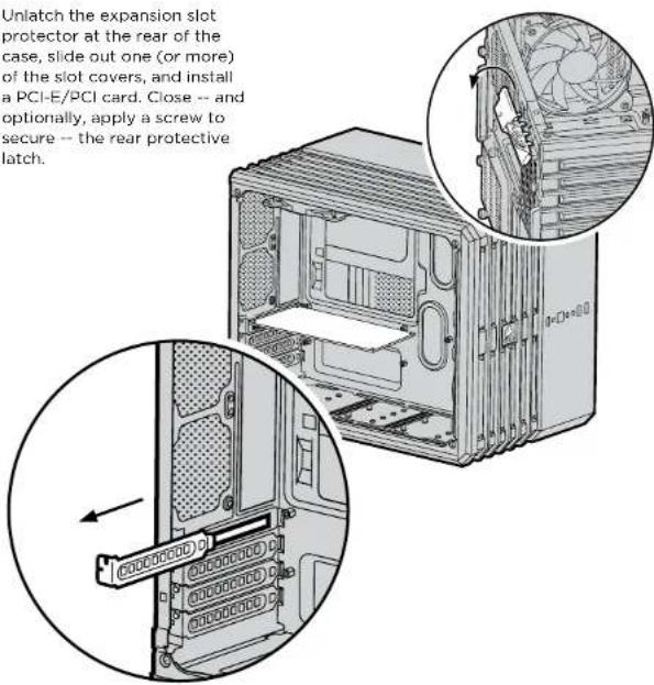
Unlatch the expansion slot protector at the rear of the case, slide out one (or more) of the slot covers, and install a PCI-E/PCI card. Close -- and optionally, apply a screw to secure -- the rear protective latch.
text_image
Unlatch the expansion slot protector at the rear of the case, slide out one (or more) of the slot covers, and install a PCI-E/PCI card. Close -- and optionally, apply a screw to secure -- the rear protective latch.
Air240
7. Installing Front Fans
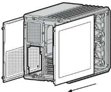
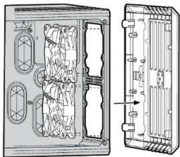
To install forward-facing fans, first remove the front panel. To do so, apply pressure to each side of the panel -- about an inch below the top, then repeat the same step an inch above the bottom - and slightly pull outwards. If the front panel doesn't remove easily after this process, it's still connected to the rest of the case; forcing the front panel free may cause damage. Insert fans and secure each fan with screws fastened through the front of the case. Align front panel and push it back into the case.
natural_image
Technical line drawing of a device rear panel with internal components and an external view showing internal structure (no text or symbols)8. Rotating the Corsair Logo/ Case Orientation
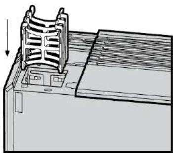
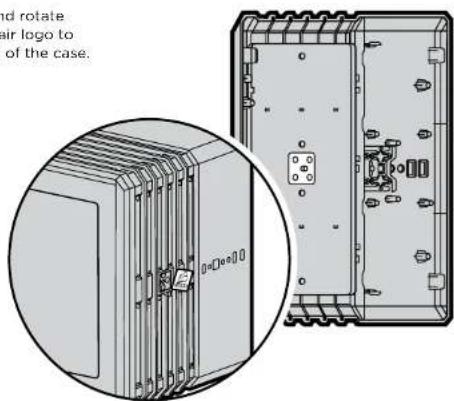
You can remove and rotate the magnetic Corsair logo to match the position of the case.
text_image
and rotate air logo to of the case.9. Installing Top Fans
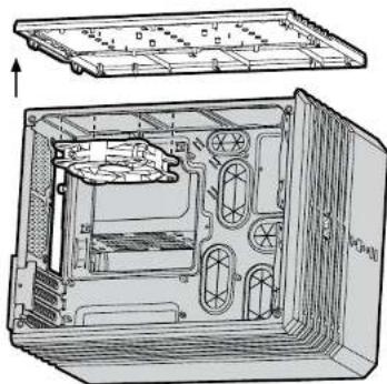
To install top fans, remove the top rear thumbscrews and slide the panel off. Insert fans and secure each fan with screws fastened through the top of the case. Slide the panel back on and refasten the rear top thumbscrews.
natural_image
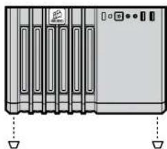
Technical line drawing of an open computer case with internal components and mounting brackets (no text or symbols)10. Feet Installation and Case Orientation
For enhanced stability, peel off the protective tape from the rubber feet and firmly affix each one to the bottom case corners. The location can vary depending on how the case is positioned.
natural_image
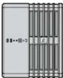
Front view of a server rack unit with ventilation slots and indicator lights (no text or symbols visible)
natural_image
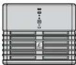
Four technical line drawings of server rack units with no visible text or symbols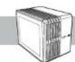
Air240
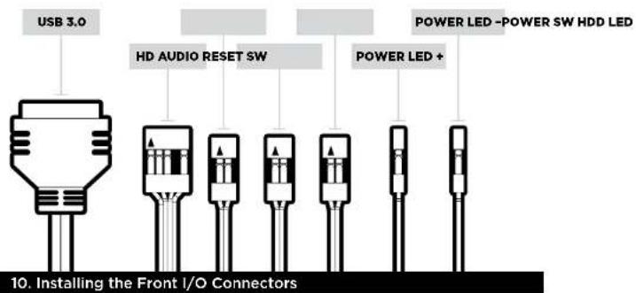
11. Installing the Front I/O Connectors
After locating your 3 or 4 pin fan headers on your motherboard (see your motherboard's manual for fan header locations), plug in the included fan cable.
text_image
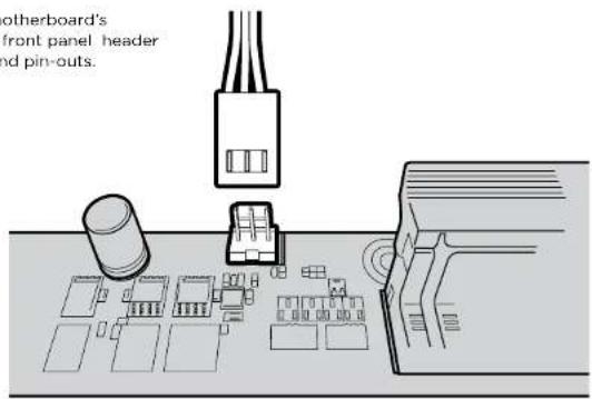
USB 3.0 HD AUDIO RESET SW POWER LED -POWER SW HDD LED POWER LED + 10. Installing the Front I/O ConnectorsSee your motherboard's manual for front panel header locations and pin-outs.
text_image
otherboard's front panel header and pin-outs.Frequently Asked Questions
- Does the polarity matter with the I/O panel's power and reset header? No, only the LED headers.
- Who should I contact if I received my case damaged or one of the fans is no longer working? Please go to corsair.force.com and request an RMA so that we can replace the damaged part(s)
Air240
Félicitations: 13
text_image
397mm 320mm 260mm
Air240
text_image
Exploded view diagram of a computer system showing internal components like CPU, fans, and heat sinks with numbered labels.
Air240
natural_image
Technical line drawing of an internal server or rack unit with open door and internal panel (no text or symbols)natural_image
Technical illustration of an open hard drive chassis with internal components and mounting holes (no text or symbols)natural_image
Technical line drawing of a multi-chamber computer chassis with ventilation fans and ventilation ducts (no text or symbols)
Air240
natural_image
Diagram of a computer tower with ventilation slots and a vertical rack, showing no text or symbols.5. Installation des HDD
natural_image
Technical line drawing of a computer tower case with internal components and an external housing (no text or symbols)natural_image
Technical line drawing of a computer tower case with an inset showing internal fan structure (no text or symbols)
Air240
natural_image
Technical line drawing of a device rear panel showing internal components and a side view with an arrow indicating assembly or connection (no text or symbols present)natural_image
Technical line drawing of an internal device housing with visible internal components and mounting brackets (no text or symbols)natural_image
Front view of a server rack unit with multiple ventilation grilles and indicator lights (no visible text or labels)
natural_image
Four technical line drawings of electronic device modules with no visible text or symbols
Air240
text_image
397mm 320mm 260mm
Air240
text_image
Exploded view diagram of a computer system showing internal components like CPU, fans, and heat sinks with numbered labels.
Air240
natural_image
Technical line drawing of an internal device housing with ventilation grilles and ventilation ducts (no text or symbols)natural_image
Technical illustration of an open stacked electronic device with internal components and mounting holes (no text or symbols)natural_image
Technical line drawing of a multi-chamber computer chassis with ventilation fans and ventilation grilles (no text or symbols)
Air240
natural_image
Technical line drawing of a computer tower with ventilation slots and a load arrow (no text or symbols)natural_image
Technical line drawing of a computer tower case with internal components and an external housing (no text or symbols)natural_image
Technical line drawing of a mechanical or electronic device interior with no visible text or symbols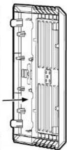
natural_image
Technical line drawing of a mechanical component with internal channels and mounting holes (no text or symbols)natural_image
Technical line drawing of an internal device casing with visible internal components and mounting brackets (no text or symbols)natural_image
Front view of a server rack unit with indicator lights and ventilation slots (no text or symbols visible)

Alr240
text_image
397mm 320mm 260mm
Air240
text_image
Exploded view diagram of a computer system showing internal components like CPU, fans, and heat sinks with numbered labels.
Air240
natural_image
Technical line drawing of an internal server or rack unit with open door and internal panel (no text or symbols)2. Installation des Mainboards
natural_image
Technical illustration of an open electronic device casing with internal components and mounting hardware (no text or symbols)natural_image
Technical line drawing of a multi-chamber computer chassis with ventilation fans and ventilation ducts (no text or symbols)
Air240
natural_image
Diagram of a computer tower with ventilation slots and a vertical rack, showing no text or symbols.5. HDDs installieren
natural_image
Technical line drawing of a computer tower case with internal components and an external housing (no text or symbols)6. PCI-E/GPU installieren4. SSDs installieren
natural_image
Technical line drawing of a mechanical or electrical enclosure with internal components and mounting holes (no text or symbols)
natural_image
Technical line drawing of a rectangular electronic component with internal channels and mounting holes (no text or symbols)natural_image
Technical line drawing of an internal device housing with visible internal components and mounting brackets (no text or symbols)natural_image
Front view of a server rack unit with multiple ventilation grilles and indicator lights (no visible text or labels)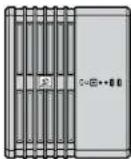


Air240
text_image
397mm 320mm 260mm
Air240
text_image
Exploded view diagram of a computer system with labeled components including CPU, fan, and monitor
Air240
natural_image
Technical line drawing of an internal device housing with ventilation grilles and ventilation ducts (no text or symbols)natural_image
Technical illustration of an open stacked electronic device casing with internal components and mounting hardware (no text or symbols)natural_image
Technical line drawing of a multi-chamber computer chassis with ventilation fans and ventilation grilles (no text or symbols)
Air240
natural_image
Technical line drawing of a computer tower with ventilation slots and a load arrow (no text or symbols)natural_image
Technical line drawing of a computer tower case with internal components and an external housing (no text or symbols)natural_image
Technical line drawing of a computer tower case with an inset showing internal fan structure (no text or symbols)
Air240
natural_image
Technical line drawing of a device rear panel showing internal components and housing structure (no text or symbols)natural_image
Technical illustration of an electronic device showing internal components and a close-up view (no text or symbols)natural_image
Technical line drawing of an internal computer case with visible internal components and mounting brackets (no text or symbols)natural_image
Front view of a server rack unit with multiple ventilation grilles and indicator lights (no visible text or labels)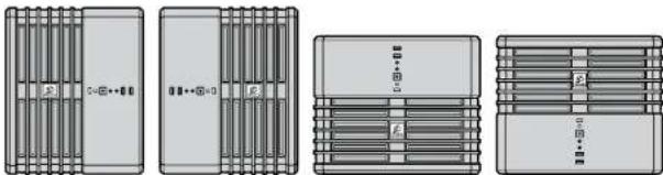
natural_image
Four technical line drawings of server rack units with no visible text or symbols
Air240
text_image
397mm 320mm 260mm
Air240
natural_image
Technical line drawing of an internal device housing with ventilation grilles and ventilation ducts (no text or symbols)natural_image
Technical illustration of an open stacked electronic device with internal components and mounting holes (no text or symbols)natural_image
Technical line drawing of a multi-chamber computer chassis with visible fan and ventilation slots (no text or labels)
Air240
natural_image
Diagram of a computer tower with ventilation slots and a vertical rack, showing no text or symbols.natural_image
Technical line drawing of a computer tower case with internal components and an external housing (no text or symbols)natural_image
Technical line drawing of a computer tower case with an inset showing internal components (no text or symbols)
Air240
natural_image
Technical line drawing of a device rear panel showing internal components and a side view with an arrow indicating assembly or connection (no text or symbols present)natural_image
Technical line drawing of an internal computer case with visible internal components and mounting brackets (no text or symbols)natural_image
Front view of a server rack unit with multiple ventilation grilles and indicator lights (no visible text or labels)
natural_image
Four technical line drawings of server rack units with no visible text or symbols
Air240
text_image
397mm 320mm 260mm
Air240

机箱特点配件目录
text_image
Exploded view diagram of a computer system with labeled components in Chinese
Air240
natural_image
Technical line drawing of an internal server or rack unit with visible fan and ventilation slots (no text or symbols)2. 安装母板
natural_image
Exploded view diagram of an internal electronic device showing internal components and mounting points (no text or labels)3. 安装 PSU1. 拆卸侧面板
natural_image
Technical line drawing of a multi-chamber computer chassis with visible fan and ventilation slots (no text or labels)
Air240
natural_image
Diagram of a computer tower with ventilation slots and a vertical rack, showing no text or symbols.5. 安装 HDD
natural_image
Technical line drawing of a computer tower case with internal components and an external housing (no text or symbols)natural_image
Technical line drawing of a device rear panel showing internal components and housing structure (no text or symbols)natural_image
Technical line drawing of an open computer case with internal components and ventilation slots (no text or symbols)10. 安装支脚和调整机箱朝向
natural_image
Front view of a server rack unit with multiple ventilation grilles and indicator lights (no visible text or labels)
natural_image
Four technical line drawings of server rack units with no visible text or symbols
Air240
11. 安装前面 I/O 连接器
text_image
397mm 320mm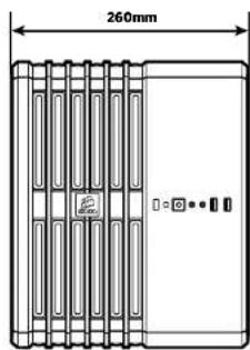
text_image
260mm
Air240
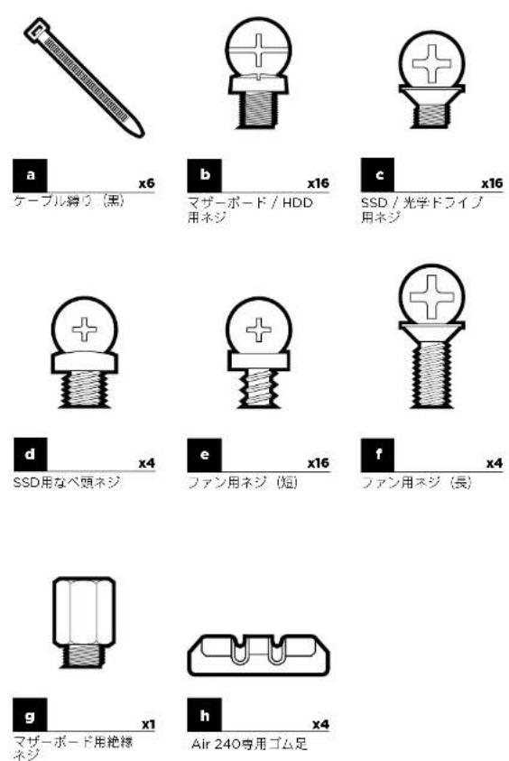
ケースの特徴アクセサリーキットの内容
text_image
Exploded view diagram of a computer system showing internal components like CPU, heatsink, and fan assembly
Air240
natural_image
Technical line drawing of an internal server or rack unit with visible fan and ventilation slots (no text or symbols)2 マザーボードを取り付ける
natural_image
Technical illustration of an open hard drive chassis with internal components and mounting hardware (no text or symbols)natural_image
Technical line drawing of a multi-chamber computer chassis with ventilation fans and ventilation grilles (no text or symbols)
Air240
natural_image
Diagram of a computer tower with ventilation slots and a vertical load arrow (no text or symbols)5. HDDの取り付け
natural_image
Technical line drawing of a computer tower case with internal components and an external housing (no text or symbols)natural_image
Technical line drawing of a computer tower case with internal components and an inset close-up showing internal fan blades (no text or symbols)
Air240
7. フロントファンの取り付け
natural_image
Technical line drawing of a device rear panel showing internal components and housing structure (no text or symbols)natural_image
Technical line drawing of an internal hard drive or chassis assembly (no text or symbols visible)natural_image
Front view of a server rack unit with indicator lights and ventilation slots (no text or symbols visible)
natural_image
Four technical line drawings of server rack units with no visible text or symbols