Carbide SPECM2 - Desktop Computer CORSAIR - Free user manual and instructions
Find the device manual for free Carbide SPECM2 CORSAIR in PDF.
User questions about Carbide SPECM2 CORSAIR
0 question about this device. Answer the ones you know or ask your own.
Ask a new question about this device
Download the instructions for your Desktop Computer in PDF format for free! Find your manual Carbide SPECM2 - CORSAIR and take your electronic device back in hand. On this page are published all the documents necessary for the use of your device. Carbide SPECM2 by CORSAIR.
USER MANUAL Carbide SPECM2 CORSAIR
natural_image
Line drawing of a desktop computer tower case with ventilation slots and ventilation duct (no text or symbols)CARBIDE SERIES*

CORSAIR
47100 Bayside Parkway • Fremont • California • 94538 • USA | corsair.com
© 2015 Corsair Components, Inc.
All rights reserved. Corsair, the sails logo, and Carboide Series are registered trademarks of Corsair in the United States and/or other countries. All other trademarks are the property of their respective owners. Product may vary slightly from those pictured.
PN: 49-001433 rev AA


text_image
SPEC-M2
INSTALLATION GUIDE ■ GUIDE D'INSTALLATION
INSTALLATIONSANLEITUNG ■ Guía de instalación
РУКОВОДСТВО ПО УСТАНОВКЕ ■ GUIA DE INSTALAÇÃO
インストールガイド
English: 5-14
Français: 15-24
Deutsch: 25-34
Español: 35-44
Россию: 45-54
Português: 55-64
日本人:65-74

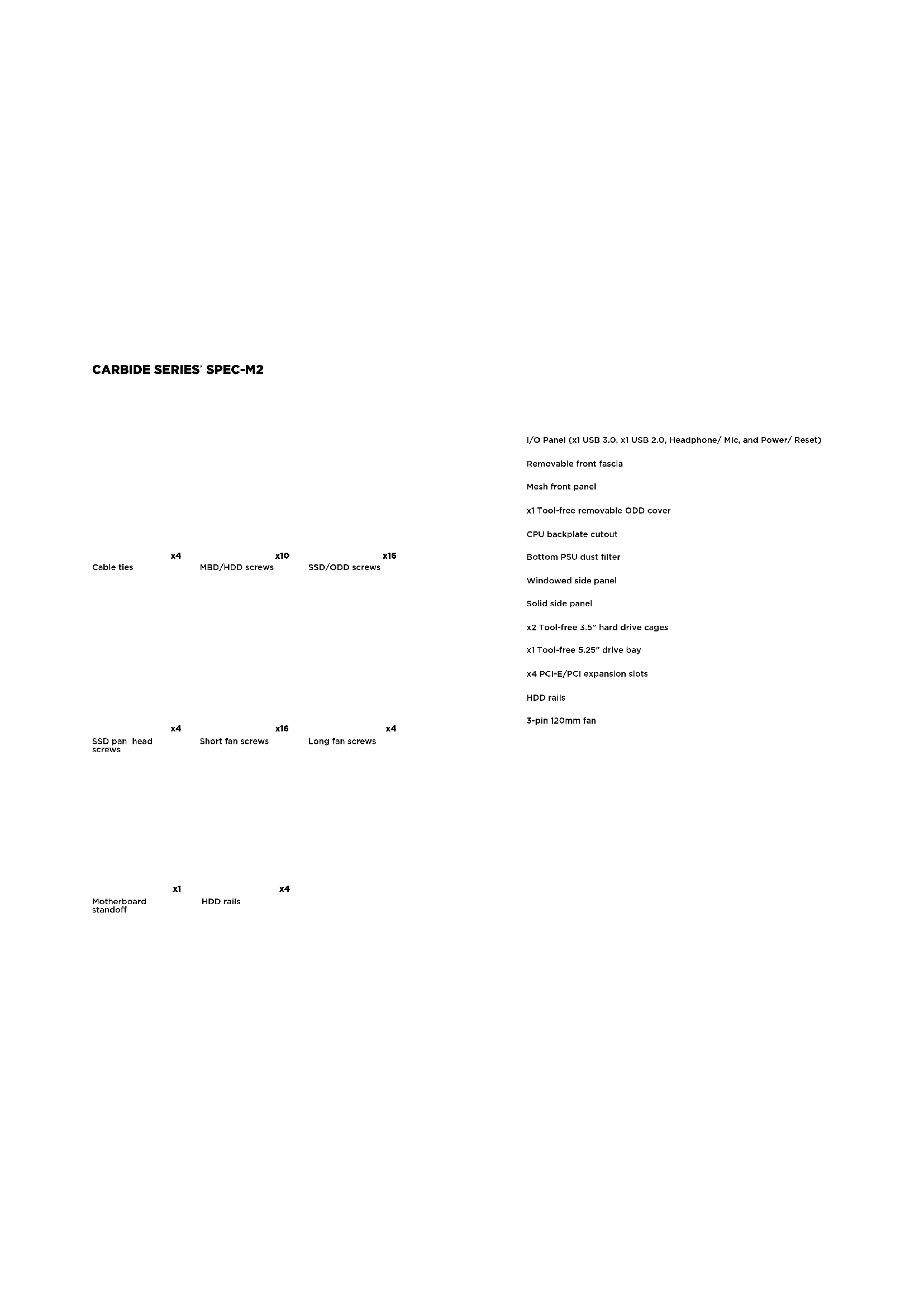
CARBIDE SERIES SPEC-M2
Table of Contents Case Specifications
Congratulations: 5
Case specifications: 6
Accessory kit contents: 7
Case features: 8
Removing the side panels: 9
Installing the motherboard: 9
Installing PCI-E/PCI card(s): 10
Installing the power supply: 10
Removing the front fascia:....11
Installing an ODD: 11
Installing HDDs: 12
Installing SSDs: 12
Powering the case fans: 13
Installing the front I/O connectors: 13
Frequently asked questions: 14
Congratulations!
Thank you for purchasing the
Carbide Series SPEC-M2 Micro-ATX Gaming Case.
The Carbide Series SPEC-M2 Micro ATX Gaming Case is built with performance in mind. A mesh front intake and 120mm LED fan pushes cool air across your graphics card and CPU, and room for up to five fans total and native support for SSDs mean your next system will be easily upgraded when you want it to be.
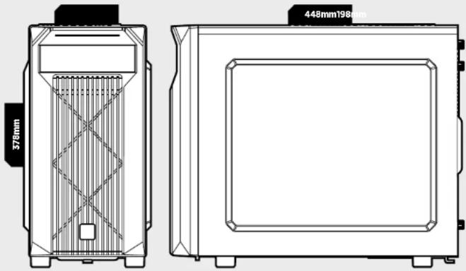
Length: 448mm
Width: 198mm
Height: 378mm
Weight: 4.6kg
Maximum GPU length: 383mm
Maximum CPU cooler height: 150mm
Maximum PSU length: 160mm
natural_image
Technical line drawing of a device casing with internal grid structure and measurement annotations (no readable text or symbols)CARBIDE SERIES® SPEC-M2
| x4 | x10 | x16 | |
| Cable ties | MBD/HDD screws | SSD/ODD screws | |
| x4 | x16 | x4 | |
| SSD pan head screws | Short fan screws | Long fan screws |
| x1 | x4 | |
| Motherboard standoff | HDD rails | |
I/O Panel (x1 USB 3.0, x1 USB 2.0, Headphone/ Mic, and Power/ Reset)
Removable front fascia
Mesh front panel
x1 Tool-free removable ODD cover
CPU backplate cutout
Bottom PSU dust filter
Windowed side panel
Solid side panel
x2 Tool-free 3.5" hard drive cages
x1 Tool-free 5.25" drive bay
x4 PCI-E/PCI expansion slots
HDD rails
3-pin 120mm fan

CARBIDE SERIES SPEC-M2
1. Removing the Side Panels
Simply remove the
thumbscrews then slide the side panels back and out.
Note: Corsair recommends
removing both side panels and setting them aside when building your system to avoid accidental damage. Both side panels are interchangeable and should be removed to reduce clutter.
text_image
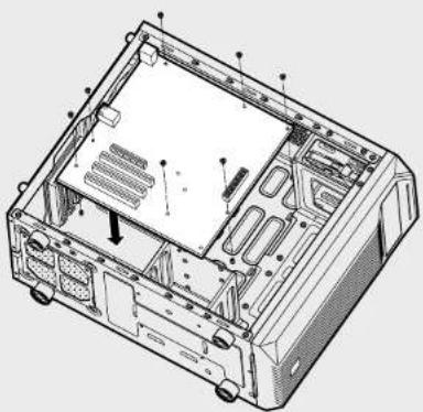
Technical diagram of an open computer case with numbered annotations pointing to internal components2. Installing the Motherboard
First, install your
motherboard's I/O shield
(see your motherboard's
manual for guidance)
Align your motherboard with the pre-installed standoffs.
Use the provided screws
to secure the
motherboard to the
motherboard tray.
natural_image
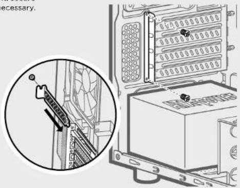
Technical line drawing of an internal computer chassis showing casing, drive bays, and ventilation slots (no text or labels)3. Installing PCI-E/PCI Card(s)
Remove slot cover, install
expansion card, and secure with screw(s) as necessary.
text_image
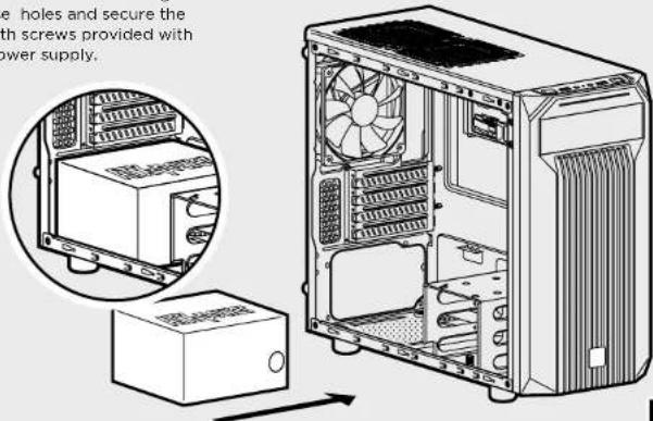
necessary.4. Installing the Power Supply
Position the PSU on the
bottom of the case then align
the case holes and secure the
PSU with screws provided with your power supply.
text_image
e holes and secure the with screws provided with power supply.
CARBIDE SERIES SPEC-M2
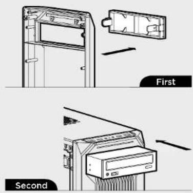
5. Removing the Front Fascia
To remove the front fascia (front panel), grasp the tab located at the bottom fascia and pull outward.
natural_image
Technical line drawing of a computer chassis with internal components and mounting holes (no text or symbols)6. Installing an ODD (Optical Disk Drive)
First, remove the front panel 5.25" drive bay cover then slide the ODD into the drive bay until the tool-free latch clicks, securing the drive. To release an optical drive, push in the tool-free tab then pull the drive outward.
text_image
First Second7. Installing HDDs
Step 1 - Clamp the side rails to the drive, with prongs and drive connectors facing the same way.
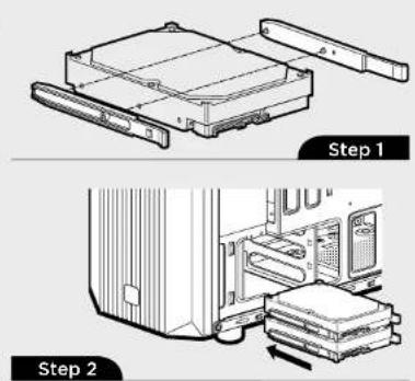
text_image
Step 1 Step 2Step 2 - Slide the drive and rail assembly into the HDD cage from behind the motherboard as shown.
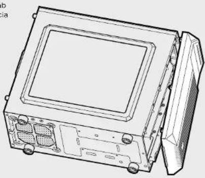
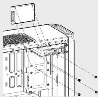
8. Installing SSDs
Insert an SSD into the mounting tray and attach with screws as shown.
natural_image
Technical line drawing of a computer tower with visible internal components and mounting holes (no text or labels)
CARBIDE SERIES SPEC-M2
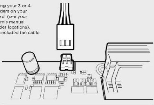
9. Powering the Case Fans
After locating your 3 or 4 pin fan headers on your motherboard (see your motherboard's manual for fan header locations), plug in the included fan cable.
text_image
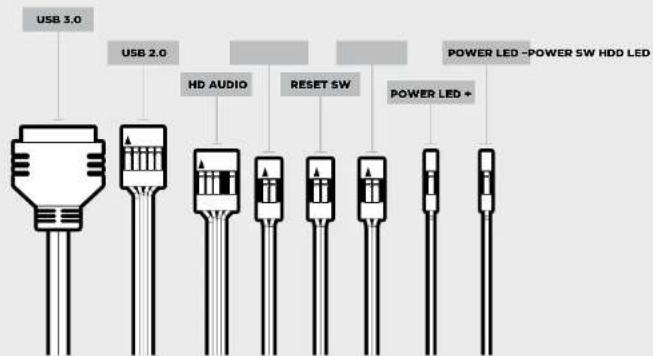
ng your 3 or 4 ders on your rd. (see your rd's manual der locations). included fan cable.10. Installing the Front I/O Connectors
See your motherboard's manual for front panel header locations and pin-outs.
text_image
USB 3.0 USB 2.0 HD AUDIO RESET SW POWER LED - POWER SW HDD LED POWER LED +Frequently Asked Questions
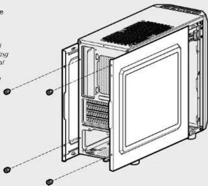
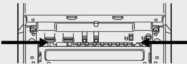
- How do I remove the I/O Panel?
If needed, you can uninstall your I/O panel by removing the front fascia (step 5) then unscrewing the 2 screws at each side of panel. (see drawing)
natural_image
Technical line drawing of a mechanical or electronic component assembly (no text or symbols visible)-
Does the polarity matter with the I/O panel's power and reset header? No, only the LED headers.
-
Who should I contact if I received my case damaged or one of the fans is no longer working? Please go to corsair.force.com and request an RMA so that we can replace the damaged part(s).
-
Where can I mount a fan?
| Fan Mount Locations | |
| Front x2 120mm (1 included) | |
| Top x2 120mm | |
| Rear x1 120mm | |
| Bottom x | |
| Side x | |
| Mid x | |
To learn more about this case visit the product page at corsair.com

CARBIDE SERIES SPEC-M2
Foire aux questions: 24
Félicitations!
natural_image
Technical line drawing of a device casing with internal grid structure and measurement annotations (no readable text or symbols)
CARBIDE SERIES SPEC-M2
text_image
Exploded view diagram of a desktop computer system with labeled components
CARBIDE SERIES SPEC-M2
text_image
Technical diagram of a computer case with labeled components and annotations in Chinesenatural_image
Technical line drawing of an internal computer chassis showing casing, drive bays, and ventilation slots (no text or labels)3. Installation des cartes PCI-E/PCI
Retirez les caches
text_image
Technical diagram showing a mechanical assembly with a magnified inset highlighting a component detail.natural_image
Technical line drawing of a device chassis with internal components and mounting holes (no text or symbols)natural_image
Technical line drawing of a computer tower with visible internal components and mounting points (no text or symbols)
CARBIDE SERIES® SPEC-M2
natural_image
Technical line drawing of a mechanical or electronic component with no visible text or symbolstext_image
378mm 448mm198mm
CARBIDE SERIES SPEC-M2
text_image
Exploded view diagram of a desktop computer system with labeled components from fan to tower
CARBIDE SERIES SPEC-M2
natural_image
Technical line drawing of an internal computer chassis showing casing, drive bays, and ventilation slots (no text or labels)text_image
Technical diagram showing a mechanical assembly with a magnified inset highlighting a component detail.natural_image
Technical line drawing of a device chassis with internal components and mounting holes (no text or symbols)natural_image
Technical line drawings of two mechanical components, Schritt 1 and Schritt 2, showing internal assembly and mounting details (no text or symbols)natural_image
Technical line drawing of a computer tower with visible internal components and mounting points (no text or symbols)
CARBIDE SERIES SPEC-M2
Motherboards (die Position
natural_image
Technical line drawing of a mechanical or electronic component assembly (no text or symbols visible)natural_image
Technical line drawing of a device casing with internal structure and dimension annotations (no readable text or symbols)
CARBIDE SERIES SPEC-M2
text_image
Exploded view diagram of a desktop computer system with labeled components from fan to monitor
CARBIDE SERIES SPEC-M2
text_image
Technical diagram of an internal computer case with numbered annotations pointing to different components.natural_image
Technical line drawing of an internal computer chassis showing casing, drive bays, and ventilation slots (no text or labels)natural_image
Technical line drawing of a computer chassis with visible internal components and mounting holes (no text or symbols)natural_image
Technical line drawing of a computer tower with visible internal components and mounting points (no text or symbols)
CARBIDE SERIES SPEC-M2
natural_image
Technical line drawing of a mechanical or electronic component assembly (no text or symbols visible)| Fan Mount Locations | |
| Parte delantors x2 120mm (1 included) | |
| Parte superior x2 120mm | |
| Posterior x1 120mm | |
| Parte inferior x | |
| Lateral x | |
| Parte central x | |
natural_image
Technical line drawing of a device casing with internal grid structure and measurement annotations (no readable text or symbols)
CARBIDE SERIES SPEC-M2
text_image
Exploded view diagram of a desktop computer system with labeled components
CARBIDE SERIES SPEC-M2
text_image
Technical diagram of a computer oven with labeled components and Chinese annotationsnatural_image
Technical line drawing of an internal computer chassis showing casing, drive bays, and ventilation slots (no text or labels)3. Установка плат PCI-E/PCI
natural_image
Technical line drawing of a computer case with internal components and mounting holes (no text or symbols)natural_image
Technical line drawing of a computer tower with visible internal components and mounting points (no text or symbols)
CARBIDE SERIES SPEC-M2
natural_image
Technical line drawing of a mechanical or electronic component with no visible text or symbolsnatural_image
Technical line drawing of a device casing with internal grid structure and measurement annotations (no readable text or symbols)
CARBIDE SERIES SPEC-M2
text_image
Exploded view diagram of a desktop computer system with labeled components from fan to tower
CARBIDE SERIES SPEC-M2
natural_image
Technical line drawing of an internal computer chassis showing casing, drive bays, and ventilation slots (no text or labels)3. Instalando a(s) placa(s) PCI-E/PCI
text_image
Technical diagram showing a device panel with a close-up inset highlighting a cable or connector detail.natural_image
Technical line drawing of a computer chassis with front panel and internal components (no text or symbols)natural_image
Technical line drawing of a computer tower with visible door, ventilation slots, and mounting bracket (no text or labels)
CARBIDE SERIES® SPEC-M2
natural_image
Technical line drawing of a mechanical or electronic component assembly (no text or symbols visible)natural_image
Technical line drawing of a device casing with internal structure and measurement annotations (378mm and 448mm)
CARBIDE SERIES SPEC-M2
アクセサリーキットの内容
a x4
ケーブル結束バンド
text_image
Exploded view diagram of a desktop computer system with labeled components from fan to monitor
CARBIDE SERIES SPEC-M2
1. サイドパネルの取り外し
text_image
Technical diagram of a computer tower case with labeled components in Chinese2. マザーボードの取り付け
natural_image
Technical line drawing of an internal computer case with visible components and mounting holes (no text or labels)text_image
Technical diagram showing a cable connector inserted into an internal unit with a magnified inset highlighting the component's structure.4. 電源ユニットの取り付け
natural_image
Technical line drawing of a device housing with internal components and mounting holes (no text or symbols)6. 光学ドライブの取り付け
natural_image
Technical line drawing of a mechanical housing assembly with no visible text or symbolsnatural_image
Diagram of a computer setup showing an open drive and stacked books (no text or symbols visible)8. SSD の取り付け
natural_image
Technical line drawing of a computer tower with visible internal components and mounting bracket (no text or symbols)