
HD 13124 St - Pressure washer Kärcher - Free user manual and instructions
Find the device manual for free HD 13124 St Kärcher in PDF.



| Brand | Kärcher |
| Model | HD 13/12-4 ST |
| Product type | Fixed high pressure cleaner (wash station) |
| Power supply | 400 V / 3~ / 50-60 Hz |
| Connected power | 7,3 kW |
| Electrical protection | IPX5, circuit breaker 16 A (delayed action) |
| Operating pressure | 3 - 12 MPa (30 - 120 bar) |
| Maximum pressure | 15 MPa (150 bar) |
| Flow rate | 650 - 1300 l/h (10,8 - 21,7 l/min) |
| Maximum supply temperature | 70 °C (ST), 85 °C (ST-H) |
| Maximum supply pressure | 1,0 MPa (10 bar) |
| Nozzle | Triple nozzle EASY!Lock (0°/CHEM/25°) |
| Detergent dosing system | Low-pressure injector with dosing valve (0-6%) |
| Oil tank capacity | 1,25 L (SAE 90 Hypoid) |
| Dimensions (L x H x P) | 533 x 790 x 420 mm |
| Weight | 78 kg (basic unit ST) |
| Mounting | Wall or on frame (option) |
| Water connection | 3/4" female |
| High pressure connection | EASY!Lock |
| Safety | Pressure switch, discharge valve, thermal circuit breaker, flexible anti-rupture safety, leak monitoring, emergency stop (option) |
| Features | Automatic start/stop, adjustable standby time (5-120 min), frost protection, water softener system (option) |
| Included accessories | EA-SY!Force gun, steel lance, triple nozzle, 10 m high pressure hose (approx.) |
| Warranty | According to country conditions (see manual) |
Frequently Asked Questions - HD 13124 St Kärcher
User questions about HD 13124 St Kärcher
0 question about this device. Answer the ones you know or ask your own.
Ask a new question about this device
Download the instructions for your Pressure washer in PDF format for free! Find your manual HD 13124 St - Kärcher and take your electronic device back in hand. On this page are published all the documents necessary for the use of your device. HD 13124 St by Kärcher.
USER MANUAL HD 13124 St Kärcher
natural_image
Exterior view of a KARCHER Professional water heater (no visible text or symbols on the device body)Register and win! www.kaercher.com/register-and-win

EAC


59676630 01/17
text_image
Technical diagram of an electrical enclosure with numbered components and safety warning labelstext_image
Technical diagram of a mechanical assembly with numbered components and labeled partstext_image
Technical diagram showing two mechanical assembly steps with numbered components and directional arrows indicating assembly direction.natural_image
Line drawing of a sewing machine with scissors and base mount (no text or symbols)natural_image
Diagram of a mechanical device with a knob and arrow indicating motion (no text or symbols)71364 Winnenden (Germany)
Tel.: +49 7195 14-0
Fax: +49 7195 14-2212
Winnenden, 2016/11/01
Please read and comply with these original instructions prior
to the initial operation of your appliance and store them for later use or subsequent owners.
Before first start-up it is definitely necessary to read the safety indications Nr. 5.956-309.0!
Contents
Environmental protection.....EN 1
Safety instructions ..... EN 1
Proper use.....EN 2
Function.....EN 3
Device elements ..... EN 4
Operation.....EN 4
Transport....EN 5
Storing the device ..... EN 5
Care and maintenance ..... EN 5
Troubleshooting.....EN 8
Technical specifications.....EN 9
Accessories ..... EN 11
Installing the plant ..... EN 13
EU Declaration of Conformity. EN 14
Accessories and Spare Parts . EN 14
Warranty ..... EN 14
Customer Service ..... EN 15
Environmental protection

The packaging material can be recycled. Please do not throw the packaging material into household waste; please send it for recycling.

Old appliances contain valuable materials that can be recycled; these should be sent for recycling. Batteries, oil, and similar substances must not enter the environment. Please dispose of your old appliances using appropriate collection systems.
Please do not release engine oil, fuel oil, diesel and petrol into the environment Protect the ground and dispose of used oil in an environmentally-clean manner.
Notes about the ingredients (REACH)
You will find current information about the ingredients at:
www.kaercher.com/REACH
Safety instructions
- Please follow the national rules and regulations for fluid spray jets of the respective country.
- Please follow the national rules and regulations for accident prevention of the respective country. Fluid spray jets must be tested regularly and the results of these tests must be documented in writing.
- Please follow the safety instructions which are attached to the used detergents (normally on the packing label).
– The device may only be installed by a specialized company according to the national regulations.
- The appliance may only be connected to an electrical supply which has been installed by an electrician in accordance with IEC 60364.
- If the power cord is damaged, please arrange immediately for the exchange by an authorized customer service or a skilled electrician.
- First remove the mains plug before doing any job on the device
- Power plug and receptacle must be freely accessible after the installation.
- The plant must be secured through a wrong current protection switch with a triggering current lesser than or equal to 30mA .
- The appliance may only be used by persons who have been instructed in handling the appliance or have proven qualification and expertise in operating the appliance or have been explicitly assigned the task of handling the appliance.
- The appliance must not be operated by children, young persons or persons who have not been instructed accordingly.
Symbols on the machine

High-pressure jets can be dangerous if improperly used. The
jet may not be directed at persons, animals, live electrical equipment or at the appliance itself.
Risk of burns on account of hot surfaces!

Risk of injury! Beware of dangerous electrical current.

Hazard levels
△DANGER
Pointer to immediate danger, which leads to severe injuries or death.
⚠ WARNING
Pointer to a possibly dangerous situation, which can lead to severe injuries or death.
△CAUTION
Pointer to a possibly dangerous situation, which can lead to minor injuries.
ATTENTION
Pointer to a possibly dangerous situation, which can lead to property damage.
Work-stations
The unit is turned on and off only at the pump unit. Depending on the plant installation, the work-stations are located at the accessories (spraying units) connected to the feeder points.
Personal safety gear

Wear ear plugs to protect your ears against hearing loss while cleaning parts that produce high sound levels.
Wear protective clothing and safety goggles to protect against splash back containing water or dirt.
Safety Devices
Safety devices serve to protect the user and must not be rendered in operational or their functions bypassed.
Power switch
The switch prevents unintended starting of the appliance. Stop the appliance during breaks or after operation.
Safety catch
The safety catch on the trigger gun prevents the appliance from being switched on unintentionally.
Overflow valve with pressure switch
- While reducing the water supply/quantity regulation at the pump head, the overflow valve opens and part of the water flows back to the pump suck side.
- If the lever on the trigger gun is released the pressure switch turns off the pump, the high pressure jet is stopped. If the lever is pulled the pump is turned on again.
The overflow valve and pressure switch are set and sealed at the factory. Setting only by customer service.
Winding protection contact
The winding protection contact in the motor winding of the pump drive switches off the engine when there is a thermal overload. (With HD 13/12-4 ST only...).
Operational readiness period
If the appliance is not used for an extended period of time (adjustable 5...120 minutes), the appliance will shut off.
Hose break protection
If the operating time (without interruption of work) exceeds an adjustable value (5...120 minutes), the appliance will shut off.
Motor protection switch
The motor protection switch switches off the device if the power consumption is high.
Leakage monitoring
In case of leaks in the high pressure system, the appliance is shut off.
Pressure relief (option)
After the operation readiness period, a solenoid valve opens in the high pressure system and relieves the pressure.
Lack of water fuse (option)
The lack of water fuse in the float container prevents the high pressure pump from running dry in case of a lack of water.
Proper use
- This equipment produces water under high pressure downstream to high pressure cleaning devices. If required the detergent is drawn in and added to the water.
- The high pressure module is permanently installed in a dry, frost-free room. The high pressure water is distributed through a fixed network of pipes. Alternatively, a hand spray gun with a high pressure hose can be connected directly to the high pressure outlet of the appliance.
- The high pressure model must be installed at a wall in such a way that the rear opening is sealed by the wall.
△DANGER
Risk of injury! Follow the respective safety regulations when operating at gas stations or other dangerous areas.
Please do not let mineral oil contaminated waste water reach soil, water or the sewage system. Perform engine cleaning and bottom cleaning therefore only on specified places with an oil trap.
Water quality requirements
ATTENTION
Only clean water may be used as high pressure medium. Impurities will lead to increased wear and tear or formation of deposits in the appliance. If recycled water is used, the following limit values must not be exceeded.
| pH value 6,5...9,5 | |
| electrical conductivity * Conductivity fresh water +1200 μS/cm | |
| settleable solids ** < 0,5 mg/l | |
| total suspended solids *** < | 50 mg/l |
| Hydrocarbons < 20 mg/l | |
| Chloride < 300 mg/l | |
| Sulphate < 240 mg/l | |
| Calcium < 200 mg/l | |
| Total hardness < 28 °dH | < 50 °TH< 500 ppm(mg CaCO3/l) |
| Iron < 0,5 mg/l | |
| Manganese < 0,05 mg/l | |
| Copper | < 2 mg/l |
| Active chloride | < 0,3 mg/l |
| free of bad odours | |
| * Maximum total 2000 μS/cm** Test volume 1 l, settling time 30 min*** no abrasive substances | |
Function
Flow pattern
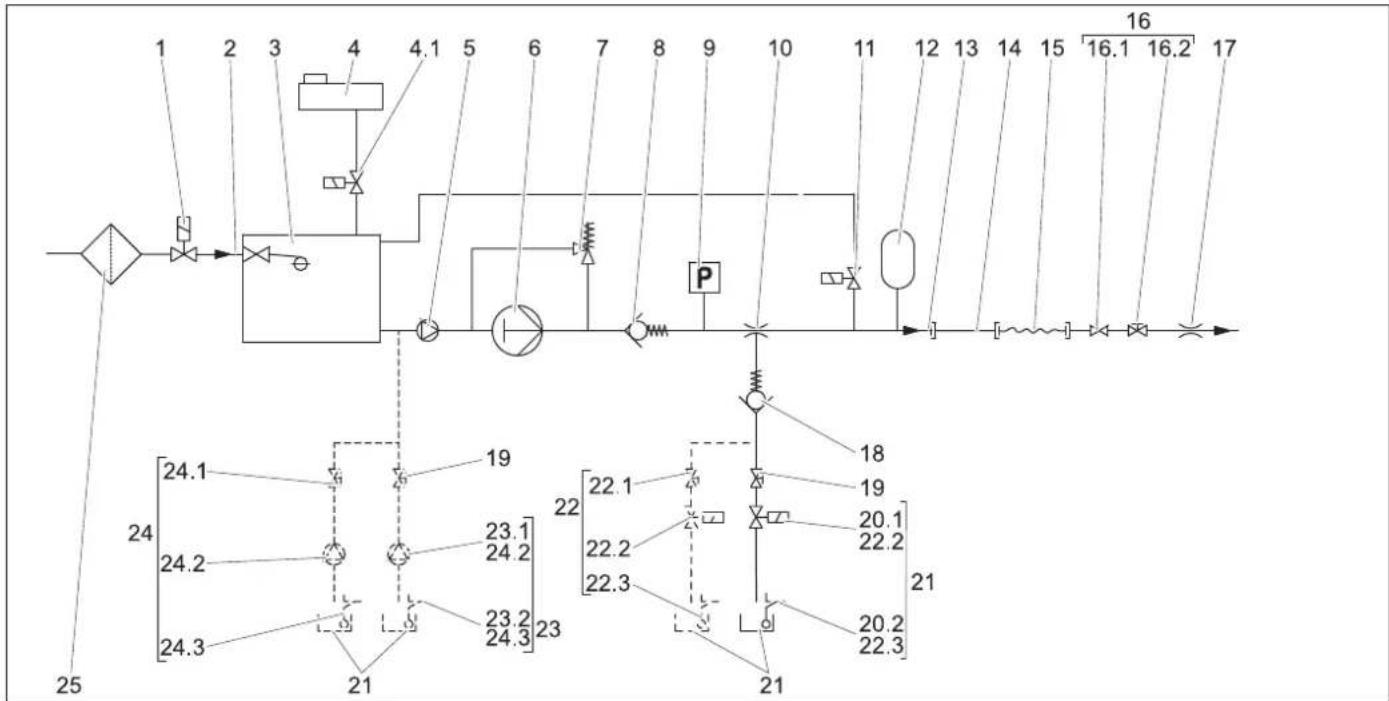
flowchart
graph TD
    A["1"] --> B["2"]
    B --> C["3"]
    C --> D["4"]
    D --> E["4.1"]
    E --> F["5"]
    F --> G["6"]
    G --> H["7"]
    H --> I["8"]
    I --> J["9"]
    J --> K["10"]
    K --> L["11"]
    L --> M["12"]
    M --> N["13"]
    N --> O["14"]
    O --> P["15"]
    P --> Q["16.1"]
    Q --> R["16.2"]
    R --> S["17"]
    T["24.1"] --> U["24.2"]
    U --> V["24.3"]
    V --> W["21"]
    X["23.1"] --> Y["24.2"]
    Z["23.2"] --> AA["24.3"]
    AB["22.1"] --> AC["22.2"]
    AD["22.3"] --> AE["22.2"]
    AF["20.1"] --> AG["20.2"]
    AH["20.2"] --> AI["22.3"]
    AJ["18"] --> AK[" "]
    AL["19"] --> AM[" "]
    AN["21"] --> AO[" "]
    AP["25"] --> AQ[" "]
1 Solenoid valve water supply (upgrade kit, optional)
2 Water inlet
3 Swimmer valve
4 Container of softener liquid with solenoid valve (4.1), only with model ST-H (option with model ST)
5 Prepressure pump, only with model ST-H
6 High pressure pump
7 Overflow valve
8 Back up valve
9 Pressure switch
10 Detergent injector
11 Pressure relief valve (upgrade kit, option)
12 Vibration dampener
13 High-pressure outlet
14 Pipe system (option)
15 High pressure hose
16 Trigger gun
with shutoff valve (16.1) and pressure/
volume regulation (16.2)
17 High pressure nozzle (triple nozzle)
18 Backflow valve, detergent suction under low pressure
19 Dosage valve for detergent
20 Level sensor detergent (upgrade kit, optional)
consisting of 1 detergent solenoid valve (20.1) and 1 detergent level sensor (20.2).
21 Cleaning agent container
22 Detergent dosing 2nd detergent, (upgrade kit, option), consisting of 1 detergent dispensing valve (22.1), 1 detergent solenoid valve (22.2), 1 detergent level sensor (22.3)
23 Detergent dosing 2nd detergent under high pressure (upgrade kit, option), consisting of 1 detergent pump (23.1), and 1 detergent level sensor (23.2)
24 Detergent dosing, double under high pressure (upgrade kit, option), consisting of 1 detergent dispensing valve (24.1), 2 detergent pumps (24.2), and 2 detergent level sensor (24.3)
25 Water filter (option)
Full pump capacity
With the decrease in total water flow the water runs through the water inlet, the swimmer tank, advance pressure pump hot water and through the high-pressure pump to the high-pressure outlet.
Parts removal
If only a part of the water capacity fed from the pump is needed, the rest of the flow runs through the flow regulator back to the suction site of the high-pressure pump.
Detergent
Detergent is suctioned via the detergent injector and metered using the detergent dispensing valve.
In order to activate the suction, the multi-nozzle must be set to "CHEM" (low pressure flat jet).
With the upgrade kit "Detergent dosing in high pressure mode (option)", detergent can be added via a detergent pump.
Automatic pump start
If the system pressure sinks during the standby period due to the opening of one of the consumers, the pressure switch will switch on the high pressure pump.
Softener system
Adding liquid softener will prevent the build-up of lime when operating with hot water. Starting with a hardness range of "medium" (8.4 - 14 °dH) and a supply temperature of more than 6C, the upgrade kit for water softening (DGT) must be installed, or an external water softening system must be present. ST-H appliances are suitable for hot water operation of up to 85°C; ST appliances are suitable for supply water temperatures of up to 70°C.
Device elements
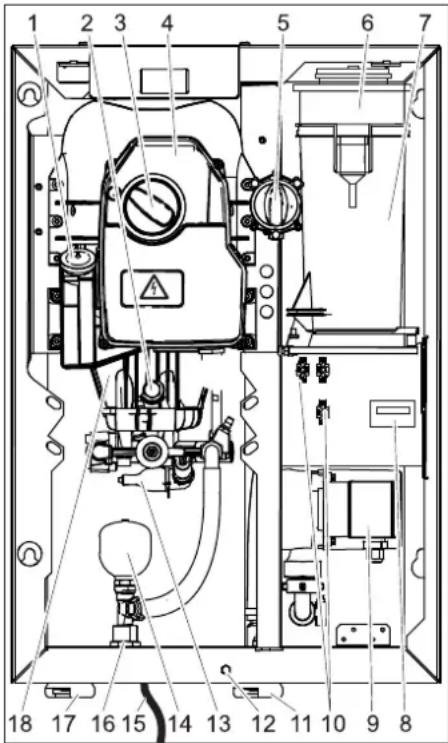
Appliance cover removed.
text_image
Technical diagram of an electrical enclosure with numbered components and safety warning labels1 Oil tank
2 Oil drain screw
3 Power switch
4 Electronics system
5 Dosage valve for detergent
6 Container of softener liquid (option)
7 Float tank
8 Hourmeter (option)
9 Prepressure pump (model ST-H only)
10 Connectors for upgrade kits
11 Water input (HD 7/16, HD 8/19)
12 Fastening screw for device hood
13 Pressure switch
14 Vibration dampener
15 Mains cable with mains plug (not with all appliance versions)
16 High-pressure connection EASY!Lock
17 Water inlet (HD 13/12)
18 High-pressure pump
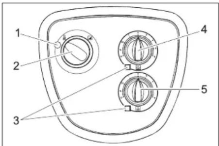
Operating elements
text_image
1 2 3 4 51 Indicator lamp
Glows green: Appliance ready to operate.
Blinks green: Readiness period elapsed or maximum time for continuous operation exceeded (hose break fuse).
Glows yellow: Fill in softener liquid (option).
Blinks yellow: Lack of water (option)
Glows red: Leaks in the high pressure system.
2 Power switch
3 Indicator lamp for detergent
Glows if detergent container is empty
(option).
4 Dosage valve I for detergent
5 Dosage valve II for detergent (optional)
text_image
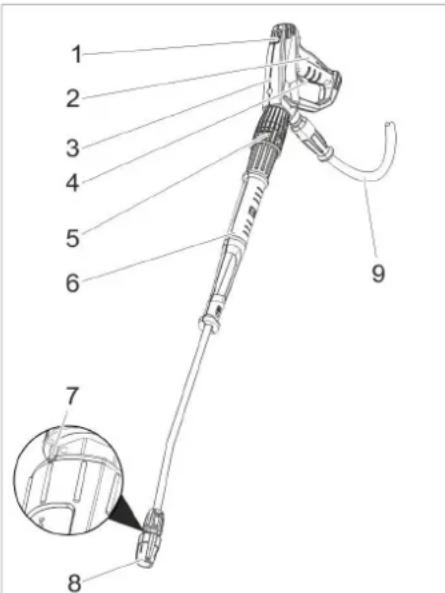
Technical diagram of a handheld device with numbered parts, highlighting internal components and an inset detail view.1 Safety catch
2 Trigger
3 Trigger gun EASY!Force
4 Safety lever
5 Pressure/quantity regulation (option)
6 Spray lance EASY!Lock
7 Marking of the triple nozzle
8 Triple nozzle EASY!Lock
9 High pressure hose EASY!Lock
Operation
Safety instructions
The operator must use the appliance correctly. When working with the appliance, he must consider the local conditions and pay due care and attention to other persons, in particular children, who are nearby. Never leave the appliance unattended when it is in operation.
△DANGER
- Only operate the equipment with the front cover closed.
- Risk of injury! Device, tubes, high pressure hose and connections must be in faultless condition. If they are not in a perfect state then the appliance must not be used.
△DANGER
- The jet must not be directed at other persons or directed by the user at him/herself to clean clothing or footwear.
- Risk of injury from parts flying off! Flying-off fragments or objects can injure people or animals. Never direct the water jet on fragile or loose objects.
△DANGER
Long hours of using the appliance can cause circulation problems in the hands on account of vibrations.
It is not possible to specify a generally valid operation time, since this depends on several factors:
– Proneness to blood circulation deficiencies (cold, numb fingers).
– Low ambient temperature. Wear warm gloves to protect hands.
– A firm grip impedes blood circulation.
- Continuous operation is worse than an operation interrupted by pauses.
In case of regular, long-term operation of the device and in case of repeated occurrence of the symptoms (e.g. cold, numb fingers) please consult a physician.
Making the plant ready for operations
DANGER
Risk of injury on account of the emanating water jet that could be hot!
→ Check high pressure hose, pipe connections, fittings and water jet for damage every time before use.
→ Replace leaky components immediately and seal all leaky connection points immediately.
→ Check hose coupling to ensure that it sits firmly and is leak-proof.
ATTENTION
Risk of damage on account of dry running.
→ Check filling level of the detergent tank and refill if required.
→ Check softener fluid level and refill if necessary.
Opening/closing the trigger gun
→ To open the trigger gun: Actuate the safety lever and trigger.
→ To close the hand spray gun: Release the safety lever and trigger.
High pressure operation
Note:
The appliance is equipped with a pressure switch. The motor starts up only when the lever of the pistol is pulled
→ Open the water supply.
→ Plug in the mains plug.
(Only with appliance versions with power cable and mains plug).
→ Set the appliance switch to "I". The indicator lamp glows green.
→ Release the trigger gun. To do so, push the safety catch towards the back.
→ Open the hand spray gun.
△DANGER
When adjusting the pressure/quantity regulation, make sure that the screw connection of the spray lance does not become loose.
→ Set working pressure and water quantity by turning (rungless) at the pressure and quantity regulation (option) (+/-).
Select spray type
→ Close the hand spray gun.
→ Turn the casing of the nozzle till the desired symbol matches the marking.
| High pressure circular spray (0°) for specially stubborn dirt | |
| Flat low pressure spray (CHEM) for operating using detergents or cleaning at low pressure. | |
| High pressure flat spray (25°) for large dirt areas |
Operation with detergent
△CAUTION
Unsuitable detergents can cause damage to the appliance and to the object to be cleaned. Use only those detergents that have been approved by Kärcher. Observe the dosage and other instructions provided with these detergents. For considerate treatment of the environment use detergent economically.
Follow the safety instructions for using detergents.
Kärcher detergents ensure smooth functioning. Please consult us or ask for our catalogue or our detergent information sheets.
→ Place the detergent can under the device.
→ Hang in the detergent hose into the detergent can.
→ Set nozzle to "CHEM".
→ Set dosing value for detergent to the desired concentration.
Recommended cleaning method
→ Spray the detergent sparingly on the dry surface and allow it to react, but not to dry.
→ Spray off loosened dirt with the high-pressure ray.
→ After operations, dip the filter in clear water. Turn the dosing valve to the highest detergent concentration. Start the appliance and rinse for one minute.
Interrupting operation
→ Close the hand spray gun.
The appliance switches off.
→ Secure the trigger gun. To do so, push the safety catch towards the front.
After the interruption:
→ Release the trigger gun. To do so, push the safety catch towards the back.
→ Open the hand spray gun. The appliance will switch on again.
Operational readiness period
The operational readiness period starts when the trigger gun is closed. The device can no longer be started by opening the trigger gun if this operational readiness period (5 to 120 minutes) expires.
The indicator lamp blinks green.
→ To restart, turn the device switch briefly to "0" and then again to "I".
Note:
Customer service can set the operational readiness period.
Restart the operation readiness time
→ Set the appliance switch to "0".
→ Wait for a while.
→ Set the appliance switch to "I".
or
→ Use the respective button on the remote control (option).
Turn off the appliance
→ Shut off water supply.
→ Open the hand spray gun.
→ Switch on the pump with the power switch and allow to run for about 5-10 seconds.
→ Close the hand spray gun.
→ Set the appliance switch to "0/OFF".
→ Pull main plug out of socket with dry hands only.
(Only with appliance versions with power cable and mains plug).
→ Remove water connection.
→ Activate hand spray gun until device is pressure less.
→ Secure the trigger gun. To do so, push the safety catch towards the front.
Frost protection
ATTENTION
Frost will destroy the not completely water drained device.
The machine should be stored in frost-free rooms. In case there is frosting risk, for e.g. if the machine is installed in open areas, then the machine must first be emptied and flushed using an anti-freezing agent.
Emptying the appliance
→ Remove the water inlet hose on the appliance.
→ Unscrew the high pressure hose from the appliance.
→ Let the appliance run till the pump and pipes are empty (max. 1 minute).
In case of longer operational breaks:
→ Fill in normal anti-frost agents in the swimmer tank right until the top.
→ Place the collection trough under the high pressure exit.
→ Turn on the equipment and let it run until the equipment is completely rinsed.
Switch-off in case of emergency
→ Turn the emergency-stop switch to "0".
→ Shut off water supply.
→ Activate trigger gun until device is pressure-less.
Remove the appliance cover
→ Unscrew the fastening screw of the appliance cover.
→ Slightly lift up the appliance cover and remove it toward the front.
Transport
△CAUTION
Risk of injury and damage! Observe the weight of the appliance when you transport it.
ATTENTION
Protect the trigger from damage during transport.
→ When transporting in vehicles, secure the appliance according to the guidelines from slipping and tipping over.
Storing the device
△CAUTION
Risk of injury and damage! Note the weight of the appliance in case of storage.
Care and maintenance
△DANGER
Risk of injury! Switch off the power switch with all maintenance and repair work. Pull the mains plug and secure it against being plugged in again
△DANGER
Risk of injury on account of the emanating water jet that could be hot! During all tasks:
– Close locking tap of fresh water.
- Let the hot parts of the plant cool down.
- Depressurise the plant by opening all hand-spray guns.
The bases of a safe operating of the equipment is thr regularly maintenance according to the following maintenance plan.
Use exclusively original parts of the manufacturer or those parts recommended by him like
– replacement and wear parts
- Accessory parts
- F u e l
- Detergent
Safety inspection/ maintenance contract
You can sign with your dealer a contract for regular safety inspection or even sign a maintenance contract. Please take advice on this matter.
Maintenance schedule
| Time Activity As | sembly affected | Performance of whom | ||
| daily Check hand-spray gun | Hand spray gun Check whether | the hand-spray gun closes tightly without any leaks. Check the protection mechanism against accidental switching. Replace defective hand-spray guns. | Operator | |
| opinion Power cord(Only with appliance versions with power cable and mains plug). | Check the mains cable regularly for damage such as aging or formation of cracks. If you find a damage, then the cable must be replaced before using it any further. | Operator/Customer Service | ||
| Test fill level Detergent tank, Installation water softener (optional) | Check filling level, refill if necessary. Operator | |||
| Check high pressure hoses | Outlets, hoses towards working machine | Check hoses to see if there are damages. Replace defect hoses immediately. Danger of accident! | ||
| weekly or after 40 operating hours | Check the unit for leaks | Entire plant Check pumps and pipes for leaks. Inform Customer Service if there is oil loss or if there is a leakage of more than 10 drops of water per minute. | Operator/Customer Service | |
| Check oil level | Oil tank at the pump | If the oil is milky, it needs to be replaced. It is recommended likewise in this case that the pump's oil seal be changed (Customer Service). | Operator/Customer Service | |
| Check oil level | Oil tank at the pump | Check oil level of the pump. Refill oil if required (Order no. 6.288-016) | Operator | |
| Clean filter | Filter at the detergent suck hose | Clean filter at the detergent suck hose. | Operator | |
| Test vibration dampener | Vibration dampener | If the vibration of the pump increases it indicates that the pressure tank is defective. Replace the vibration dampener. | Customer Service | |
| monthly or after 200 operating hours | Cleaning the sieve | Sieve in water inlet | Check, dismantle sieve and clean it. | Operator |
| Test swimmer valve | Float tank | When the swimmer valve is closed no water can escape the overflow. | Operator | |
| Test automatic start | Pressure switch Pump is at a standstill, because no water removal has taken place. Turn on the hand spray gun. If the pressure in the high pressure network falls below 3 MPa, the pump must be turned on. | Operator | ||
| Tighten hose clips | All hose clips | Tighten the hose clips using a torque wrench. Tightening torque up to a diameter of 28 mm = 2Nm, from 29 mm = 6 Nm. | Operator | |
| annually or after 1000 operating hours | Oil change | High-pressure pump | Drain off oil. Refill oil. Check oil level in the oil tank. | Operator |
| Check unit for calcium deposits. | entire water system | Improper functioning of valves or pumps can be an indication of calcium deposits. If necessary decalcify | Operator trained in de-calcification | |
| annual | Safety check | Entire plant | Safety check according to the guidelines for fluid spraying equipment. | Technical expert |
Maintenance contract
In order to guarantee a reliable operation of the equipment, we success, you signed a maintenance agreement. Please refer to your local Kärcher service department.
Maintenance Works
Who may perform maintenance?
Operator
Work designated with the sign "Operator" may only be carried out by persons who have been instructed in the safe operation and maintenance on the high pressure plant.
Electricians
Only persons with a professional training in the electro-technical area.
■ Customer Service
Work designated with the sign "Customer Service" may only be done by the fitters of Kärcher Customer Service.
Oil change
⚠ WARNING
Risk of burns due to hot oil or hot parts of the plant. Allow the pump to cool down for minutes before oil change.
Note:
Used oil must only be disposed of by the designated collection points. Please turn in used oil there. Polluting the environment with used oil is prosecutable.
For oil type refer to technical specifications.
text_image
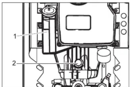
Technical diagram of a mechanical assembly with numbered components and labeled parts1 Oil tank
2 Oil drain screw
→ Place the collection trough under the oil drain screw.
→ Remove the lid of the oil container.
→ Unscrew the oil drain screw and collect oil.
→ Fix in the oil drain screw and tighten it.
→ Slowly fill in new oil until the "MAX" marking on the oil container.
→ Attach the lid of the oil container.
→ Dispose of old oil ecologically or turn it in at a collection point.
Descaling
Calcium deposits can lead to:
– higher pipe resistances
– even to failure of the components with heavy calcium deposits
DANGER
– Risk of explosion due to combustible gases! Smoking strictly prohibited during decalcification. Ensure proper ventilation.
– Risk of chemical burns on account of acid! Wear protective glasses and protective gloves.
Note:
– Follow the specifications of the accident prevention regulation BGV A1.
– Follow instructions for use on the lable of the decalcifying agent.
According to statutory requirements, only tested and approved boiler decrusting agents may be used.
- RM 100 (Order No. 6.287-008) dissolves chalk and simple compounds of chalk and detergents residues.
- RM 101 (Order No. 6.287-013) dissolves the deposits that cannot be dissolved using RM 100.
Note:
As an anti-corrosion measure and for neutralising the acid residue, we recommend that you finally pump an alkaline solution through the machine (for e.g. RM 81) via the detergent tank.
■ First decalcify the swimmer tank.
→ Shut off water supply.
→ Remove the lid of the swimming tank.
→ Remove the hose from the suction site of the pump for the swimming tank on the pump site.
→ Seal the free end of the hose.
→ Fill in 7 percent decalcification solution.
→ Remove resin completely from the tank after decalcification.
■ Decalcify the high pressure installation:
→ Remove the high pressure hose from the network supply and hang it in the swimmer tank.
→ Run the calcium dissolving acid mixture prepared in the tank through the installation's cycle, allow it to take effect, rinse.
Troubleshooting
△DANGER
Risk of electric shock.
Risk of injury! Switch off the power switch with all maintenance and repair work.
Pull the mains plug and secure it against being plugged in again
△DANGER
Risk of injury on account of the emanating water jet that could be hot!
△DANGER
Risk of accident while working on the unit! During all tasks:
- Close locking tap of fresh water.
- Let the hot parts of the plant cool down.
– Depressurise the plant by opening all hand-spray guns.
Who may remedy faults?
Operator
Work designated with the sign "Operator" may only be carried out by persons
who have been instructed in the safe operation and maintenance on the high pressure plant.
Electricians
Only persons with a professional training in the electro-technical area.
■ Customer Service
Work designated with the sign "Customer Service" may only be done by the fitters of Kärcher Customer Service.
| Fault Possible cause Remedy of whom | |||
| Water stream is uneven. Nozzle is blocked. Clean the nozzle. Operator | |||
| Inadequate or no flow of detergent | Dosage adjusted too low. Increase dose. | Operator | |
| Nozzle is set to "High pressure". | Set nozzle to "CHEM". | Operator | |
| Suction filter in the detergent tank is dirty. | Clean the suction filter. | Operator | |
| Detergent suck hose leaking. | Replace suck hose. | Customer Service | |
| Manual detergent dispensing valve occluded, defective. | Check; clean, replace, if required. | Customer Service | |
| Pressure does not build up in the pump | Nozzle is set to "CHEM" | Set nozzle to "High pressure". | Operator |
| Air in the high pressure pump | Ventilate the appliance (see "System start-up") | Operator | |
| Suction site pipe leaking. | Check screw fittings and hoses. | Operator | |
| Not enough water | Ensure adequate water supply. | Operator | |
| Sieve in the water inlet is dirty | Clean sieve. | Operator | |
| High pressure hose leaking. | Replace high pressure hose. | Customer Service | |
| Piping leaking. | Repair piping system. | Customer Service | |
| Flow regulator defective. | Test flow regulator, repair. | Customer Service | |
| The valve in the pump is defective. | Replace valve. | Customer Service | |
| High pressure pump is knocking; manometer (option) is swaying wildly | Vibration dampener is defective. | Replace vibration dampener. | Operator |
| Water pump does not suck in adequate air. | Check suction system and remove leaks. | Operator | |
| Detergent container is empty | Refill detergent tank. | Operator | |
| Water flow temperature too hot. | Lower water temperature. | Operator | |
| Water flow blocked. | Clean sieve in the water inlet, check the water flow. | Operator | |
| Valve plate or valve spring is defective. | Replace parts | Customer Service | |
| Advance pump calcified or defective. | Check advance pump. Operator | ||
| The installation does not start when switched on or when pressing the remote control (optional). | Appliance switch is switched off | Turn it on. | Operator |
| On-board electricity supply interrupted. | Turn it on. | Operator | |
| Pressure switch is defective | Replace pressure switch. | Customer Service | |
| Motor protection switch was triggered by overflow or loss of a phase of the electricity supply. | Check the voltage of the three phases. | Electrician/ Customer Service | |
| Motor protection switch is set incorrectly. | Adjust according to circuit diagram. | Electrician/ Customer Service | |
| Motor protection switch for controls and advance pressure pump triggered. | Check motor protection switch. | Electrician/ Customer Service | |
| Control safety transformer defective. | Examine the cause, replace the control safety device. | Electrician/ Customer Service | |
| Circuit board defective. | Check circuit board, replace if required. | Customer Service | |
| Pump starts during the stand-by period and not when the hand spray gun is opened. | Pressure switch or pressure switch cable defective. | Replace the pressure switch or cable. | Customer Service |
| Installation does not switch off. | Pump is drawing in air over the empty detergent tank. | Refill the detergent tank, ventilate suction line. | Operator |
| Pressure switch is defective. | Replace pressure switch. | Electrician/ Customer Service | |
Technical specifications
| HD 7/16-4 STHD 7/16-4 ST-H | HD 9/18-4 STHD 9/18-4 ST-H | HD 13/12-4 STHD 13/12-4 ST-H | |||||||||||
| Electrical connection | |||||||||||||
| Voltage V 400 230 440 220 400 230 | 440 220 400 | 230 440 220 | |||||||||||
| C u | r | r | e | ||||||||||
| F r e | q | u | e | n c | y | H | |||||||
| Connected load kW 5,0 6,8 7,3 | |||||||||||||
| E l e c t r i | c a | l | p | r | o | t e | c | t | i o | n | ( s l | ||
| Type of protection | IPX5 | ||||||||||||
| Power supply | mm2 | 2,5 | 4 | 2,5 | 4 | 2,5 | 4 | 2,5 | 4 | 2,5 | 4 | 2,5 | 4 |
| Water connection | |||||||||||||
| Min. feed volume | l/h (l/min) | 800 (13,3) | 1000 (16,7) | 1400 (23,3) | |||||||||
| Max. feed pressure | MPa (bar) | 1,0 (10) | |||||||||||
| Feed temperature (max.), ST | °C | 70 | |||||||||||
| Feed temperature (max.), ST-H | °C | 85 | |||||||||||
| Performance data | |||||||||||||
| Operating pressure of water (using standard nozzle) | MPa (bar) | 3...16 (30...160) | 4...18 (40...180) | 3...12 (30...120) | |||||||||
| Size of standard nozzle | 043 | 040 | 055 | 098 | |||||||||
| Max. operating over-pressure | MPa (bar) | 19 (190) | 20 (200) | 15 (150) | |||||||||
| Flow rate | l/h (l/min) | 300...700 (5...11,7) | 460...900 (7,7..15) | 650...1300 (10,8...21,7) | |||||||||
| Detergent suck in | l/h (l/min) | 0...42 (0...0,7) | 0...54 (0...0,9) | 0...78 (0...1,3) | |||||||||
| % | 0...6 | ||||||||||||
| Recoil force of hand spray gun (max.) | N | 35 | 47 | 56 | |||||||||
| Values determined as per EN 60335-2-79 | |||||||||||||
| Hand-arm vibration value | |||||||||||||
| Hand spray gun | m/s2 | 1,7 3,0 2,1 | |||||||||||
| Spray lance | m/s2 | 3,0 4,2 2,8 | |||||||||||
| Uncertainty K | m/s2 | 0,3 0,3 0,3 | |||||||||||
| Sound pressure level LpA | dB(A) | 70 | 71 | 74 | |||||||||
| Uncertainty KpA | dB(A) | 3 | 3 | 3 | |||||||||
| Guaranteed sound power level | dB(A) | 87 | 88 | 91 | |||||||||
| Fuel | |||||||||||||
| Amount of oil | l | 0,5 | 0,75 | 1,25 | |||||||||
| Oil grade | -- | SAE 90 Hypoid | |||||||||||
| Dimensions and weights | |||||||||||||
| Width | mm | 533 | |||||||||||
| Height | mm | 790 | |||||||||||
| Depth | mm | 420 | |||||||||||
| Weight, basic appliance, ST | kg | 58 | 65 | 78 | |||||||||
| Weight, basic appliance, ST-H | kg | 62 | 69 | 82 | |||||||||
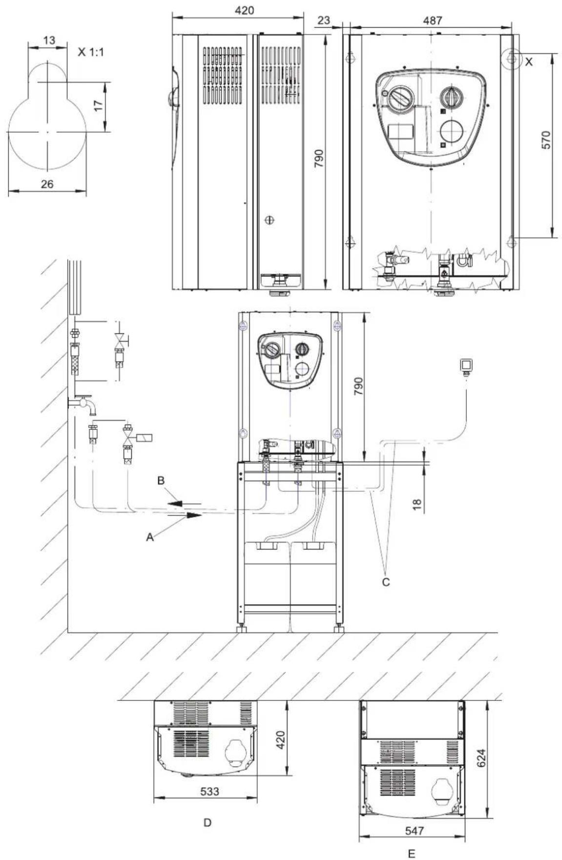
A Water inlet 3/4"
B High-pressure connection EASY!Lock
C Electrical connection from the bottom
D Wall mount
E On r a c k
Accessories
Detergent
Detergents simplify the cleaning tasks. The table gives a selection of detergents. Please read the instructions on the packaging carefully before working with any detergents.
■ The following types of detergent are not suitable because they damage the equipment.
- cleaning agent containing nitrit acid - cleaning agent containing active chlorinate
| Area of application | Target group Detergent Ka | rcher descrip- | tion | Dosage |
| Foaming Food industry/disassembly facilities | Disinfection cleaning RM 732 1-3% | |||
| Disinfectant RM 735 0,75-7% | ||||
| Foam disinfecting detergent, alkali-based | RM 734 2-5% | |||
| Beverage facilities/wine cel-lars | Foam detergent, alkali-base RM 58 ASF 1-2% | |||
| Foam cleaner, acidic RM 59 ASF 1-2% | ||||
| Foam disinfecting detergent, alkali-based | RM 734 2-5% | |||
| Community | Exterior foam cleaner, neutral | RM 57 | ||
| Disinfecting cleaner, inside | RM 732 1-3% | |||
| Agriculture | Disinfection cleaning RM 732 1-3% | |||
| Disinfectant RM 735 0,75-7% | ||||
| High-pressure cleaning | Beverage facilities/wine cel-lars | Universal cleaner | RM 55 | 0,5-8% |
| Foam disinfecting detergent, alkali-based | RM 734 2-5% | |||
| Community | Active cleanser, alkali-based RM 81 | 1-5% | ||
| Agriculture | Active cleanser, alkali-based RM 31 | 1-5% | ||
| Active cleanser, alkali-based RM 81 | 1-5% | |||
| Ship equipment | Active cleanser, alkali-based RM 81 | 1-5% | ||
| Automotive/lorry workshop A | Active cleaner, alkali-based (engine/ parts) | RM 31 | 1-5% | |
| Active cleaner, alkali-based (vehicle, top and bottom wash) | RM 81 | 1-5% | ||
| Floor cleaning | Food industry/disassembly facilities | Intensive basic cleaner | RM 750 1-5% | |
| Floor basic cleaner | RM 69 | 0,5-1% | ||
| Beverage facilities/wine cel-lars, community | Intensive basic cleaner | RM 750 1-5% | ||
| Floor basic cleaner | RM 69 | 0,5-1% | ||
| Automotive/lorry workshop I | Intensive basic cleaner | RM 750 1-5% | ||
| Floor basic cleaner | RM 69 | 0,5-1% | ||
| Ship equipment | Intensive basic cleaner | RM 750 1-5% | ||
| Floor basic cleaner | RM 69 | 0,5-1% | ||
| Washing brush | Community | Exterior active cleanser, alkali-based | RM 81 | 1-5% |
| Universal cleaner | RM 55 | 0,5-8% | ||
| Automotive/lorry workshop A | Active cleaner, alkali-based (vehicle, top and bottom wash) | RM 81 | 1-5% | |
| Ship equipment | Exterior active cleanser, alkali-based | RM 81 | 1-5% | |
* = only for short use, two-step method, rinse with clean water
** = ASF = easy-to-dispose
*** = Foam-Star 2000 is best suited for initial spraying
Attachment sets
| Remote controls | |||
| 1 Upgrade kit, remote re-lease* | 2.637-491.0 | 1 operating point. Restoring the operation readiness after the readiness period has elapsed. Several operating stations can be used parallelly. | |
| 2 Upgrade kit for remote con-trol, HD simple* | 2.744-014.0 | 1 operating point. Actuation of the high pressure pump and up to two detergent. Use of 2 operating stations or one operating station and one coin remote control (item 3) in connection with the priority switch (item 4). | |
| 3 Upgrade kit coin remote control* | 2.642-422.0 Co | n remote control. Actuation of the high pressure pump and up to two detergents after coin insertion. | |
| 4 | Upgrade kit priority switch* | 2.638-200.0 | Switching between 2 remote controls (item 2) or one remote control (item 2) and one coin remote control (item 3). |
| 5 Upgrade kit control electronics, multi remote control* | 2.744-036.0 | Actuation of the high pressure pump and two detergents from up to 6 operating sta-tions (item 6). Additional connectivity for a coin remote control (item 3). | |
| 6 Upgrade kit operating sta-tion, multi remote control | 2.744-015.0 O | erating station for multi remote control (item 5). | |
| 7 Upgrade kit emergency stop* | 2.744-002.0 Int | interrupts the mains supply to the system. | |
| 8 | Upgrade kit junction box | 2.744-798.0 | Is needed to connect the upgrade kits (item 1) through (item 7) to the appliance. Com-pletely wired, connection via connectors on the appliance. |
| 9 Upgrade kit, connection box for remote release | 2.209-807.0 | Required to connect the upgrade kits remote release (item 1) and emergency stop (item 7). | |
| Attachment kits | |||
| 1 | Upgrade kit pressure relief | 2.209-773.0 | Relieves the high pressure system of pressure after the readiness period has elapsed. |
| 2 Upgrade kit, single deter-gent for low-pressure opera-tion* | 2.209-779.0 | Necessary when selecting one detergent via the remote control. Consists of 1 sole-noid valve and 1 level sensor**. | |
| 3 Upgrade kit, double deter-gent for low-pressure opera-tion* | 2.209-780.0 | Necessary when selecting a second detergent via the remote control (optional for item 5). Consists of 1 solenoid valve, 1 level sensor and 1 dispensing valve. | |
| 4 Upgrade kit, single deter-gent in high pressure mode* | 2.209-799.0 | Allows the dispensing of detergent in high pressure mode. Is necessary to actuate a detergent via a remote control. The appliance has standard detergent dispensing in low pressure mode, which is activated by switching the triple nozzle. When installing this upgrade kit, you will not need to switch over with the triple nozzle. | |
| 5 Upgrade kit, double deter-gent in high pressure mode* | 2.209-800.0 | Allows the dispensing of detergent in high pressure mode. Is necessary to actuate a second detergent via a remote control. The appliance has standard detergent dis-pensing in low pressure mode, which is activated by switching the triple nozzle. When installing this upgrade kit, you will not need to switch over with the triple nozzle. | |
| 6 Upgrade kit for water softening (DGT) | 2.209-777.0 | Prevents lime buildup in hot water mode by dispensing softener liquid. | |
| 7 | Upgrade kit hour meter | 2.209-778.0 | Captures the operating times of the appliance to be able to keep the maintenance in-tervals. |
| 8 | HWE 860 | 3.070-036.0 | Heats the supplied water using an electrically heated boiler. |
| 9 | Upgrade kit floor rack St | 2.210-058.0 | To install the appliance when a wall mount is not possible. Steel model, painted. |
| 10 | Upgrade kit floor rack VA | 2.210-059.0 | To install the appliance when a wall mount is not possible. Stainless steel model, rustproof. |
| 11 Upgrade kit solenoid valve for water inlet | 2.209-788.0 Int | interrupts the water supply during appliance standstill. | |
| * upgrade kit junction box required | |||
| **The appliance has standard detergent dispensing in low pressure mode, which is activated by switching the triple nozzle. | |||
Installing the plant

Only for authorised technicians!
Unpacking
- Check the contents of the pack before unpacking.
– In case of transport damage inform vendor immediately. - Store the drilling template on the carton to assemble the device.
Installation
Note:
The water connection, the high pressure network as well as the electrical connection can only be carried out by authorised experts in accordance with local regulations.
- The installation should be set-up in a dry, non-explosive environment.
– The installation should be installed on firm and even ground. - The installation should be easily accessible for maintenance work.
The following are required for installation:
- Wall mount
- Installation with the mounting kit floor rack (optional)
Fasten the device to the wall
△CAUTION
Risk of personal injury or damage! Note the weight of the appliance during installation.
ATTENTION
Risk of damage! Freezing water in the appliance can destroy parts of the appliance. The machine should be stored in frost-free rooms. In case there is frosting risk, for e.g. if the machine is installed in open areas, then the machine must first be emptied and flushed using an anti-freezing agent.
→ Check the wall's support capacity.
→ Mark the wall using the drill template on the packaging.
→ Drill the bores into the wall.
→ Attach the installation materials to the wall.
→ Remove the appliance cover.
→ Hang up the appliance and secure it against falling down.
→ Replace the appliance hood and fasten it with screws.
Electrical connection
- For connection values, see technical data and type plate.
- The power supply designed for operating the plant must be suitable for continuous operations.
- The electrical connections must be done by an electrician according to IEC 60364-1.
- Current-carrying parts, cables and appliances in the working area must be installed in a defectless state and must be protected against water sprays.
Water supply
- Design the water supply for continuous operations.
- The water feed line is provided with a stop valve and can be moved over a pressure hose and attached to the high pressure system.
- If the cross section of the line is too small or if the advance pressure is too low, there will be a lack of water.
- When the advance pressure or the rinse pressure is too high, it is absolutely necessary to install a pressure reducer.
– A water drain must be present at installation site.
High pressure installation
For installation, please follow the specifications of the VDMA sheet 24416 "High pressure cleaners; fixed high pressure cleaning systems; concepts, requirements, installation, testing" (the German version can be procured from Beuth Verlag, Cologne, www.beuth.de).
- The fixed pipe network and the installation should be connected with a high pressure line.
- The fixed pipe network should be placed as straight as possible. High pressure piping systems should be installed correctly with removable and fixed clips, taking into consideration the variation in length caused by the effects of heat and pressure.
- In order to keep pressure losses in the high pressure piping as small as possible, we recommend the following: Pipelines: Nominal width DN 15 (1/2"). Hose lines: Nominal width DN 8.
In regards to the above mentioned standard values, the length of the pipes and the number of direction changes and fittings must be taken into account.
Install hand spray gun, spray lance and nozzle
Note: The EASY!Lock system joins components with a quick-fasten thread solidly and securely with just one turn.

text_image
Technical diagram showing two mechanical assembly steps with numbered components and directional arrows indicating assembly direction.Illustration, see "Operating components".
→ Mount the nozzle on the spray lance (marking on the adjustment ring at the top) and hand-tighten it (EASY!Lock).
→ Join the spray lance with the trigger gun and tighten until hand-tight (EASY!Lock).
→ Join the high-pressure hose with trigger gun and tighten until hand-tight (EASY!Lock).
→ Connect the high-pressure hose to the high-pressure outlet of the device or the high-pressure pipeline network (EASY!Lock).
Install the detergent tank
The detergent tank is set up in such a way, that the bottom of the tank is located not more than 1.5 m unter the unit.
Initial startup
→ Check that water inlet has the required flow and the permissible temperature.
→ Check oil level of the pump.
natural_image
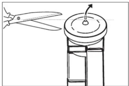
Line drawing of a sewing machine needle with scissors, showing blade and base structure (no text or symbols)→ Cut off tip of oil container.
Settings
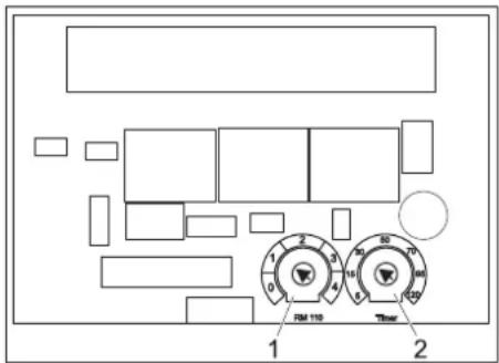
Adjustments are made on the control circuit board
The control circuit board is located in the electric box of the high pressure pump.
text_image
FM 110 Timer1 Potentiometer water hardness
2 Potentiometer readiness time period
Operational readiness period
→ Initiate the stand by-period with the potentiometer on the electronic control.
→ Adjustment by the manufacturer: 10 Minutes
The time can be set between 5 and 120 minutes. A simple scale of standard values is printed on the control board.
Installation water softener (optional)
Use hard water for hot water operation to protect against calcification In addition add water softener to the water. The dispensing flow can be adjusted to the degree of water hardness.
natural_image
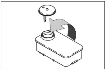
Diagram of a mechanical device with a knob and curved arrow indicating motion (no text or symbols)→ Fill the tank with Kaercher softener liquid RM 110 (Order no. 2.780-001).
→ Determining the hardness of tap water:
– through the public water supply works,
– using a hardness tester (order no.
6.768-004)
△DANGER
Dangerous electrical voltage! Setting may only be done by an electrician.
→ Start the rotation potentiometer on the water softener board. The scale displays the hardening ranges 1 to 4.
Deaerating the appliance
→ Unscrew the nozzle.
→ Switch on the appliance and let it run until the water exiting is bubble-free.
→ At the end let the appliance run for approx. 10 seconds - then switch off. Repeat the procedure for a couple of times.
→ Switch off the appliance and fit the nozzle again.
EU Declaration of Conformity
We hereby declare that the machine described below complies with the relevant basic safety and health requirements of the EU Directives, both in its basic design and construction as well as in the version put into circulation by us. This declaration shall cease to be valid if the machine is modified without our prior approval.
Product: High pressure cleaner
Type: 1.524-xxx
Relevant EU Directives
2006/42/EC (+2009/127/EC)
2014/30/EU
Applied harmonized standards
EN 55014-1: 2006+A1: 2009+A2: 2011
EN 55014-2: 2015
EN 60335-1
EN 60335-2-79
EN 61000-3-2: 2006+A1: 2009+A2: 2009
EN 61000-3-3: 2013
EN 62233: 2008
The undersigned act on behalf and under the power of attorney of the company management.
Authorised Documentation Representative S. Reiser
71364 Winnenden (Germany)
Phone: +49 7195 14-0
Fax: +49 7195 14-2212
Winnenden, 2016/11/01
Accessories and Spare Parts
Only use original accessories and spare parts, they ensure the safe and trouble-free operation of the device.
For information about accessories and spare parts, please visit www.kaercher.com.
Warranty
The warranty terms published by our competent sales company are applicable in each country. We will repair potential failures of the appliance within the warranty period free of charge, provided that such failure is caused by faulty material or defects in fabrication.
The warranty comes only into effect if your vender fills out the supplied reply card completely at purchase, stamps and signs and you send it to the local distribution company of your country.
In the event of a warranty claim please contact your dealer or the nearest authorized Customer Service centre. Please submit the appliance, including all accessories, and the proof of purchase.
Customer Service
| Plant type: Manufact. no.: Start-up on: | ||
Testing done on:
Findings:
Signature
Testing done on:
Findings:
Signature
Testing done on:
Findings:
Signature
Testing done on:
Findings:
Signature

www.kaercher.com/REACH
text_image
Technical diagram of an electrical enclosure with numbered components and safety warning labelstext_image
Technical diagram of a mechanical assembly with numbered components and labeled partstext_image
Technical diagram showing two mechanical assembly steps with numbered components and directional arrows indicating assembly direction.natural_image
Line drawing of a sewing machine needle being cut with scissors, showing blade and base structure (no text or symbols)natural_image
Diagram of a device with a knob and arrow indicating motion or force (no text or symbols)2006/42/CE (+2009/127/CE)
2014/30/UE
71364 Winnenden (Germany)
Winnenden, 2016/11/01
www.kaercher.com/REACH
Norme di sicurezza
text_image
Technical diagram of an electrical enclosure with numbered components and safety warning labelstext_image
Technical diagram of a mechanical assembly with numbered components labeled 1 and 2text_image
Technical diagram showing two mechanical assembly steps with numbered components and directional arrows indicating assembly direction.natural_image
Line drawing of a sewing machine with scissors and base mount (no text or symbols)text_image
FM 110 Thernatural_image
Diagram of a mechanical device with a knob and curved arrow indicating motion (no text or symbols)2006/42/CE (+2009/127/CE)
2014/30/UE
71364 Winnenden (Germany)
Tel.: +49 7195 14-0
Fax: +49 7195 14-2212
Winnenden, 2016/11/01
Accessori e ricambi
www.kaercher.com/REACH
text_image
Technical diagram of an electrical enclosure with numbered components and safety warning labelstext_image
Technical diagram of a mechanical assembly with numbered components and labeled parts1 Oliereservoir
2 Olie-aftapschroef
text_image
Technical diagram showing two mechanical assembly steps labeled 1 and 2, with numbered components and directional arrows.natural_image
Line drawing of a sewing machine with scissors and base mount (no text or symbols)natural_image
Diagram of a mechanical device with a knob and curved arrow indicating motion (no text or symbols)71364 Winnenden (Germany)
Tel.: +49 7195 14-0
Fax: +49 7195 14-2212
Winnenden, 2016/11/01
www.kaercher.com/REACH
text_image
Technical diagram of an electrical enclosure with numbered components and safety warning labelstext_image
Technical diagram of a mechanical assembly with numbered components and labeled parts1 Recipiente de aceite
2 Tornillo purgador de aceite
natural_image
Line drawing of a sewing machine with scissors and base mount (no text or symbols)natural_image
Diagram of a mechanical device with a knob and arrow indicating motion (no text or symbols)71364 Winnenden (Germany)
Tele.: +49 7195 14-0
Fax: +49 7195 14-2212
Winnenden, 2016/11/01
www.kaercher.com/REACH
Avisos de segurança
text_image
Technical diagram of an electrical enclosure with numbered components and safety warning labelstext_image
Technical diagram of a mechanical assembly with numbered components and labeled partstext_image
Technical diagram showing two mechanical assembly steps with numbered components and directional arrows indicating motion or movement.Figura ver "Elementos de comando".
natural_image
Line drawing of a sewing machine with scissors and base mount (no text or symbols)natural_image
Diagram of a mechanical device with a knob and arrow indicating motion (no text or symbols)2006/42/CE (+2009/127/CE)
2014/30/UE
71364 Winnenden (Germany)
Tel.: +49 7195 14-0
Fax: +49 7195 14-2212
Winnenden, 2016/11/01
www.kaercher.com/REACH
text_image
Technical diagram of an electrical enclosure with numbered components and safety warning labelstext_image
Technical diagram of a handheld device with numbered parts and an inset close-up view highlighting a component.text_image
Technical diagram of a mechanical assembly with numbered components and labeled partstext_image
Technical diagram showing two mechanical assembly steps with numbered components and directional arrows indicating assembly direction.Figur se "Betjeningselementer".
natural_image
Line drawing of a sewing machine with scissors and base mount (no text or symbols)natural_image
Diagram of a mechanical device with a knob and curved arrow indicating motion (no text or symbols)2006/42/EF (+2009/127/EF)
2014/30/EU
71364 Winnenden (Germany)
Tlf.: +49 7195 14-0
Fax: +49 7195 14-2212
Winnenden, 2016/11/01
www.kaercher.com/REACH
25 Vannfilter (tilleggsutstyr)
full pumpekapasitet
text_image
Technical diagram of an electrical enclosure with numbered components and safety warning labelstext_image
Technical diagram of a handheld device with numbered parts, highlighting internal components and an inset detail view.text_image
Technical diagram of a mechanical assembly with numbered components and labeled parts1 Oljebeholder
text_image
Technical diagram showing two mechanical assembly steps with numbered components and directional arrows indicating assembly direction.natural_image
Line drawing of a sewing machine needle being cut with scissors, showing blade and base structure (no text or symbols)natural_image
Diagram of a mechanical device with a knob and curved arrow indicating motion (no text or symbols)2006/42/EF (+2009/127/EF)
2014/30/EU
S. Reiser
Head of Approbation
71364 Winnenden (Germany)
Tlf: +49 7195 14-0
Winnenden, 2016/11/01
www.kaercher.com/REACH
text_image
Technical diagram of an electrical enclosure with numbered components and safety warning labelstext_image
Technical diagram of a handheld device with numbered parts labeled 1 through 9, including an inset close-up view.text_image
Technical diagram showing two mechanical assembly steps with numbered components and directional arrows indicating assembly direction.Bild se "Manöverelement".
natural_image
Line drawing of a sewing machine with scissors and base mount (no text or symbols)natural_image
Diagram of a device with a knob and arrow indicating motion or force (no text or symbols)71364 Winnenden (Germany)
Tel.: +49 7195 14-0
Fax: +49 7195 14-2212
Winnenden, 2016/11/01
www.kaercher.com/REACH
Turvaohjeet
text_image
Technical diagram of an electrical enclosure with numbered components and safety warning labelstext_image
Technical diagram of a mechanical assembly with numbered components and labeled parts1 Öljysäiliö
2 Öljynpoistoruuvi
natural_image
Line drawing of a sewing machine with scissors and base mount (no text or symbols)natural_image
Diagram of a mechanical device with a knob and curved arrow indicating motion (no text or symbols)71364 Winnenden (Germany)
Puh.: +49 7195 14-0
Winnenden, 2016/11/01


