HDS 8184 C - Pressure washer Kärcher - Free user manual and instructions
Find the device manual for free HDS 8184 C Kärcher in PDF.
Download the instructions for your Pressure washer in PDF format for free! Find your manual HDS 8184 C - Kärcher and take your electronic device back in hand. On this page are published all the documents necessary for the use of your device. HDS 8184 C by Kärcher.
USER MANUAL HDS 8184 C Kärcher
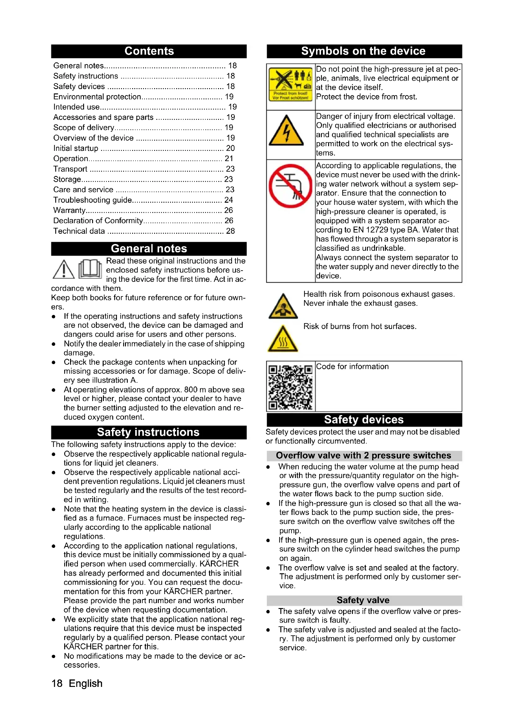
- 0,9 0,8 0,9 1 118 English Contents General notes Read these original instructions and the enclosed safety instructions before us- ing the device for the first time. Act in ac- cordance with them. Keep both books for future reference or for future own- ers. ● If the operating instructions and safety instructions are not observed, the device can be damaged and dangers could arise for users and other persons. ● Notify the dealer immediately in the case of shipping damage. ● Check the package contents when unpacking for missing accessories or for damage. Scope of deliv- ery see illustration A. ● At operating elevations of approx. 800 m above sea level or higher, please contact your dealer to have the burner setting adjusted to the elevation and re- duced oxygen content. Safety instructions The following safety instructions apply to the device: ● Observe the respectively applicable national regula- tions for liquid jet cleaners. ● Observe the respectively applicable national acci- dent prevention regulations. Liquid jet cleaners must be tested regularly and the results of the test record- ed in writing. ● Note that the heating system in the device is classi- fied as a furnace. Furnaces must be inspected reg- ularly according to the applicable national regulations. ● According to the application national regulations, this device must be initially commissioned by a qual- ified person when used commercially. KÄRCHER has already performed and documented this initial commissioning for you. You can request the docu- mentation for this from your KÄRCHER partner. Please provide the part number and works number of the device when requesting documentation. ● We explicitly state that the application national reg- ulations require that this device must be inspected regularly by a qualified person. Please contact your KÄRCHER partner for this. ● No modifications may be made to the device or ac- cessories. Symbols on the device Safety devices Safety devices protect the user and may not be disabled or functionally circumvented. Overflow valve with 2 pressure switches ● When reducing the water volume at the pump head or with the pressure/quantity regulator on the high- pressure gun, the overflow valve opens and part of the water flows back to the pump suction side. ● If the high-pressure gun is closed so that all the wa- ter flows back to the pump suction side, the pres- sure switch on the overflow valve switches off the pump. ● If the high-pressure gun is opened again, the pres- sure switch on the cylinder head switches the pump on again. ● The overflow valve is set and sealed at the factory. The adjustment is performed only by customer ser- vice. Safety valve ● The safety valve opens if the overflow valve or pres- sure switch is faulty. ● The safety valve is adjusted and sealed at the facto- ry. The adjustment is performed only by customer service. General notes p. 18
- Safety instructions p. 18
- Safety devices p. 18
- Environmental protection p. 19
- Intended use p. 19
- Accessories and spare parts p. 19
- Scope of delivery p. 19
- Overview of the device p. 19
- Initial startup p. 20
- Operation p. 21
- Transport p. 23
- Storage p. 23
- Care and service p. 23
- Troubleshooting guide p. 24
- Warranty p. 26
- Declaration of Conformity p. 26
- Technical data Do not point the high-pressure jet at peo- ple, animals, live electrical equipment or at the device itself. Protect the device from frost. Danger of injury from electrical voltage. Only qualified electricians or authorised and qualified technical specialists are permitted to work on the electrical sys- tems. According to applicable regulations, the device must never be used with the drink- ing water network without a system sep- arator. Ensure that the connection to your house water system, with which the high-pressure cleaner is operated, is equipped with a system separator ac- cording to EN 12729 type BA. Water that has flowed through a system separator is classified as undrinkable. Always connect the system separator to the water supply and never directly to the device. Health risk from poisonous exhaust gases. Never inhale the exhaust gases. Risk of burns from hot surfaces. Code for informationEnglish 19 Water shortage safeguard The water shortage safeguard prevents the burner from switching on when there is a lack of water. Exhaust gas thermostat The exhaust gas thermostat switches the device off when the emission temperature is too high. Environmental protection The packing materials can be recycled. Please dispose of packaging in accordance with the en- vironmental regulations. Electrical and electronic devices contain valua- ble, recyclable materials and often components such as batteries, rechargeable batteries or oil, which - if handled or disposed of incorrectly - can pose a potential danger to human health and the envi- ronment. However, these components are required for the correct operation of the device. Devices marked by this symbol are not allowed to be disposed of together with the household rubbish. Notes on the content materials (REACH) Current information on content materials can be found at: www.kaercher.de/REACH Supplementary environmental protection instructions Please do not allow engine oil, heating oil, diesel and petrol to enter the environment. Please protect the ground and dispose of old oil in an environmentally friendly manner. Intended use Only use the device for cleaning, e.g. machines, vehi- cles, buildings, tools, façades, terraces and garden equipment. DANGER Use at petrol stations or other hazard zones Risk of injury Adhere to the respective safety regulations. Note Do not allow waste water containing mineral oil to pen- etrate soil, waterways or the sewage system. Only wash the motor or the undercarriage in suitable places with an oil separator. Water supply limit values ATTENTION Dirty water Premature wear and tear or deposits in the device Supply the device using only clean water, or recycled water that does not exceed the specified limit values. The following limit values apply to the water supply: ● pH value: 6.5-9.5 ● Electrical conductivity: Conductivity of fresh water + 1200 µS/cm, maximum conductivity 2000 µS/cm ● Settleable particles (sample volume 1 l, settling time 30 minutes): < 0.5 mg/l ● Filterable particles: < 50 mg/l, no abrasive sub- stances ● Hydrocarbons: < 20 mg/l ● Chloride: < 300 mg/l ● Sulphate: < 240 mg/l ● Calcium: < 200 mg/l ● Total hardness: < 28 °dH, < 50° TH, < 500 ppm (mg CaCO p. 28
/l) ● Iron: < 0.5 mg/l ● Manganese: < 0.05 mg/l ● Copper: < 2 mg/l ● Active chloride: < 0.3 mg/l ● Free of unpleasant odours Accessories and spare parts Note If the device is connected to a chimney or if the device cannot be seen, we recommend installing a flame mon- itor (option). Only use original accessories and original spare parts. They ensure that the appliance will run safely and fault- free. Information on accessories and spare parts can be found at www.kaercher.com. Scope of delivery The scope of delivery for the appliance is shown on the packaging. Check the contents for completeness when unpacking. If any accessories are missing or in the event of any shipping damage, please notify your deal- er. Overview of the device Device description Illustration A Illustration B 1 Pressure/quantity regulator of the pump unit 2 Pressure gauge 3 Support for spray lance 4 System care RM 110/RM 111 5 Water connection 6 Water connection adapter 7 EASY!Lock high-pressure hose 8 EASY!Lock spray lance 9 High-pressure nozzle (stainless steel) 10 EASY!Lock high-pressure connection 11 Power supply cable 12 Step recess 13 Tool bag 14 Safety lever 15 Trigger 16 Safety latch of the high-pressure gun 17 EASY!Force high-pressure gun 18 Pressure/quantity regulator on the high-pressure gun 19 Fuel sieve 20 Detergent filling opening 21 Filling hole for fuel 22 Detergent dosing valve 23 Control panel 24 Connection hose of the hose reel (HDS CXA only) 25 Type plate20 English 26 Hose reel (HDS CXA only) 27 Handle bar 28 Cover lock 29 Cover 30 Burner 31 Storage compartment for spray lance 32 Fine filter (water) 33 Oil tank 34 Oil drain screw 35 Float container 36 Detergent suction hose with filter 37 Fuel filter 38 Fastening clip 39 Hose (soft damping system) of the water shortage safeguard 40 Water shortage safeguard Control panel Illustration C 0 = off 1 Power switch 2 Operating mode: Cold water operation 3 Operating mode: Hot water operation (e = Eco lev- el, hot water max. 60°C) 4 Operating mode: Steam operation 5 QR code for information 6 Indicator light rotation direction 7 Service indicator light 8 Standby mode indicator light 9 Fuel indicator light 10 System care indicator light Colour coding ● Control elements for the cleaning process are yel- low. ● Control elements for maintenance and servicing are light grey. Initial startup 몇 WARNING Damaged components Risk of injury Check that the device, accessories, supply lines and connections are in perfect condition. If the condition is not perfect, you may not use the device.
1. Apply the parking brake.
1. Mount the handlebar, observing the tightening
torque of the screws (6.5-7.0 Nm). Illustration D Mount the tool bag (HDS C only)
1. Hang the tool bag on the upper latches on the de-
vice. Illustration E
2. Fold the tool bag down and click into place.
3. Fasten the tool bag with 2 screws (tightening torque:
6.5-7.0 Nm). Note 2 screws remain left over. Mounting the high-pressure gun, spray lance, nozzle and high-pressure hose Device with ANTI!Twist: Attach the yellow high-pres- sure hose connection to the high-pressure gun. Note The EASY!Lock system connects components quickly and safely via a single turn of the quick-release thread.
1. Connect the spray lance to the high-pressure gun
and hand-tighten (EASY!Lock). Illustration F
2. Plug the high-pressure nozzle onto the spray lance.
3. Fit the union nut and hand-tighten (EASY!Lock).
4. Device without a hose reel: Connect the high-pres-
sure hose to the high-pressure gun and high-pres- sure connection of the device and tighten hand-tight (EASY!Lock).
5. Device with a hose reel: Connect the high-pressure
hose to the high-pressure gun and hand-tighten (EASY!Lock). ATTENTION Rolled-up high-pressure hose Risk of damage Fully unroll the high-pressure hose before starting oper- ation. System care Define system care Note RM 110 prevents calcification of the heating coil in the presence of hard water. Note RM 111 prevents the formation of black water and cares for the pump in the presence of soft water.
1. Determine the local water hardness via the local
supply company or with a hardness tester (order number 6.768-004.0). Filling up system care Note A test container of system care is included in the scope of delivery. ● System care is a highly effective agent for prevent- ing calcification of the pump when operating with calcareous tap water. This is drip-fed dosed into the float tank. ● The dosage is set to medium water hardness at the factory.
1. Fill up the system care.
Water hardness (°dH) System care products to be used <3 RM 111 >3 RM 110English 21 Refuelling DANGER Unsuitable fuel Risk of explosion Only use diesel fuel or light heating oil. Unsuitable fuels, such as petrol, must not be used. ATTENTION Operation with an empty fuel tank Destruction of the fuel pump Never operate the device with an empty fuel tank.
1. Open the tank cap.
3. Close the tank cap.
4. Wipe up the spilt fuel.
Refilling detergent DANGER Unsuitable detergents Risk of injury Use only KÄRCHER products. Never fill with solvents (e.g. petrol, acetone, thinners). Avoid contact with eyes and skin. Observe the safety and handling instructions of the de- tergent manufacturer. Note Kärcher offers an individual range of cleaning and care products. Your dealer will be happy to advise you.
1. Fill with detergent.
Water connection ● See the "Technical data" for the connected loads. Note The supply hose is not included in the scope of delivery.
1. Connect the supply hose (minimum length 7.5 m,
minimum diameter 3/4") to the water connection of the device and to the water inlet (e.g. tap) using the water connection adapter.
2. Open the water inlet.
Suck water from the container DANGER Risk of injury and damage, contamination of drink- ing water The seals in the device are not resistant to solvents. The spray mist of solvents is highly flammable, explosive and toxic. Never aspirate liquids containing solvents such as paint thinner, petrol, oil or unfiltered water. Never draw water from drinking water containers. If the device is to draw water from an external container, the following modification is required:
1. Open the filler opening for system care.
2. Unscrew and remove the system care cover.
3. Only for devices with a hose reel: Remove the hose
reel. To do this, release the 4 screws and place the hose reel next to the device.
4. Unscrew the 2 screws on the burner housing.
5. Unscrew and remove the rear wall.
6. Remove the water connection on the fine filter.
7. Unscrew the fine filter on the pump head.
8. Remove the system care container.
9. Unscrew the upper supply hose to the float tank.
10. Connect the upper supply hose to the pump head.
12. Connect the suction hose (diameter at least 3/4")
with filter (accessory) to the water connection.
13. Hang the suction hose in an external water source.
Note Maximum suction height: 0.5 m
14. Until the pump draws in water: Set the pressure/
quantity regulator of the pump unit to the maximum value and close the detergent dosing valve.
15. Reinstall in the in the reverse order. Make sure that
the solenoid valve cable is not pinched on the sys- tem care container. Electrical connection DANGER Unsuitable electrical extension cables Electric shock Only use approved and appropriately marked electrical extension cables with a sufficient line cross section for outdoors. Make sure that the plug and coupling of an extension cable used are watertight. Always unroll extension cables completely. ATTENTION Exceeding the grid impedance Electrical shock in the event of a short-circuit The maximum permissible mains grid impedance at the electrical connection point (see Technical data) must not be exceeded. Contact your electricity supplier in the case of any un- certainties regarding the mains grid impedance at your electrical connection point. ● For connected loads, see technical data and type plate. ● The electrical connection must be carried out by an electrician and comply with IEC 60364-1. Operation DANGER Flammable fluids Risk of explosion Do not spray inflammable liquids. DANGER Operation without spray lance Risk of injury Never operate the device without the spray lance in- stalled. Before each use, check that the spray lance is firmly seated. The screw connection of the spray lance must be tightened hand tight. DANGER High-pressure water jet Danger of injury Never fasten the trigger and safety lever in the actuated position. Do not use the high-pressure gun when the safety lever is damaged. Push the safety latch of the high-pressure gun forwards every time before starting work with the device. Hold the high-pressure gun and spray lance with both hands. ATTENTION Operation with an empty fuel tank Destruction of the fuel pump Never operate the device with an empty fuel tank.22 English Opening/closing the high-pressure gun
1. Opening the high-pressure gun: Actuate the safety
2. Closing the high-pressure gun: Release the safety
lever and trigger. Changing nozzles
1. Switch off the device and operate the high-pressure
gun until the device is depressurized.
2. Lock the high-pressure gun by pushing the safety
Switching on the device
1. Set the trigger to the operating mode. The standby
mode indicator light lights up. The device starts up briefly and switches off as soon as the working pres- sure is reached. Note If the direction of rotation indicator light lights up during operation, switch off the device immediately and rectify the fault, see "Troubleshooting".
2. Unlock the high-pressure gun by pushing the safety
latch to the rear. When the high-pressure gun is ac- tuated, the device switches on again. Note If no water comes out of the high-pressure nozzle, bleed the pump. See help in the event of malfunctions – de- vice does not build up pressure. Setting the cleaning temperature ● 30 °C to 98 °C: Clean with hot water. ● 100 °C to 150 °C: Clean with steam.
1. Set the power switch to the desired temperature.
2. During steam operation: Replace the high-pressure
nozzle (stainless steel) with the steam nozzle (brass) (see Operation with steam). Setting the working pressure and flow rate Pressure/quantity regulator of the pump unit
1. Turn the regulating spindle clockwise: Increase the
working pressure (MAX).
2. Turn the regulating spindle anticlockwise: Reduce
the working pressure (MIN). Pressure/quantity regulator on the high-pressure gun DANGER Danger of a loose spray lance Risk of injury Take care to ensure that the spray lance screw connec- tion does not release when adjusting the pressure/ quantity control. Note If you want to work with reduced pressure over the long term, set the pressure on the pressure/quantity regula- tor of the pump unit.
1. Set the power switch to max. 98 °C.
2. Set the working pressure on the pressure/quantity
regulator of the pump unit to the maximum value.
3. Adjust the working pressure and flow rate by turning
(variable) the pressure/quantity regulator on the high-pressure gun (+/-). Operation with detergent ● Use detergents sparingly to conserve the environ- ment. ● The detergent must be suitable for the surface to be cleaned. Note The guide values on the control panel refer to the max- imum working pressure. Note If detergent is to be sucked in from an external contain- er, route the detergent suction hose through the recess to the outside.
1. Set the concentration of the detergent via the deter-
gent dosing valve according to the manufacturer's instructions. Cleaning Note Always initially direct the high-pressure jet at the object to be cleaned from a distance to avoid damage due to excessive pressure.
1. Set the working pressure, the cleaning temperature
and the detergent concentration according to the surface to be cleaned. Recommended cleaning method
1. Loosen dirt: Spray the detergent sparingly and let it
take effect for 1... 5 minutes, but do not let it dry.
2. Remove dirt: Rinse off the loosened dirt with the
high-pressure jet. Cold water operation For removing light contamination and for rinsing, e.g. garden machines, terrace, tools.
1. Adjust the working pressure as required.
Recommended cleaning temperatures ● 30-50 °C: Light soiling ● Max. 60 °C: Soiling containing protein, e.g. in the food industry ● 60-90 °C: Car cleaning, machine cleaning ● 100-110 °C: Preservative removal, very greasy soil- ing ● Up to 140 °C: Thawing aggregates, façade cleaning in some cases Operation with hot water DANGER Hot water Risk of scalding Avoid contact with hot water.
1. Set the power switch to the desired temperature.
Steam operation DANGER Hot steam Risk of scalding At work temperatures above 98 °C, the working pres- sure must not exceed 3.2 MPa (32 bar). It is therefore essential that the following measures are carried out:
1. Replace the high-pressure nozzle (stainless steel)
with the steam nozzle (brass, part no. see Technical Data).
2. Completely open the pressure/quantity regulator on
the high-pressure gun, towards + as far as it will go.
3. Set the working pressure on the pressure/quantity
regulator of the pump unit to the minimum value.
4. Set the power switch to min. 100 °C.
Eco level The device works in the most economical temperature range (max. 60 °C).English 23 Interrupting operation
1. Lock the high-pressure gun by pushing the safety
latch forwards. Readiness time Within the standby time, the device starts when the high-pressure gun is opened. Indicator light lights up green. If the high-pressure gun remains closed for 30 minutes, the standby time ends. Indicator light flashes green. After operation with detergent
1. Set the detergent dosing valve to "0".
2. Set the power switch to level 1 (operation with cold
3. Flush the device clean for at least 1 minute with the
high-pressure gun open. Switch off the device DANGER Risk of injury from hot water or steam Risk of scalding After operation with hot water or steam, the device must be operated with the gun opened with cold water for at least two minutes to cool it down.
1. Close the water inlet.
2. Open the high-pressure gun.
3. Switch on the pump with the power switch and let it
run for 5-10 seconds.
4. Close the high-pressure gun.
5. Set the power switch to "0/OFF".
6. Only pull the mains plug out of the socket only when
7. Remove the water connection.
8. Actuate the high-pressure gun until the device is
completely depressurised.
9. Lock the high-pressure gun by pushing the safety
latch forwards. Frost protection ATTENTION Frost hazard Destruction of the device through freezing water Store the device that has not been completely drained of water in a frost-free place. In the case of devices that are connected to a chimney, the ingress of cold air must be taken into account. ATTENTION Cold air entering through the chimney Risk of damage When the exterior temperatures are below 0 °C, discon- nect the device from the chimney.
1. Shut down the device if frost-free storage is not pos-
sible. Shutting down For longer breaks in operation or when frost-free stor- age is not possible:
3. Flush the device with antifreeze.
1. Unscrew the water supply hose and the high-pres-
2. Unscrew the supply line at the boiler base and allow
the heating coil to drain.
3. Allow the device for run for a maximum of 1 minute
until the pump and lines are empty. Flushing device with antifreeze Note Observe the handling instructions of the anti-freeze manufacturer.
1. Pour a commercially available antifreeze into the
2. Switch on the device (without burner) and allow it to
run until the device is completely flushed. This also provides a certain degree of corrosion protec- tion. Transport ATTENTION Improper transport with a factory truck Risk of damage Pay attention to the orientation of the device when transporting it with a factory truck. Illustration K ATTENTION Improper transportation Risk of damage Protect the trigger of the high-pressure gun from dam- age. 몇 CAUTION Failure to observe the weight Risk of injury and damage Be aware of the weight of the device during transporta- tion.
1. When transporting the device in vehicles, secure it
to prevent it from slipping or overturning in accord- ance with the respectively applicable guidelines. Storage 몇 CAUTION Failure to observe the weight Risk of injury and damage Be aware of the weight of the device during storage. Care and service DANGER Inadvertently starting up device, touching live com- ponents Risk of injury, electric shock Switch off the device before performing any work on the device. Remove the mains plug.
1. Close the water inlet.
2. Open the high-pressure gun.
3. Switch on the pump with the power switch and let it
run for 5-10 seconds.
4. Close the high-pressure gun.
5. Set the trigger to "0/OFF".
6. Only pull the mains plug out of the socket only when
7. Remove the water connection.
8. Actuate the high-pressure gun until the device is
completely depressurised.
9. Lock the high-pressure gun by pushing the safety
10. Allow the device to cool down.24 English
Maintenance intervals Weekly ATTENTION Risk of damage due to milky oil Operation with milky oil can lead to damage to the de- vice. If the oil is milky, inform the authorised Customer Ser- vice immediately.
1. Clean the fine filter.
2. Clean the fuel strainer.
3. Check the oil level.
1. Clean the filter on the detergent suction hose.
Every 500 operating hours, at least annually
2. Have the device maintained by Customer Service.
Recurring every 5 years at the latest
1. Perform a pressure test according to the manufac-
turer's specifications. Maintenance work Installing the replacement high-pressure hose (HDS...XA only) 몇 WARNING Risk of injury The hose reel may turn very fast unexpectedly if it is re- leased. Carefully follow the steps below and secure the hose reel as described. Note Only high-pressure hoses in the "Ultra Guard" version are suitable for this device.
1. Lift off the cover on the hose reel with a flat-blade
screwdriver. Illustration M
2. Completely unroll the high-pressure hose from the
3. Insert a 10 mm Allen key through the hexagonal
opening in the casing. Insert the key until the hose reel is blocked. Illustration N Illustration O
4. Unscrew the 2 screws.
5. Remove the hose stopper from the high-pressure
6. Pull out the locking hook.
7. Pull the high-pressure hose out of the hose connec-
8. Insert the new high-pressure hose through the hose
guide rollers and insert it into the hose connection. Observe the direction of rotation of the hose reel.
9. Insert the locking hook into the hose connection.
10. Check that all washers are behind the locking hook.
11. Fit the hose stopper to the other end of the high-
pressure hose. The distance to the end of the hose should be about 1 m (to the high-pressure gun).
12. Connect the device to the water supply and power
supply, put it into operation and check the connec- tion for leaks.
13. Tension the hose and keep it tensioned. Pull out the
Allen key while the hose is taut.
14. Unlock the hose reel by pulling on the high-pressure
hose and let the high-pressure hose slowly roll up. Control the reeling speed by holding the hose.
15. Replace the cover.
Cleaning the fine filter
1. Depressurise the device.
2. Unscrew the fine filter on the pump head.
3. Dismantle the fine filter and take out the filter inlay.
4. Clean the filter inlay with clean water or compressed
5. Assemble in the reverse order.
Cleaning the fuel sieve
1. Knock out the fuel sieve. Do not allow fuel to enter
the environment. Clean the filter on the detergent suction hose
1. Pull out the detergent suction hose port.
2. Clean the filter in water.
3. Fit the filter again.
Changing oil See the "Technical data" section for the oil filling quan- tity and type.
1. Provide a catch pan for approx. 1 litre of oil.
2. Loosen the oil drain plug.
3. Drain the oil into the catch pan.
Note Dispose of the old oil in an environmentally friendly manner or hand it over to an authorised collection point.
4. Tighten the oil drain plug again.
5. Slowly fill with new oil until the "MAX" marking. The
air bubbles must be able to escape. Troubleshooting guide DANGER Inadvertently starting up device, touching live com- ponents Risk of injury, electric shock Switch off the device before performing any work on the device. Remove the mains plug. Fault Cause Rectification Direction of rotation indi- cator light flashes (3- phase devices only)
1. Swap the pins on the power plug.
Illustration L The standby mode indi- cator light goes out or the device does not run No mains voltage 1. Check the power supply and the supply line.English 25 Service indicator light flashes 1x Water shortage 1. Check the water connection and the supply lines. Leak in the high-pressure system 1. Check the high-pressure system and the connections for leaks. Service indicator light flashes 2x Fault in the voltage supply or current con- sumption of the motor too high
1. Check the power supply and the mains
power supply circuit breaker.
2. Contact Customer Service.
Service indicator light flashes 3x Motor overloaded/overheated 1. Set the trigger to "0/OFF".
2. Allow the device to cool down.
3. Switch the device on.
Malfunction occurs repeatedly 1. Contact Customer Service. Service indicator light flashes 4x Exhaust gas thermostat has triggered 1. Set the trigger to "0/OFF".
2. Allow the device to cool down.
3. Switch the device on.
Malfunction occurs repeatedly 1. Contact Customer Service. Service indicator light flashes 5x Reed switch stuck in the water shortage safeguard or magnetic piston stuck
1. Contact Customer Service.
The service indicator light flashes 6x Flame sensor has switched off the burner 1. Contact Customer Service. The fuel indicator light lights up Fuel tank is empty 1. Refill the fuel. System care indicator light lights up System care container is empty 1. Fill up the system care. Detergent indicator light lights up Detergent tank is empty 1. Fill with detergent. Device not building up pressure Air in the system 1. Venting the pump: a Set the detergent dosing valve to "0". b With the high-pressure gun open, switch the device on and off several times via the power switch. c Open and close the pressure/quantity regulator of the pump unit with the high- pressure gun open. Note The venting process is accelerated by remov- ing the high-pressure hose from the high-pres- sure connection.
2. Top up the detergent if necessary.
3. Check connections and lines.
Pressure is set to MIN 1. Set the pressure to "MAX". Fine filter dirty 1. Clean the fine filter, replace if necessary. Water supply volume too low 1. Check the water supply volume (see "Technical data"). Device is leaking, water is dripping from the bot- tom of the device Pump leaking 1. If there is a significant leak, have the de- vice checked by Customer Service. Note 3 drops/minute are permitted. The device switches on and off continuously when the high-pressure gun is locked Leak in the high-pressure system 1. Check the high-pressure system and the connections for leaks. Fault Cause Rectification26 English Customer Service department If the malfunction cannot be corrected, the device must be checked by the Customer Service department. Warranty The warranty conditions issued by our relevant sales company apply in all countries. We shall remedy possi- ble malfunctions on your appliance within the warranty period free of cost, provided that a material or manufac- turing flaw is the cause. In a warranty case, please con- tact your dealer (with the purchase receipt) or the next authorised customer service site. (See overleaf for the address) Further warranty information (if available) can be found in the service area of your local Kärcher website under "Downloads". Declaration of Conformity We hereby declare that the product named below com- plies with the relevant provisions of the directives and regulations listed. This declaration is invalidated by any changes made to the product that are not approved by us. Product: High-pressure cleaner Type: 1.174-xxx Type: 1.170-xxx Directives and Regulations 2000/14/EC 2006/42/EC (+2009/127/EC) 2014/30/EU 2014/53/EU 2014/68/EU 2011/65/EU 2009/125/EC Commission Regulation(s) (EU) 2019/1781 Category of the assembly
1. Let the device run with the detergent dos-
ing valve open and the water inlet closed until the float tank has been sucked empty and the pressure drops to “0”.
2. Open the water inlet again.
If the pump still does not suck in deter- gent, this can be due to the following rea- sons: The filter in the detergent suction hose is dirty
1. Clean the filter.
Check valve is stuck 1. Pull off the detergent hose and free up the check valve with a blunt object. Burner not igniting Fuel tank is empty 1. Refill the fuel. Water shortage 1. Check the water connection and the supply lines. Fuel filter dirty 1. Change the fuel filter. No ignition spark 1. If no ignition spark is visible through the sight glass during operation, have the de- vice checked by Customer Service. The set temperature is not reached when oper- ating with hot water Working pressure/flow rate too high 1. Reduce the working pressure/flow rate via the pressure/quantity regulator of the pump unit. Sooty heating coil 1. Have the soot removed from the device by Customer Service. Fault Cause Rectification EU Declaration of ConformityEnglish 27 Sound power level dB(A) HDS 6/14-4 Measured: 88 Guaranteed: 91 HDS 8/18-4 Measured: 90 Guaranteed: 93 HDS 9/17-4 Measured: 91 Guaranteed: 94 Name and address Documentation supervisor: S. Reiser Alfred Kärcher SE & Co. KG Alfred-Kärcher-Str. 28 - 40 71364 Winnenden (Germany) Tel.: +49 7195 14-0 Fax: +49 7195 14-2212 Winnenden, 2024/07/01 The undersigned act on behalf of and with the authority of the Board of Directors. Alfred Kärcher SE & Co. KG Alfred-Kärcher-Str. 28 - 40 71364 Winnenden (Germany) Ph.: +49 7195 14-0 Fax: +49 7195 14-2212 We hereby declare that the product named below com- plies with the relevant provisions of the directives and regulations listed. This declaration is invalidated by any changes made to the product that are not approved by us. Product: High-pressure cleaner Type: 1.174-xxx Type: 1.170-xxx Directives and Regulations S.I. 2001/1701 (as amended) S.I. 2008/1597 (as amended) S.I. 2016/1091 (as amended) S.I. 2017/1206 (as amended) 2014/68/EU S.I. 2012/3032 (as amended) S.I. 2010/2617 (as amended) Commission Regulation(s) (EU) 2019/1781 Category of the assembly
Conformity process Module H Heating coil Module H conformity evaluation Control block Module H conformity evaluation Various pipelines Conformity evaluation Art. 4 Para. 3 Designated standards used EN 60335-1 EN 60335-2-79 EN 55014-1: 2017 + A11: 2020 EN 55014-2: 2015 EN 61000-3-2: 2014 EN IEC 63000: 2018 EN 62233: 2008 EN 61000-3-3: 2013 EN 61000-3-11: 2000 Applied specifications: AD 2000 based on TRD 801 based on Name of stated position: For 2014/68/EU TÜV Rheinland Industrie Service GmbH Am Grauen Stein 51105 Köln ID no. 0035 Certificate No .: Applied conformity assessment procedure S.I. 2001/1701 (as amended): Schedule 8 Sound power level dB(A) HDS 6/14-4 Measured: 88 Guaranteed: 91 HDS 8/18-4 Measured: 90 Guaranteed: 93 HDS 9/17-4 Measured: 91 Guaranteed: 94 Name and address Documentation supervisor: S. Reiser Alfred Kärcher SE & Co. KG Alfred-Kärcher-Str. 28 - 40 71364 Winnenden (Germany) Tel.: +49 7195 14-0 Fax: +49 7195 14-2212 Winnenden, 2024/07/01 The undersigned act on behalf of and with the authority of the Board of Directors. Alfred Kärcher SE & Co. KG Alfred-Kärcher-Str. 28 - 40 71364 Winnenden (Germany) Ph.: +49 7195 14-0 Fax: +49 7195 14-2212 Declaration of Conformity (UK)28 English Technical data Exception according to Regulation (EU) 2019/1781 An- nex I Section 2 (12): j) Subject to technical changes without notice. HDS 6/14-4