AS001GZ - Compressor MAKITA - Free user manual and instructions
Find the device manual for free AS001GZ MAKITA in PDF.
| Product type | Blower compressor / inflator / deflator |
| Brand | Makita |
| Model | AS001GZ |
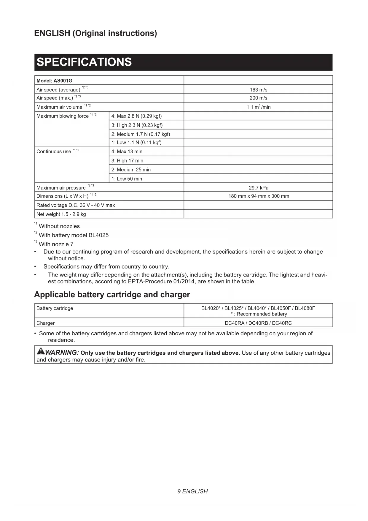
| Dimensions (L x W x H) | 180 mm x 94 mm x 300 mm |
| Net weight | 1.5 - 2.9 kg (depending on battery and accessory) |
| Power supply | Lithium-ion battery 36 V - 40 V max DC |
| Compatible batteries | BL4020, BL4025, BL4040, BL4050F, BL4080F |
| Compatible charger | DC40RA, DC40RB, DC40RC |
| Max air volume | 1.1 m³/min (Max mode without nozzle) |
| Max air pressure | 29.7 kPa |
| Max air speed | 200 m/s |
| Sound level | 82 dB(A) (pressure) / 90 dB(A) (power) |
| Main functions | Blowing, inflating and deflating of inflatable objects |
| Included nozzles | Nozzle 3, Nozzle 7, Nozzle 13, Wide range nozzle, Deformable sleeve nozzle, Flexible hose 6 |
| Maintenance and cleaning | Clean the sponge filter regularly; wash with water and dry in the shade |
| Safety | Protection against overload, overheating and total discharge; automatic stop |
| Spare parts and repairability | Repairs by authorized Makita service center only |
| General information | Commercial and domestic use |
Frequently Asked Questions - AS001GZ MAKITA
User questions about AS001GZ MAKITA
0 question about this device. Answer the ones you know or ask your own.
Ask a new question about this device
Download the instructions for your Compressor in PDF format for free! Find your manual AS001GZ - MAKITA and take your electronic device back in hand. On this page are published all the documents necessary for the use of your device. AS001GZ by MAKITA.
USER MANUAL AS001GZ MAKITA
Without nozzles
^2 With battery model BL4025
+3 With nozzle 7
- Due to our continuing program of research and development, the specifications herein are subject to change without notice.
- Specifications may differ from country to country.
The weight may differ depending on the attachment(s), including the battery cartridge. The lightest and heaviest combinations, according to EPTA-Procedure 01/2014, are shown in the table.
Applicable battery cartridge and charger
| Battery cartridge | BL4020* / BL4025* / BL4040* / BL4050F / BL4080F *: Recommended battery |
| Charger | DC40RA / DC40RB / DC40RC |
- Some of the battery cartridges and chargers listed above may not be available depending on your region of residence.
WARNING: Only use the battery cartridges and chargers listed above. Use of any other battery cartridges and chargers may cause injury and/or fire.
Applicable nozzles and attachments
| Nozzles and attachments Applications and purposes Diameters | ||
| Nozzle 3 | Blowing air into confined spaces, corners, and spaces by the walls to dust off. | ø3.0 mm |
| Nozzle 7 | Dusting off filters.ø7.0 mm | |
| Nozzle 13 | Using as blower Cleaning work surfaces and blowing dust in general. Anchor hole cleaning with optional long nozzles. Functioning as a joint between long nozzles and blower outlet of the tool. Using as inflator Inflating large inflatable pools or air mattresses. Using as deflator Deflating large inflatable pools or air mattresses. Functioning as a joint between air vent hose complete and rubber attachments. | ø13 mm |
| Wide range nozzle | Blowing air over dirt and liquid on desktop and wide-open area. Blowing range: 120° with 5 holes | ø6.0 mm * As a single hole diameter |
| Pinch valve nozzle | Inflating/deflating beach toys, pillows, and similar plastic inflatables. * Deflating operation can be carried out with optional air vent hose complete. | ø7.0 mm |
| Flexible nozzle 6 | Blowing dust out of any hard-to-reach spots, PCs and similar devices.ø6.0 mm x 800 mm | |
| Nozzles and attachments Appli-cations and purposes Diameters | ||
| Long nozzles set | A set of nozzles suitable for blowing dust out of anchor holes and narrow spots. Nozzle lengths can be changed by attaching and detaching two nozzle heads.* Long nozzles can be installed using nozzle 13 as a joint. | ø8.0 mm |
| Air vent hose complete | Deflating inflatable items with appropriate nozzles in operation. - | |
| Rubber attachment 20 - 30 | Nozzle head suitable for deflating air mattress, raft, boat, and pool.* This attachment requires to be installed with the air vent hose complete and nozzle 13 together. | ø20 - 30 mm* Measured as outer diameter. |
| Rubber attachment 65 | Attachment suitable for packaging your clothes by compressing air out of them.* This attachment requires to be installed with the air vent hose complete and nozzle 13 together. | ø65 mm |
| Filter C | Attachment designed to reduce dust intake into the motor under dusty working conditions. | - |
Symbols
The followings show the symbols which may be used for the equipment. Be sure that you understand their meaning before use.

Read instruction manual.

Keep hands away from rotating parts.

Long hair may cause entanglement accident.


Keep bystanders away.

Wear eye and ear protection.

Do not expose to moisture.

Ni-MH Li-ion
Only for EU countries
Due to the presence of hazardous components in the equipment, waste electrical and electronic equipment, accumulators and batteries may have a negative impact on the environment and human health. Do not dispose of electrical and electronic appliances or batteries with household waste!
In accordance with the European Directive on waste electrical and electronic equipment and on accumulators and batteries and waste accumulators and batteries, as well as their adaptation to national law, waste electrical equipment, batteries and accumulators should be stored separately and delivered to a separate collection point for municipal waste, operating in accordance with the regulations on environmental protection.
This is indicated by the symbol of the crossed-out wheeled bin placed on the equipment.
Intended use
The tool is intended for blowing dust, inflating and deflating inflatable, with changeable nozzles according to your preferences. Suitable for both commercial and home use, e.g., cleaning work spaces, dusting filters, and inflating beach toys.
Noise
The typical A-weighted noise level determined according to EN62841-1:
NOTE: The declared noise emission value(s) has been measured in accordance with a standard test method and may be used for comparing one tool with another.
NOTE: The declared noise emission value(s) may also be used in a preliminary assessment of exposure.

WARNING: Wear ear protection.

WARNING: The noise emission during actual use of the power tool can differ from the declared value(s) depending on the ways in which the tool is used especially what kind of workpiece is processed.

WARNING: Be sure to identify safety measures to protect the operator that are based on an estimation of exposure in the actual conditions of use (taking account of all parts of the operating cycle such as the times when the tool is switched off and when it is running idle in addition to the trigger time).
Vibration
The vibration total value (tri-axial vector sum) determined according to EN62841-1:
Work mode: operation without load
Vibration emission (a_h):2.5m / s^2 or less
Uncertainty (K): 1.5m / s^2
NOTE: The declared vibration total value(s) has been measured in accordance with a standard test method and may be used for comparing one tool with another.
NOTE: The declared vibration total value(s) may also be used in a preliminary assessment of exposure.

WARNING: The vibration emission during actual use of the power tool can differ from the declared value(s) depending on the ways in which the tool is used especially what kind of workpiece is processed.

WARNING: Be sure to identify safety measures to protect the operator that are based on an estimation of exposure in the actual conditions of the site (taking account of all parts of the operating cycle such as the times when the tool is switched off and when it is running idle in addition to the trigger time).
Declarations of Conformity
For European countries only
The Declarations of conformity are included in Annex A to this instruction manual.
SAFETYWARNINGS
General power tool safety warnings

WARNING Read all safety warnings, instructions, illustrations and specifications provided with this power tool. Failure to follow all instructions listed now may result in electric shock, fire and/or serious injury.
Save all warnings and instructions for future reference.
The term "power tool" in the warnings refers to your mains-operated (corded) power tool or battery-operated (cordless) power tool.
Cordless Dust Blower Safety Instructions
Training
- Read the instructions carefully. Be familiar with the controls and the correct use of the dust blower.
- Never allow children, persons with reduced physical, sensory or mental capabilities or lack of experience and knowledge or people unfamiliar with these instructions to use the dust blower. Local regulations may restrict the age of the operator.
- Never operate the dust blower while people, especially children, or pets are nearby.
- Keep in mind that the operator or user is responsible for accidents or hazards occurring to other people or their property.
Preparation
- Do not wear loose clothing or jewellery that can be drawn into the air inlet. Keep long hair away from the air inlets.
- To prevent dust irritation the wearing of a face mask is recommended.
- Use personal protective equipment. Always wear eye protection. Protective equipment such as a dust mask, non-skid safety shoes, hard hat or hearing protection used for appropriate conditions will reduce personal injuries.
Operation in general
- Switch off the dust blower and remove the battery cartridge and make sure that all moving parts have come to a complete stop
whenever you leave the dust blower.
whenever you switch from inflating to deflating operation, and vice versa. - before checking, cleaning or working on the dust blower.
- if the dust blower starts to vibrate abnormally.
- Operate the dust blower only in daylight or in good artificial light.
- Do not overreach and keep proper balance and footing at all times.
- Keep all cooling air inlets clear of debris.
- Operate the dust blower in a recommended position and on a firm surface.
- Do not use the tool with wet hands.
- Do not point the outlet of the nozzle and attachment to yourself or others. Objects may be blown away and cause an injury.
- Do not use the tool to spray chemicals. Your lungs may be damaged by inhaling toxic fumes.
- Do not operate the dust blower at high places.
-
Never block suction inlet and/or blower outlet.
-
Be careful not to block suction inlet or blower outlet with dust or dirt when operating in dusty area.
-
Do not use nozzles other than the nozzles provided by Makita.
-
If the dust blower strikes any foreign objects or should start making any unusual noise or vibration, immediately switch off the dust blower to stop it. Remove the battery cartridge from the dust blower and inspect the dust blower for damage before restarting and operating the dust blower. If the dust blower is damaged, ask Makita Authorized Service Centers for repair.
- Do not insert fingers or other objects into suction inlet or blower outlet.
- Prevent unintentional starting. Ensure the switch is in the off-position before inserting battery cartridge, picking up or carrying the dust blower. Carrying the dust blower with your finger on the switch or energizing the dust blower that has the switch on invites accidents.
- Avoid operating the dust blower for a long time in low temperature environment.
- Do not use the tool beyond the maximum output pressure of the tool. Using the tool at output pressure greater than the maximum output pressure of the tool may burst the object or the tool.
Blowing operation
- Never blow debris in the direction of bystanders.
- Never point the nozzle at anyone in the vicinity when using the dust blower.
- Never blow dangerous materials, such as nails, fragments of glass, or blades.
- Do not operate the dust blower near flammable materials.
Inflating/Deflating operation
- When inflating objects, connect a nozzle or attachment to the air inlet securely. Otherwise, the object, nozzle, or attachment may be damaged and you may be injured.
- Release air pressure slowly. When removing a nozzle or attachment after inflating objects, hold the object, nozzle and attachment firmly. They may bounce due to exhaust air and cause an injury.
- Do not inflate object beyond the maximum pressure of the object. Otherwise, the tool or object may be damaged and you may be injured.
- Inflate the objects intended to be inflated by the manufacturer only, such as beach toys or air mattress. Inflating other objects may damage them and cause an injury.
- When inflating objects, check the status of the tool and object, and be sure that there is no air leak from the object.
- Always be careful not to over-inflate objects during operation. It otherwise may burst the objects, possibly causing damage to the tool and personal injury.
- After inflating objects, check the air pressure using a reliable and calibrated measuring equipment.
- Never leave the tool unattended when the nozzle or attachment is attached to the object or during operation.
-
Do not use the tool as a vacuum cleaner. Performing dust collection may damage the tool.
-
Do not use the tool as a breathing device.
- Use only standard accessories provided by Makita. The use of any other accessories or attachments might present a risk of injury to persons.
Maintenance and storage
- Keep all nuts, bolts and screws tight to be sure the dust blower is in safe working condition.
- If the parts are worn or damaged, replace them with parts provided by Makita.
- Store the dust blower in a dry place out of the reach of children.
- When you stop the dust blower for inspection, servicing, storage, or changing accessory, switch off the dust blower and make sure that all moving parts come to a complete stop, and remove the battery cartridge. Cool down the dust blower before making any work on the dust blower. Maintain the dust blower with care and keep it clean.
- When carrying the tool, do not hold or pull a nozzle or attachment. The tool may be damaged and cause an injury.
- Always cool down the dust blower before storing.
- Do not expose the dust blower to rain. Store the dust blower indoors.
- Do not disassemble the tool.
Service
- Have your power tool serviced by a qualified repair person using only identical replacement parts. This will ensure that the safety of the power tool is maintained.
- Never service damaged battery packs. Service of battery packs should only be performed by the manufacturer or authorized service providers.
SAVE THESE INSTRUCTIONS.
WARNING: DO NOT let comfort or familiarity with product (gained from repeated use) replace strict adherence to safety rules for the subject product.
MISUSE or failure to follow the safety rules stated in this instruction manual may cause serious personal injury.
Important safety instructions for battery cartridge
- Before using battery cartridge, read all instructions and cautionary markings on (1) battery charger, (2) battery, and (3) product using battery.
- Do not disassemble or tamper with the battery cartridge. It may result in a fire, excessive heat, or explosion.
- If operating time has become excessively shorter, stop operating immediately. It may result in a risk of overheating, possible burns and even an explosion.
-
If electrolyte gets into your eyes, rinse them out with clear water and seek medical attention right away. It may result in loss of your eyesight.
-
Do not short the battery cartridge:
(1) Do not touch the terminals with any conductive material.
(2) Avoid storing battery cartridge in a container with other metal objects such as nails, coins, etc.
(3) Do not expose battery cartridge to water or rain.
A battery short can cause a large current flow, overheating, possible burns and even a breakdown.
- Do not store and use the tool and battery cartridge in locations where the temperature may reach or exceed 50^ (122^) .
- Do not incinerate the battery cartridge even if it is severely damaged or is completely worn out. The battery cartridge can explode in a fire.
-
Do not nail, cut, crush, throw, drop the battery cartridge, or hit against a hard object to the battery cartridge. Such conduct may result in a fire, excessive heat, or explosion.
-
Do not use a damaged battery.
-
The contained lithium-ion batteries are subject to the Dangerous Goods Legislation requirements. For commercial transports e.g. by third parties, forwarding agents, special requirement on packaging and labeling must be observed. For preparation of the item being shipped, consulting an expert for hazardous material is required. Please also observe possibly more detailed national regulations. Tape or mask off open contacts and pack up the battery in such a manner that it cannot move around in the packaging.
- When disposing the battery cartridge, remove it from the tool and dispose of it in a safe place. Follow your local regulations relating to disposal of battery.
- Use the batteries only with the products specified by Makita. Installing the batteries to non-compliant products may result in a fire, excessive heat, explosion, or leak of electrolyte.
- If the tool is not used for a long period of time, the battery must be removed from the tool.
- During and after use, the battery cartridge may take on heat which can cause burns or low temperature burns. Pay attention to the handling of hot battery cartridges.
- Do not touch the terminal of the tool immediately after use as it may get hot enough to cause burns.
- Do not allow chips, dust, or soil stuck into the terminals, holes, and grooves of the battery cartridge. It may cause heating, catching fire, burst and malfunction of the tool or battery cartridge, resulting in burns or personal injury.
- Unless the tool supports the use near high-voltage electrical power lines, do not use the battery cartridge near high-voltage electrical power lines. It may result in a malfunction or breakdown of the tool or battery cartridge.
- Keep the battery away from children.
SAVE THESE INSTRUCTIONS.
CAUTION: Only use genuine Makita batteries. Use of non-genuine Makita batteries, or batteries that have been altered, may result in the battery bursting causing fires, personal injury and damage. It will also void the Makita warranty for the Makita tool and charger.
Tips for maintaining maximum battery life
- Charge the battery cartridge before completely discharged. Always stop tool operation and charge the battery cartridge when you notice less tool power.
- Never recharge a fully charged battery cartridge. Overcharging shortens the battery service life.
- Charge the battery cartridge with room temperature at 10^ - 40^ (50°F - 104°F). Let a hot battery cartridge cool down before charging it.
- When not using the battery cartridge, remove it from the tool or the charger.
- Charge the battery cartridge if you do not use it for a long period (more than six months).
ASSEMBLY
CAUTION: Always be sure that the tool is switched off and the battery cartridge is removed before carrying out any work on the tool.
Installing nozzle
Align the guide projections on a nozzle with the locking notches on the lock sleeve of the tool, then push the nozzle firmly into the lock sleeve until it locks in place with a click. Having installed the nozzle, try pulling it back to ensure it is securely held in place.
Fig.1: 1. Guide projections 2. Locking notches 3. Lock sleeve
NOTICE: Make sure that the nozzle has been correctly attached to the tool so the guide projections on the nozzle neatly fit into the locking notches on the lock sleeve.
Removing nozzle
Hold the nozzle end and rotate it in a direction indicated by the arrows on the nozzle end to release the lock. Pull the nozzle apart from the lock sleeve after it becomes unlocked.
Fig.2: 1. Nozzle end 2. Lock sleeve
NOTICE: Adhered dirt and dust on the surface will possibly make it hard to remove the nozzle from the tool. In such a case, slide and hold the lock sleeve towards the motor housing first, and then turn the nozzle end to release the lock.
CAUTION: Be careful not to pinch your hands between the rear end of the lock sleeve and motor housing while removing the nozzle. The lock sleeve slides back towards the motor housing when the nozzle is released from the lock.
Fig.3: 1. Lock sleeve 2. Motor housing
Removing and installing dust cap
- Turn the dust cap on the suction inlet at the rear of the housing counterclockwise to take the dust cap out of the housing. Two locking tabs on the dust cap can be disengaged by aligning them with the guide grooves on the housing.
Fig.4: 1. Dust cap 2. Locking tabs 3. Suction inlet 4. Guide grooves - Reassemble the dust cap onto the suction inlet, aligning the two locking tabs on the dust cap with the guide grooves on the housing. Then turn the dust cap clockwise to secure it in place.
Fig.5: 1. Dust cap 2. Locking tabs 3. Suction inlet 4. Guide grooves
Installing and removing long nozzles
Optional accessory
A set of long nozzles help clean dust out of small holes and narrow spots. Nozzle lengths can be arranged according to your requirements.
Fig.6: 1. Nozzle 13 2. Long nozzle R 3. Long nozzle F
- Insert the long nozzle R through the air hole of the nozzle 13 from back to front. Pass it though until the nozzle 13 secures in place at the rear end of the long nozzle R.
Fig.7: 1. Nozzle 132. Long nozzle R -
Place the long nozzle F over the front end of the long nozzle R. Hand screw the long nozzle F until you find it roughly tightened, then re-tighten it securely.
Fig.8: 1. Long nozzle F 2. Long nozzle R -
Align the guide projections on the nozzle 13 with the locking notches on the lock sleeve of the tool, then push the nozzle 13 firmly into the lock sleeve until it locks in place with a click.
Fig.9: 1. Guide projection 2. Locking notch 3. Lock sleeve 4. Nozzle 13 5. Long nozzle R 6. Long nozzle F
NOTE: Use the long nozzle R only to have a shorter operating range. Use both the long nozzle R and F to allow a wider operating range.
- To remove the long nozzles, detach the nozzle 13 from the lock sleeve of the tool, and then disassemble the long nozzles.
Installing and removing deflating nozzles and attachments
Optional accessory
NOTICE: Always be sure to install and uninstall deflating nozzles and attachments only while the air vent hose complete is disconnected from the tool. Handling the air vent hose complete assembled into the tool may cause the tool to stand unstable resulting in it falling over.
- Align the guide projections on the pinch valve nozzle with the locking notches on the lock sleeve of the air vent hose complete, then push the pinch valve nozzle firmly into the lock sleeve until it locks in place with a click.
Fig.10: 1. Pinch valve nozzle 2. Guide projections 3. Locking notches 4. Lock sleeve 5. Air vent hose complete
Optional rubber attachments
Optional rubber attachments require to be placed over the nozzle. Be careful not to attach rubber attachments directly to the air vent hose complete.
i Align the guide projections on the nozzle 13 with the locking notches on the lock sleeve of the air vent hose complete, then push the nozzle firmly into the lock sleeve until it locks in place with a click.
ii Place a rubber attachment over the nozzle head by pushing and hand screwing it in place.
Fig.11: 1. Rubber attachments 2. Nozzle 13 3. Air vent hose complete
NOTICE: Make sure that the nozzle has been correctly attached to the air vent hose complete so the guide projections on the nozzle neatly fit into the locking notches on the lock sleeve.
- Turn the dust cap on the suction inlet at the rear of the housing counterclockwise to take the dust cap out of the housing. Two locking tabs on the dust cap can be disengaged by aligning them with the guide grooves on the housing.
Fig.12: 1. Dust cap 2. Locking tabs 3. Suction inlet 4. Guide grooves
3. Attach the end of the air vent hose complete to the suction inlet, aligning the two locking tabs on the air vent hose complete with the guide grooves on the housing. Then hold and turn the rear cuffs of the air vent hose complete clockwise to secure it in place.
Fig.13: 1. Air vent hose complete 2. Rear cuffs 3. Suction inlet 4. Locking tabs 5. Guide grooves
4. To remove the deflating nozzle and attachments, follow the installation steps in reverse.
NOTICE: Always hold and turn the rear cuffs of the air vent hose complete to install and uninstall the air vent hose complete in place.
Installing optional filter
Optional accessory
An optional high performance filter (Filter C) is available for restricting dust intake into the motor under dusty working conditions.
- Turn the dust cap on the suction inlet at the rear of the housing counterclockwise to take the dust cap out of the housing. Two locking tabs on the dust cap can be disengaged by aligning them with the guide grooves on the housing.
Fig.14: 1. Dust cap 2. Locking tabs 3. Suction inlet 4. Guide grooves - Replace an optional high performance filter on the suction inlet, aligning the two locking tabs on the optional filter with the guide grooves on the housing. Then turn the optional filter clockwise to secure it in place.
Fig.15: 1. Optional high performance filter 2. Locking tabs 3. Suction inlet 4. Guide grooves
NOTICE: An optional high performance filter (Filter C) can be reused many times by cleaning it out. Clean dust off the filter regularly as a clogged filter may block the airflow and cause less efficient operation. Occasionally wash the filter in water, rinse and dry thoroughly in the shade before use.
NOTICE: Do not wipe, rub or scratch an optional high performance filter (Filter C) hardly. Be sure to shake or blow dust off the filter with care.
FUNCTIONAL DESCRIPTION
CAUTION: Always be sure that the tool is switched off and the battery cartridge is removed before adjusting or checking function on the tool.
Installing or removing battery cartridge
CAUTION: Always switch off the tool before installing or removing of the battery cartridge.
CAUTION: Hold the tool and the battery cartridge firmly when installing or removing battery cartridge. Failure to hold the tool and the battery cartridge firmly may cause them to slip off your hands and result in damage to the tool and battery cartridge and a personal injury.
Fig.16: 1. Red indicator 2. Button 3. Battery cartridge
To remove the battery cartridge, slide it from the tool while sliding the button on the front of the cartridge.
To install the battery cartridge, align the tongue on the battery cartridge with the groove in the housing and slip it into place. Insert it all the way until it locks in place with a little click. If you can see the red indicator as shown in the figure, it is not locked completely.
CAUTION: Always install the battery cartridge fully until the red indicator cannot be seen. If not, it may accidentally fall out of the tool, causing injury to you or someone around you.
CAUTION: Do not install the battery cartridge forcibly. If the cartridge does not slide in easily, it is not being inserted correctly.
Indicating the remaining battery capacity
Press the check button on the battery cartridge to indicate the remaining battery capacity. The indicator lamps light up for a few seconds.
Fig.17: 1. Indicator lamps 2. Check button
| Indicator lamps Remaining | capacity | ||
| Lighted Off | Blinking | ||
| 75% to 100% | |||
| 50% to 75% | |||
| 25% to 50% | |||
| 0% to 25% | |||
| Charge the battery. | |||
| The battery may have malfunctioned. | |||
NOTE: Depending on the conditions of use and the ambient temperature, the indication may differ slightly from the actual capacity.
NOTE: The first (far left) indicator lamp will blink when the battery protection system works.
Tool / battery protection system
The tool is equipped with a tool/battery protection system. This system automatically cuts off power to the motor to extend tool and battery life. The tool will automatically stop during operation if the tool or battery is placed under one of the following conditions:
Overload protection
When the tool/battery is operated in a manner that causes it to draw an abnormally high current, the tool stops automatically. In this situation, turn the tool off and stop the application that caused the tool to become overloaded. Then turn the tool on to restart.
Overheat protection
When the tool/battery is overheated, the tool stops automatically. In this situation, let the tool cool down before turning the tool on again.
Overdischarge protection
When the battery capacity is not enough, the tool stops automatically and the lamp will blink. In this case, remove the battery from the tool and charge the battery.
Protections against other causes
Protection system is also designed for other causes that could damage the tool and allows the tool to stop automatically. Take all the following steps to clear the causes, when the tool has been brought to a temporary halt or stop in operation.
- Turn the tool off, and then turn it on again to restart.
- Charge the battery(ies) or replace it/them with recharged battery(ies).
- Let the tool and battery(ies) cool down.
If no improvement can be found by restoring protection system, then contact your local Makita Service Center.
Switch action
CAUTION: Before installing the battery cartridge into the tool, always check to see that the switch trigger actuates properly and returns to the "OFF" position when released.
CAUTION: Switch can be locked in "ON" position for ease of operator comfort during extended use. Apply caution while locking tool in "ON" position.
CAUTION: Do not install the battery cartridge with the lock-on button engaged.
CAUTION: When not operating the tool, depress the trigger-lock button from the side on which a locking mark (B) is indicated to lock the switch trigger in the "OFF" position.
Trigger-lock button
To prevent the switch trigger from being accidentally pulled, the trigger-lock button is provided. To start the tool, depress the trigger-lock button from the side on which an unlocking mark (this indicated. To lock the tool, depress the trigger-lock button from the side on which a locking mark (this indicated. Make sure to set the trigger-lock button back in a locking position after each use.
Fig.18: 1. Switch trigger 2. Trigger-lock button
3. Unlocking mark 4. Locking mark
NOTICE: Do not pull the switch trigger hard without releasing the trigger-lock button. This can cause switch breakage.
Switch trigger
Air volume can be controlled by squeezing the switch trigger. Air volume is grown by increasing pressure on the switch trigger. Release the switch trigger to stop.
Fig.19: 1. Switch trigger
Lock button
For continuous operation, push in the lock button while pulling the switch trigger and then release the switch trigger. To cancel the locked-on operation, pull the switch trigger fully, then release it.
Fig.20: 1. Switch trigger 2. Lock button
Adjusting air volume
Air volume can be changed in four modes, that is, 4 (Max), 3 (High), 2 (Medium) and 1 (Low), depending on the application and workload.
Press the air volume adjustment button to switch mode in the following sequence. The mode changes every time you press the button.
Fig.21: 1. Low air volume 2. Medium air volume 3. High air volume 4. Max air volume 5. Air volume adjustment button
Air volume settings table
| Air volume mode Maximum air volume | |
| 4: Max 1.1 m | 3/min |
| 3: High 1.0 m | 3/min |
| 2: Medium 0.8 m | 3/min |
| 1: Low 0.6 m | 3/min |
- Maximum air volumes are measured without nozzles.
NOTE: Air volume mode can be changed before turning the tool on.
NOTE: The tool starts operation with the last air volume mode settings in use.
Lighting up the lamp
CAUTION: Do not look in the light or see the source of light directly.
To turn the lamp on, perform one of the following steps.
- Pull the switch trigger to light the lamp up. The lamp keeps on lighting while the switch trigger is being pulled. The lamp goes out approximately 10 seconds after stopping operation.
- Press the air volume adjustment button. The lamp goes off in approximately 10 seconds.
NOTE: When the remaining battery capacity gets low, the lamp starts blinking. The timing, at which the lamp starts blinking depends on the temperature at work place and the battery cartridge conditions.
▶ Fig.22: 1. Switch trigger 2. Air volume adjustment button 3. Lamp
Hanging hole
CAUTION: Before hanging the tool, always make sure that the hanging hole is not damaged.
CAUTION: Use the hanging/mounting parts for their intended purposes only. Using for unintended purpose may cause accident or personal injury.
CAUTION: Withstanding load rated for your tools racks and holders needs to be learned beforehand. Do not place the tool if it exceeds the withstanding load on the racks and holders.
CAUTION: Be sure that the hanging hole is securely hooked before releasing your hold.
Use the hanging hole at the top rear of the housing to hang the tool on a hook of racks and holders.
Fig.23: 1. Hanging hole 2. Hook
Installing hook
Optional accessory
WARNING: Use the hanging/mounting parts for their intended purposes only, e.g., hanging the tool on a tool belt between jobs or work intervals.
WARNING: Be careful not to overload the hook as too much force or irregular overburden may cause damages to the tool resulting in personal injury.
CAUTION: When installing the hook, always secure it with the screw firmly. If not, the hook may come off from the tool and result in the personal injury.
CAUTION: Make sure to hang the tool securely before releasing your hold. Insufficient or unbalanced hooking may cause falling off and you may be injured.
Fig.24: 1. Groove 2. Hook 3. Screw
The hook is convenient for temporarily hanging the tool. This can be installed on either side of the tool. To install the hook, insert it into a groove in the tool housing on either side and then secure it with a screw. To remove, loosen the screw and then take it out.
OPERATION
CAUTION: Do not point the nozzle at anyone nearby during operation.
NOTICE: Do not block suction inlet and/or blower outlet during operation.
Blowing in general use
Recommended nozzles
- Nozzle 13
Clean your work surfaces and floors by blowing off dust, dirt, debris, scrap or waste in general.
Direct the nozzle towards surfaces at an appropriate distance and swing it around to blow off entirely.
Fig.25
CAUTION: Never blow debris in the direction of bystanders or pets.
CAUTION: Use personal protective equipment such as a dust mask and eye protection.
NOTICE: Remove blockages on surfaces away before blowing operation.
Blowing in confined spaces
Recommended nozzles
- Nozzle 3
Blow into confined spots, corners, and spaces by the walls to dust off.
Point the nozzle straight at spaces at a reasonable distance and squeeze the switch trigger to control blowing air volume.
Fig.26
Fig.27
CAUTION: Keep the nozzle away a reasonable distance from blowing spots to avoid blowing up dust into the air.
CAUTION: Use personal protective equipment such as a dust mask and eye protection.
NOTICE: Avoid blocking the air vent holes around the blower outlet. It otherwise may cause sudden noise and vibrations and could possibly affect the tool performance.
Fig.28: 1. Air vent holes 2. Blower outlet
Dusting air filter
Recommended nozzles
Nozzle 7
Dust filter surfaces by blowing air through one side of the filter to the other.
Direct the nozzle on filter surfaces within a short distance and swing it from side to side to blow dust away from surfaces.
Fig.29
CAUTION: Use personal protective equipment such as a dust mask and eye protection.
NOTE: Point the nozzle at an angle according to the outlines of the filter so the adhered dust can be easily removed.
Blowing wide and open area
Recommended nozzles
Wide range nozzle
Blow air over dirt and liquid on wide-open surfaces such as desktop and floor, using the five-hole nozzle with 120 degree range of blowing.
Direct the nozzle over a large area within a certain distance and swing it back and forth and from side to side to blow widely.
Fig.30
CAUTION: Use personal protective equipment such as a dust mask and eye protection.
Inflating plastic inflatableables
Recommended nozzles
Pinch valve nozzle
— Nozzle 13
Inflatable air volume with fully charged battery cartridge BL4025 without recharging it
| Air volume mode | Inflatable air volume (With pinch valve nozzle) | Number ofø61 cm plastic beach balls equivalent in air volume (With pinch valve nozzle) |
| 4: Max 8.9 m | 3 | 75 |
| 3: High 9.5 m | 3 | 80 |
| 2: Medium 13.0 m | 3 | 110 |
| 1: Low 21.3 m | 3 | 180 |
NOTE: The maximum output air pressure of this tool is 20.6kPa (With nozzle 13)
Inflate beach toys, pillows, and similar small plastic inflatable with pinch valve nozzle.
Inflate garden pools, air mattresses, and similar large plastic inflatableables with nozzle 13.
Insert the nozzle into an air inlet on an inflatable item and pull the switch trigger to start inflating.
Slowly release the switch trigger to reduce air volume as the inflatable item comes close to fully inflated.
Remove the nozzle from the air inlet after stopping the air flow and then close the air inlet.
Fig.31
Fig.32
CAUTION: Always be careful not to over-inflate inflatables during operation. It otherwise may burst the inflatables, possibly causing damage to the tool and personal injury.
CAUTION: Never leave the tool unattended while the nozzle is attached to inflatable or during operation.
CAUTION: Be aware that heated air stream may flow through the air vent hole at bottleneck of the pinch valve nozzle due to air circulation.
NOTE: Make sure to insert the pinch valve nozzle fully through the air inlet so the nozzle head serves to open the flap valve inside the air inlet.
NOTE: For an inflatable item with a small air inlet opening, insert the narrow tip of the pinch valve nozzle in the air inlet until the bottleneck of the nozzle head touches the rim of the air inlet.
NOTE: For an inflatable item with a large air inlet opening, insert the pinch valve nozzle head fully into the air inlet to open the flap valve inside the air inlet.
Fig.33: 1. Flap valve 2. Small air inlet opening 3. Large air inlet opening 4. Bottleneck 5. Air vent hole
NOTE: If an air inlet on an inflatable item is relatively smaller than the pinch valve nozzle head, squeeze and enlarge the air inlet by hand and then twist and hold the nozzle head into the air inlet.
Blowing in holes and narrow spots
Optional accessory
Recommended nozzles
Long nozzles set
Clean dust out of small holes and narrow spots. Nozzle lengths can be arranged according to your requirements.
Assemble the long nozzle R and F together to allow a longer operating range, for instance, cleaning anchor holes at your feet.
Fig.34
Use the long nozzle R only to have a shorter operating range, for instance, cleaning spots on the wall.
Fig.35
CAUTION: Use personal protective equipment such as a dust mask and eye protection.
Blowing in narrow spaces
Optional accessory
Recommended nozzles
Flexible nozzle 6
Blow dust out of any hard-to-reach spots. Highly effective for engine cleaning, in-car dust removal, computer case dust blowing.
Point the nozzle at an angle within touching distance, and blow back and forth to clean out lingering dust. Change angles of the nozzle as you blow off to help blow out some of the tougher pieces of debris and dust.
Fig.36
CAUTION: Use personal protective equipment such as a dust mask and eye protection.
NOTICE: Avoid blocking the air vent holes around the flexible hose end. It otherwise may cause sudden noise and vibrations and could possibly affect the tool performance.
Fig.37: 1. Air vent holes
Deflating plastic inflatableables
Optional accessory
NOTICE: Avoid deflating inflatable items in wet and dusty conditions since water, dust, and similar external substances on surfaces may reach into the motor causing damages to the tool. Dry and clean inflatablees off thoroughly before performing deflating operation.
NOTICE: Never leave the tool unattended while deflating inflatable. Running the motor continuously after deflation is completed may cause overheating.
Recommended nozzles and attachments
Air vent hose complete
Pinch valve nozzle
Rubber attachment 20 - 30
Rubber attachment 65
-
Deflate inflatable items with proper nozzles according to your preferences and applications.
-
Place a nozzle or rubber attachment onto the air vent hose complete.
- Replace the dust cap on the suction inlet of the tool with the air vent hose complete.
- Insert the nozzle into the air valve or place the attachment over the air valve on inflatable items, and pull the switch trigger to start deflating.
- Slowly release the switch trigger to reduce suction volume as an inflatable item comes close to fully deflated.
- Remove the nozzle or attachment from the air valve after stopping the air flow and then close the air valve.
With pinch valve nozzle
Fig.38
With rubber attachment 20 - 30
Fig.39
With rubber attachment 65
Fig.40
MAINTENANCE
CAUTION: Always be sure that the tool is switched off and the battery cartridge is removed before attempting to perform inspection or maintenance.
To maintain product SAFETY and RELIABILITY, repairs, any other maintenance or adjustment should be performed by Makita Authorized or Factory Service Centers, always using Makita replacement parts.
NOTICE: Never use gasoline, benzine, thinner, alcohol or the like. Discoloration, deformation or cracks may result.
Cleaning
Cleaning body
Clean the body of your tool with a dry cloth or cloth dampened in soapy water at regular intervals.
Cleaning nozzles
Clear clogs or dust that block the openings of nozzles before and after each use.
Removing and installing filter
CAUTION: After cleaning filter, be sure to reassemble it in the correct position.
-
Clean the filter at regular intervals since using a clogged filter may result in poor suction performance.
-
Turn the dust cap on the suction inlet at the rear of the housing counterclockwise to take the dust cap out of the housing. Two locking tabs on the dust cap can be disengaged by aligning them with the guide grooves on the housing.
Fig.41: 1. Dust cap 2. Locking tabs 3. Suction inlet 4. Guide grooves
- Take the circular sponge filter B (black gray) out of the suction inlet.
Fig.42: 1. Circular sponge filter B (black gray)
Do not remove the sponge filter A (yellow) placed further inside the suction inlet as it needs to be positioned to protect the motor from any damage.
Fig.43: 1. Sponge filter A (yellow)
- Wipe and shake dust off circular sponge filter B by hand. Occasionally wash the filter in water, rinse and dry thoroughly in the shade before use.
Fig.44
Fig.45
NOTICE: Having washed in water, dry the circular sponge filter B up before installing. An insufficiently dried filter may shorten the service life of the motor.
NOTICE: Never wash filters in a washing machine.
NOTICE: Do not rub or scratch filters with hard objects such as a brush.
NOTE: Filters wear out in course of time. It is recommended to have some spares for them.
- Set the circular sponge filter B back over the suction inlet.
Fig.46: 1. Circular sponge filter B
- Reassemble the dust cap onto the suction inlet, aligning the two locking tabs on the dust cap with the guide grooves on the housing. Then turn the dust cap clockwise to secure it in place.
Fig.47: 1. Dust cap 2. Locking tabs 3. Suction inlet 4. Guide grooves
TROUBLESHOOTING
Before asking for repairs, conduct your own inspection first. If you find a problem that is not explained in the manual, do not attempt to dismantle the machine. Instead, ask Makita Authorized Service Centers, always using Makita replacement parts for repairs.
| State of abnormality Probable cause | (malfunction) Remedy | |
| Motor does not run. Battery cartridge is not installed. Install the battery cartridge. | Battery problem (under voltage) Recharge | the battery. If recharging is not effective, replace battery. |
| The drive system does not work correctly. | Ask your local authorized service center for repair. | |
| Motor stops running after a little use. Battery's charge level is low. | Recharge the battery. If recharging is not effective, replace battery. | |
| Overheating. Stop using the tool to cool it down. | ||
| The tool does not reach the maximum air volume. Battery is installed improperly. Install the battery cartridge as described in this manual. | battery system does not work correctly. | |
| Battery power is dropping. Recharge the battery. If recharging is not effective, replace battery. | ||
| The drive system does not work correctly. | Ask your local authorized service center for repair. | |
| Abnormal vibration: stop the tool immediately! | The drive system does not work correctly. | Ask your local authorized service center for repair. |
| Motor cannot stop: Remove the battery immediately! | Electric or electronic malfunction. Remove the battery and ask your local authorized service center for repair. | |
OPTIONAL ACCESSORIES
CAUTION: These accessories or attachments are recommended for use with your Makita product specified in this manual. The use of any other accessories or attachments might present a risk of injury to persons. Only use accessory or attachment for its stated purpose.
If you need any assistance for more details regarding these accessories, ask your local Makita Service Center.
- Nozzle 3
- Nozzle 7
- Nozzle 13
- Wide range nozzle
- Pinch valve nozzle
- Flexible nozzle 6
- Long nozzles set
Air vent hose complete
Rubber attachment 20 - 30
Rubber attachment 65 - Filter C
- Hook
- Makita genuine battery and charger
NOTE: Some items in the list may be included in the product package as standard accessories. They may differ from country to country.
SPECIFICATIONS
Buses et accessoires applicables
Buses et accessoires recommends
ACCESSIONS EN OPTION
VEILIGHEIDSWAAR-SCHUWINGEN
OPTIONELE ACCESSOIRES
Móvo yia xwpe5 ts Eupwnns
Oi Anwoeicuupoppwong Tepiaaavovta oTo Iapaptnma A oTo npov EYxepidio odnyiwv.
ПОНТОИЗEGI
AΣΦΑΛΕΙΑΣ
Evikc ppoedotoinoic aovaaiayia TO nEKTPIKO epvaaleio
A PPOEI OIOIH H IaIaOte oIe TIC TPOEI- 0oioinoeic aopaleiac, odnyie, EIKOVoypapnoeic KAI TPOBIAYPAPcE TOU TApexovTai e auto To nKTPiKO epyAAEO. H mtnpnon oawv twv onyiWv Tou avayapovTai katwtpew mTOpEi va kataanxi OE nKTOPTAnxi, TUPKAYIA n/kai oBapo tpaumatioo.