AC330 - Compressor MAKITA - Free user manual and instructions
Find the device manual for free AC330 MAKITA in PDF.
User questions about AC330 MAKITA
0 question about this device. Answer the ones you know or ask your own.
Ask a new question about this device
Download the instructions for your Compressor in PDF format for free! Find your manual AC330 - MAKITA and take your electronic device back in hand. On this page are published all the documents necessary for the use of your device. AC330 by MAKITA.
USER MANUAL AC330 MAKITA
INSTRUCTION MANUAL AND SAFETY INSTRUCTION
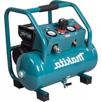
reciprocating piston air compressor oil lubricated
MANUEL D'UTILISATION ET CONSIGNES DE SÉCURITÉ DU COMPRESSEUR
GB WARNING: Please read understand this manual before operating the compressor
Before positioning, operating or adjusting the compressor, read the instruction handbook carefully.
F LIRE LE MANUEL D'INSTRUCTIONS
P LER O MANUAL DE INSTRUÇÕES
Caution: before doing any work on the compressor it must be disconnected from the power supply.
F RISQUE DE DECHARGE ELECTRIQUE
Caution: the compressor contains some parts which might reach high temperatures.
F RISQUE DE TEMPERATURE ELEVEES
Attention, the compressor could start automatically in case of a black-out and subsequent reset.
F RISQUE DE DEPART ACCIDENTEL
S RISK FÖR OFRIVILLIG START
natural_image
Line drawing of a hand operating a pressure relief valve with directional arrows indicating motion (no text or symbols)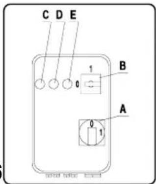
natural_image
Technical illustration of two industrial electric motors with warning symbols (no text or labels present)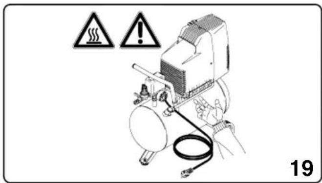
natural_image
Three technical illustrations of an electric motor with windings and a handle, shown from different angles (no text or symbols)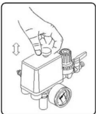
natural_image
Illustration of a hand pressing a pressure regulator component with a valve (no text or symbols)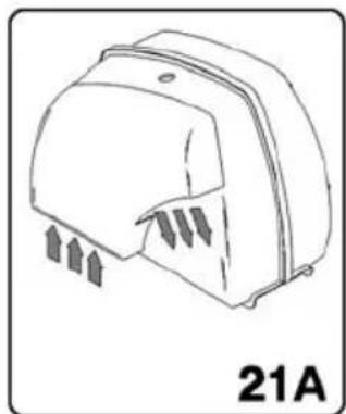
natural_image
Line drawing of a mechanical device with directional arrows indicating movement or force (no text or symbols)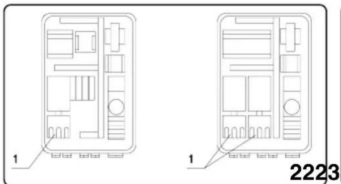
natural_image
Exploded view diagram of an automotive engine assembly showing internal components and assembly steps (no text or labels)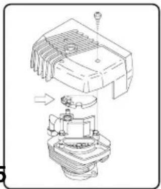
natural_image
Technical line drawing of a mechanical assembly with no visible text or symbols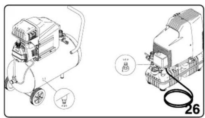
natural_image
Technical line drawing of an air compressor and its electrical housing with a cable (no text or symbols)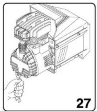
natural_image
Technical line drawing of an electric motor with a hand operating it (no text or symbols)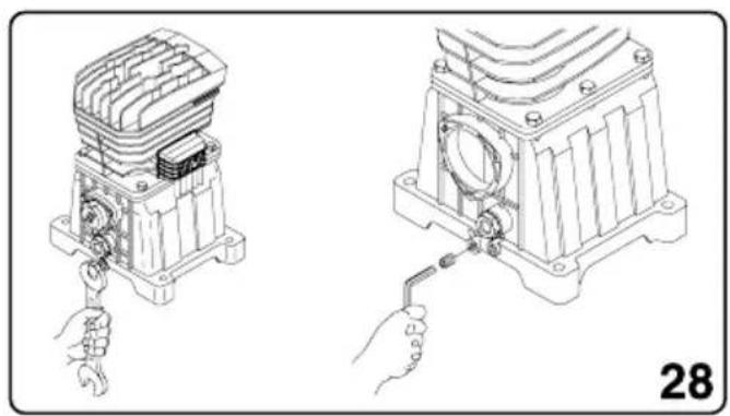
natural_image
Technical line drawing of a mechanical assembly with hands operating it (no text or symbols present)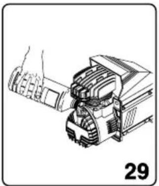
natural_image
Technical line drawing of a mechanical device with gears and a handle, labeled '29' (no text or symbols on the diagram itself)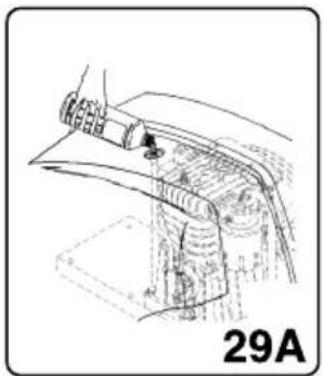
natural_image
Technical line drawing of a mechanical component with no visible text or symbols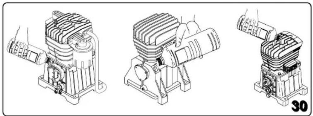
natural_image
Technical line drawings of three industrial motors with no visible text or symbols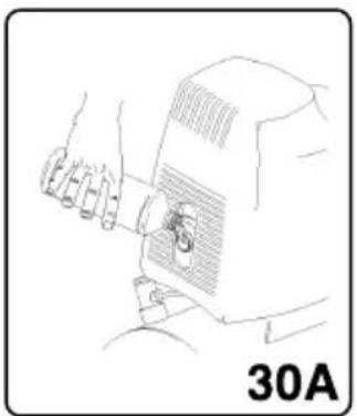
natural_image
Line drawing of a person using a computer mouse, labeled '30A' (no other text or symbols)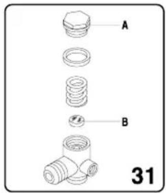
natural_image
Illustration of a person standing next to an electric shock absorber and a small dog, with no visible text or symbols.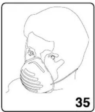
natural_image
Line drawing of a person wearing a face mask and mask (no text or symbols)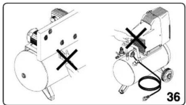
natural_image
Technical line drawing of two industrial equipment setups with no visible text or symbols
natural_image
Line drawing of a person wearing headphones (no text or symbols)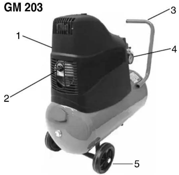
SILENT AB
MOD. GM
- SERBATOIO / TANK / RESERVOIR / KESSEL / TANK / BEHOLDER / DEPÓSITO / DEPÓSITO / SÄILIÖ / TANK
- SCARICO CONDENSA / CONDENSATE DRAIN / EVACUATION CONDENSATION / AUSLASS KONDENSWASSER / AFVOER CONDENSWATER / TÖMNING AF KONDENSVAND / DESAGÜE DEL CONDENSADO / PURGA DA CONDENSAÇÃO / KONDENSSIVEDEN TYHJENNYS / KONDENSVATTNETS AVLOPP
- RUOTA / WHEEL / ROUE / RAD / WIEL / HJUL / RUEDA / RODA / PYÖRÄ / HJUL
- GRUPPO COMPRESSORE / COMPRESSOR UNIT / GROUPE COMPRESSEUR / KOMPRESSORAGGREGAT / COMPRESSOR GROEP / KOMPRESSORENHEH / GRUPO COMPRESSOR / GRUPO COMPRESSOR / KOMPRESSORIYKSIKKÖ / KOMPRESSORGRUPP
- ASTA LIVELLO OLIO / OIL LEVEL STICK / TIGE DE NIVEAU D'HUILE / ÖLSTAB / STOK OLIENIVEAU / OLIEMÄLEPIND / VARILLA NIVEL DE ACEITE / VARETA NÍVEL ÓLEO / ÖLJYTASOTANKO / OIJEMÄTSTICKA
- FILTRO ARIA / AIR FILTER / FILTRE A AIR / LUFTFILTER / LUCHTFILTER / LUFTFILTER / FILTRO DE AIRE / FILTRO AR / ILMASUODATIN / LUFTFILTER
- CARENATURA DI PROTEZIONE / GUARD / CARENAGE DE PROTECTION / SCHUTZVERKLEIDUNG / BESCHERMINGSSTROOMLIJNKAP / STRÖMLINIEBEKLÄEDNING / CARENADURA DE PROTECCIÓN / COBERTURA DE PROTECÇÃO / SUOJUS / SKYDDSBEKLÄDNAD
- PRESSOSTATO / PRESSURE SWITCH / PRESSOSTAT / DRUCKWÄCHTER / DRUKREGELAAR / PRESSOSTAT / PRESOSTATO / BARÓSTATO / PAINEMITTARI / TYCKMÄTARE
- RIDUTTORE DI PRESSIONE / PRESSURE REDUCER / REDUCTEUR DE PRESSION / DRUCKMINDERER / DRUKREDUCTIEMACHINE / TRYKBEGRÄNSER / REDUCTOR DE PRESIÓN / REDUTOR DE PRESSÃO / PAINEENVÄHENTÄJÄ / TYCKREDUCERARE
- MANICO / HANDLE / POIGNEE / SCHLAUCH / HANDVAT / HANK / MANIJA / ASA / KAHVA / HANDTAG
- USCITA ARIA COMPRESSA / COMPRESSED AIR OUTLET / SORTIE AIR COMPRIME / DRUCKLUFTAUSGANG / UITGANG SAMENGEPERSTE LUCHT / UDGANG FOR TRYKLUFT / SALIDA DEL AIRE COMPRIMIDO / SAIDA AR COMPRIMIDO / PAINEILMAN ULOSOMENO / TRYCKLUFTSUTGÅNG
- VALVOLA DI SICUREZZA / SECURITY VALVE / VANNE DE SECURITE / SICHERHEITSVENTIL / VEILIGHEIDSKLEP / SIKKERHEDSVENTIL / VALVULA DE SEGURIDAD / VALVULA DE SEGURANCA / PAINEENALENNENNUSVENTTILI / SÄKERHETSVENTIL
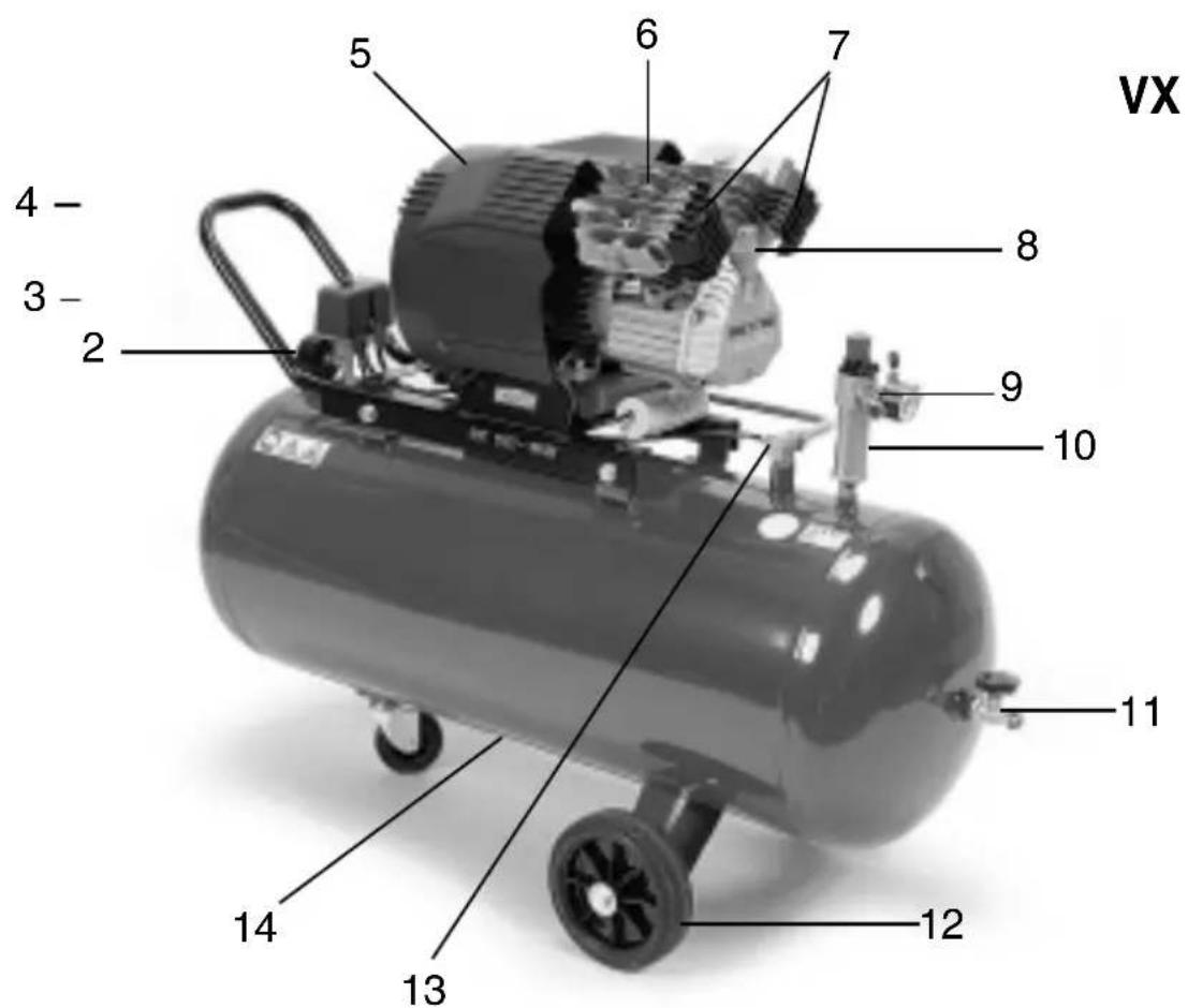
MOD. VX
- SERBATOIO / TANK / RESERVOIR / KESSEL / TANK / BEHOLDER / DEPÓSITO / DEPÓSITO / SÄILIÖ / TANK
- MANOMETRO / PRESSURE GAUCE / MANOMETRE / MANOMETER / MANOMETER / TRYKMÄLER / MANÓMETRO / MANÓMETRO / MANOMETRI / MANOMETER
- PRESSOSTATO / PRESSURE SWITCH / PRESSOSTAT / DRUCKWÄCHTER / DRUKREGELAAR / PRESSOSTAT / PRESOSTATO / BARÓSTATO / PAINEMITTARI / TYCKMÄTARE
- MANICO / HANDLE / POIGNEE / SCHLAUCH / HANDVAT / HANK / MANIJA / ASA / KAHVA / HANDTAG
- CARENATURA DI PROTEZIONE / GUARD / CARENAGE DE PROTECTION / SCHUTZVERKLEIDUNG / BESCHERMINGSSTROOMLIJNKAP / STRÖMLINIEBEKLÄEDNING / CARENADURA DE PROTECCIÓN / COBERTURA DE PROTECÇÃO / SUOJUS / SKYDDSBEKLÄDNAD
- GRUPPO COMPRESSORE / COMPRESSOR UNIT / GROUPE COMPRESSEUR / KOMPRESSORAGGREGAT / COMPRESSOR GROEP / KOMPRESSORENHEO / GRUPO COMPRESSOR / GRUPO COMPRESSOR / KOMPRESSORIYKSIKKÖ / KOMPRESSORGRUPP
-
FILTRI ARIA / AIR FILTER / FILTRE A AIR / LUFTFILTER / LUCHTFILTER / LUFTFILTER / FILTRO DE AIRE / FILTRO AR / ILMASUODATIN / LUFTFILTER
-
ASTA LIVELLO OLIO / OIL LEVEL STICK / TIGE DE NIVEAU D'HUILE / ÖLSTAB / STOK OLIENIVEAU / OLIEMÄLEPIND / VARILLA NIVEL DE ACEITE / VARETA NÍVELÓLEO / ÖLJYTASOTANKO / OLIEMÄTSTICKA
-
USCITA ARIA COMPRESSA RIDOTTA / REDUCED COMPRESSED AIR OUTLET / SORTIE RÉDUITE AIR COMPRIMÉ / REDUZIERTE DRUCKLUFTAUSGANG / UITGANG SAMENGEPERSTE LUCHT VERMINDERD / UDGANG FOR REDUCERET TRYKLUFT / SALIDA DEL AIRE COMPRIMIDO REDUCIDA / SAÍDA AR COMPRIMIDO REDUZIDA / PAINEILMAN VÄHENNETTY ULOSMENO / REDUCERAD TRYCKLUFTSUTGÅNG
-
RIDUTTORE DI PRESSIONE / PRESSURE REDUCER / REDUCTEUR DE PRESSION / DRUCKMINDERER / DRUKREDUCTIEMACHINE / TRYKBEGRÄNSER / REDUCTOR DE PRESIÓN / REDUTOR DE PRESSÃO / PAINEENVÄHENTÄJÄ / TYCKREDUCERARE
-
USCITA ARIA COMPRESSA DIRETTA / DIRECT COMPRESSED AIR OUTLET / SORTIE DIRECTE AIR COMPRIMÉ / DIREKTER DRUCKLUFTAUSGANG / UITGANG SAMENGEPERSTE LUCHT DIRECT / UDGANG FOR DIREKTE LUFTTRYK / SALIDA DEL AIRE COMPRIMIDO DIRECTA / SAÍDA AR COMPRIMIDO DIRECTA / PAINEILMAN SUORA ULOSMENO / DIREKT TRYCKLUFTSUTGÅNG
-
RUOTA / WHEEL / ROUE / RAD / WIEL / HJUL / RUEDA / RODA / PYÖRÄ / HJUL
-
VALVOLA DI NON RITORNO / CHECK VALVE / VANNE DE NON-RETOUR / RÜCKSCHLAGVENTIL / KLEP VOOR NIET TERUGKEER / KONTRAVENTIL / VÁLVULA DE ANTIRRETROCESO / VÁLVULA DE NÃO RETORNO / TAKAISKUVENTTIILI / VENTIL UTAN ÄTERGÅNG
-
SCARICO CONDENSA / CONDENSATE DRAIN / EVACUATION CONDENSATION / AUSLASS KONDENSWASSER / AFVOER CONDENSWATER / T∅MNING AF KONDENSVAND / DESAGÜE DEL CONDENSADO / PURGA DA CONDENSAÇÃO / KONDENSSIVEDEN TYHJENNYS / KONDENSVATTNETS AVLOPP
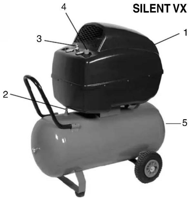
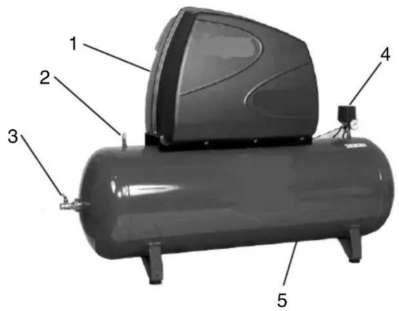
MOD. SILENT (AB e VX)
- CARENATURA DI PROTEZIONE / GUARD / CARENAGE DE PROTECTION / SCHUTZVERKLEIDUNG / BESCHERMINGSSTROOMLIJNKAP / STRÖMLINIEBEKLÄEDNING / CARENADURA DE PROTECCIÓN / COBERTURA DE PROTECCÃO / SUOJUS / SKYDDSBEKLÄDNAD
- VALVOLA DI SICUREZZA / SECURITY VALVE / VANNE DE SECURITE / SICHERHEITSVENTIL / VEILIGHEIDSKLEP / SIKKERHEDSVENTIL / VALVULA DE SEGURIDAD / VALVULA DE SEGURANCA / PAINEENALENNENNUSVENTTIIILI / SÄKERHETSVENTIL
- USCITA ARIA COMPRESSA DIRETTA / DIRECT COMPRESSED AIR OUTLET / SORTIE DIRECTE AIR COMPRIMÉ / DIREKTER DRUCKLUFTAUSGANG / UITGANG SAMENGEPERSTE LUCHT DIRECT / UDGANG FOR DIREKTE LUFTTRYK / SALIDA DEL AIRE COMPRIMIDO DIRECTA / SAÍDA AR COMPRIMIDO DIRECTA / PAINEILMAN SUORA ULOSMENO / DIREKT TRYCKLUFTSUTGÅNG
- PRESSOSTATO / PRESSURE SWITCH / PRESSOSTAT / DRUCKWÄCHTER / DRUKREGELAAR / PRESSOSTAT / PRESOSTATO / BARÓSTATO / PAINEMITTARI / TYCKMÄTARE
- SERBATOIO / TANK / RESERVOIR / KESSEL / TANK / BEHOLDER / DEPÓSITO / DEPÓSITO / SÄILIÖ / TANK
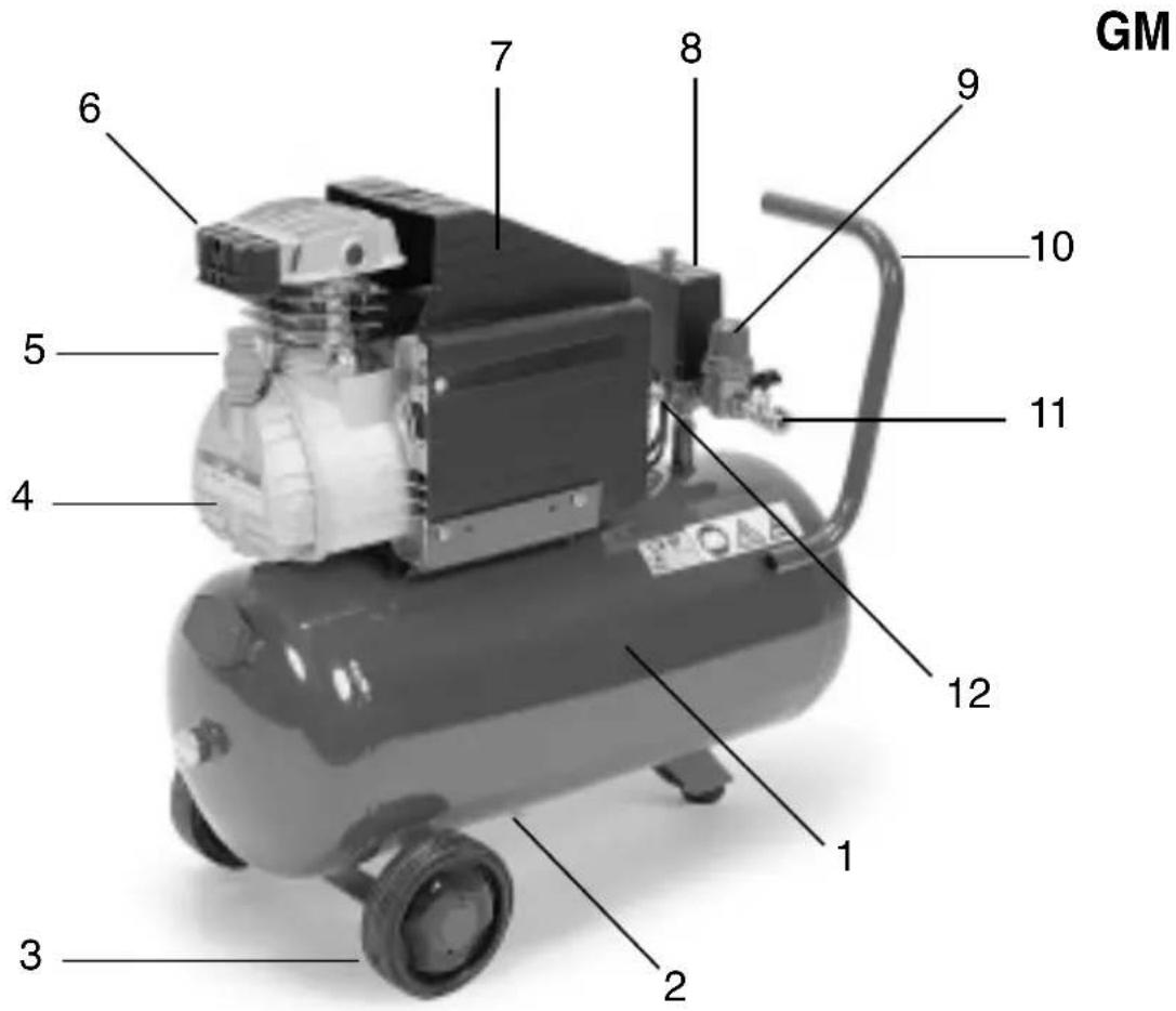
MOD. GM 203
- CARENATURA DI PROTEZIONE / GUARD / CARENAGE DE PROTECTION / SCHUTZVERKLEIDUNG / BESCHERMINGSSTROOMLIJNKAP / STRÖMLINIEBEKLÄEDNING / CARENADURA DE PROTECCIÓN / COBERTURA DE PROTECCÃO / SUOJUS / SKYDDSBEKLÄDNAD
- TAPPO SFIATO OLIO / BREATHER PLUG / BOUCHON DE PURGE / ENTLUFTUNGSSTOPFEN / VENTILPROP / TAPON DE PURGA / TAMPAO DE PURGA / ILMATULPPAAN / LUFTHAL
- MANICO / HANDLE / POIGNEE / SCHLAUCH / HANDVAT / HANK / MANIJA / ASA / KAHVA / HANDTAG
- PRESSOSTATO / PRESSURE SWITCH / PRESSOSTAT / DRUCKWÄCHTER / DRUKREGELAAR / PRESSOSTAT / PRESOSTATO / BARÓSTATO / PAINEMITTARI / TYCKMÄTARE
- RUOTA / WHEEL / ROUE / RAD / WIEL / HJUL / RUEDA / RODA / PYÖRÄ / HJUL
- SERBATOIO / TANK / RESERVOIR / KESSEL / TANK / BEHOLDER / DEPÓSITO / DEPÓSITO / SÄILIÖ / TANK
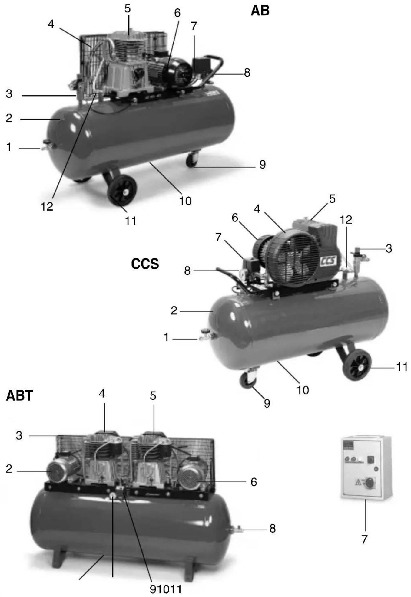
MOD. AB - MOD. CCS
- USCITA ARIA COMPRESSA DIRETTA / DIRECT COMPRESSED AIR OUTLET / SORTIE DIRECTE AIR COMPRIMÉ / DIREKTER DRUCKLUFTAUSGANG / UITGANG SAMENGEPERSTE LUCHT DIRECT / UDGANG FOR DIREKTE LUFTTRYK / SALIDA DEL AIRE COMPRIMIDO DIRECTA / SAÍDA AR COMPRIMIDO DIRECTA / PAINEILMAN SUORA ULOSMENO / DIREKT TRYCKLUFTSUTGÅNG
- SERBATOIO / TANK / RESERVOIR / KESSEL / TANK / BEHOLDER / DEPÓSITO / DEPÓSITO / SÄILIÖ / TANK
- RIDUTTORE DI PRESSIONE / PRESSURE REDUCER / REDUCTEUR DE PRESSION / DRUCKMINDERER / DRUKREDUCTIEMACHINE / TRYKBEGRÄNSER / REDUCTOR DE PRESIÓN / REDUTOR DE PRESSÃO / PAINEENVÄHENTÄJÄ / TYCKREDUCERARE
- PARACINGHIA / BELT-GUARD / PROTECTION COURROIE / RIEMENSCHUTZ / KETTINGBESCHERMER / BESKYTTELSESSKÆRM FOR REM / CUBRECORREA / PROTECÇÃO DA CORREIA / HIHNASUOJUS / REMSKYDD
- GRUPPO COMPRESSORE / COMPRESSOR UNIT / GROUPE COMPRESSEUR / KOMPRESSORAGGREGAT / COMPRESSOR GROEP / KOMPRESSORENHED / GRUPO COMPRESSOR / GRUPO COMPRESSOR / KOMPRESSORIYKSIKKÖ / KOMPRESSORGRUPP
- MOTORE ELETTRICO / ELECTRIC MOTOR / MOTEUR ÉLECTRIQUE / ELEKTROMOTOR / ELEKTRISCHE MOTOR / ELEKTRISK MOTOR / MOTOR ELÉCTRICO / MOTOR ELÉCTRICO / SÄHKÖMOOTTORI / ELMOTOR
- PRESSOSTATO / PRESSURE SWITCH / PRESSOSTAT / DRUCKWÄCHTER / DRUKREGELAAR / PRESSOSTAT / PRESOSTATO / BARÓSTATO / PAINEMITTARI / TYCKMÄTARE
- MANOMETRO / PRESSURE GAUCE / MANOMETRE / MANOMETER / MANOMETER / TRYKMÅLER / MANÓMETRO / MANÓMETRO / MANOMETRI / MANOMETER
- RUOTA PIVOTTANTE / PIVOT WHEEL / ROUE PIVOTANTE / SCHWENKRAD / DRAAIEND WIEL / HJULTAP / RUEDA PIVOTANTE / RODA GIRATÓRIA / KÄÄNTÖPYÖRÄ / ROTERANDE HJUL
- SCARICO CONDENSA / CONDENSATE DRAIN / EVACUATION CONDENSATION / AUSLASS KONDENSWASSER / AFVOER CONDENSWATER / TÖMNING AF KONDENSVAND / DESAGÜE DEL CONDENSADO / PURGA DA CONDENSAÇÃO / KONDENSSIVEDEN TYHJENNYS / KONDENSVATTNETS AVLOPP
- RUOTA / WHEEL / ROUE / RAD / WIEL / HJUL / RUEDA / RODA / PYÖRÄ / HJUL
- VALVOLA DI RITEGNO / CHECK VALVE / VANNE DE RETENNE / RÜCKSCHLAGVENTIL / TEGENHOUDKLEP / KONTRAVENTIL / VÁLVULA DE RETENCIÓN / VÁLVULA DE RETENÇÃO / TAKAISKUVENTTILI / STOPPVENTIL
MOD. ABT
- SERBATOIO / TANK / RESERVOIR / KESSEL / TANK / BEHOLDER / DEPÓSITO / DEPÓSITO / SÄILIÖ / TANK
- MOTORE ELETTRICO N. 1 / ELECTRIC MOTOR N. 1 / MOTEUR ÉLECTRIQUE N. 1 / ELEKTROMOTOR NR. 1 / ELEKTRISCHE MOTOR N. 1 / ELEKTRISK MOTOR NR. 1 / MOTOR ELÉCTRICO N. 1 / MOTOR ELÉCTRICO N° 1 / SÄHKÖMOOTTORI N: 1 / ELMOTOR NR. 1
- PARACINGHIA / BELT-GUARD / PROTECTION COURROIE / RIEMENSCHUTZ / KETTINGBESCHERMER / BESKYTTELSESSKÆRM FOR REM / CUBRECORREA / PROTECÇÃO DA CORREIA / HIHNASUOJUS / REMSKYDD
- GRUPPO COMPRESSORE N. 1 / COMPRESSOR UNIT N. 1 / GROUPE COMPRESSEUR N. 1 / KOMPRESSORAGGREGAT NR. 1 / COMPRESSOR GROEP N. 2 / KOMPRESSORENHEED NR. 1 / GRUPO COMPRESSOR N. 1 / GRUPO COMPRESSOR N° 1 / KOMPRESSORIYKSIKKÖ N: 1 / KOMPRESSORGRUPP NR. 1
- GRUPPO COMPRESSORE N. 2 / COMPRESSOR UNIT N. 2 / GROUPE COMPRESSEUR N. 2 / KOMPRESSORAGGREGAT NR. 2 / COMPRESSOR GROEP N. 2 / KOMPRESSORENHEED NR. 2 / GRUPO COMPRESSOR N. 2 / GRUPO COMPRESSOR N° 2 / KOMPRESSORIYKSIKKÖ N: 2 / KOMPRESSORGRUPP NR. 2
- MOTORE ELETTRICO N. 2 / ELECTRIC MOTOR N. 2 / MOTEUR ÉLECTRIQUE N. 2 / ELEKTROMOTOR NR. 2 / ELEKTRISCHE MOTOR N. 2 / ELEKTRISK MOTOR NR. 2 / MOTOR ELÉCTRICO N. 2 / MOTOR ELÉCTRICO N° 2 / SÄHKÖMOOTTORI N: 2 / ELMOTOR NR. 2
- CENTRALIANA AVVIAMENTO YD / STARTING CONTROL UNIT YD / BOÎTIER DE DÉMARRAGE Y? / STERNDREIECKANLASSER / CENTRALE OPSTARTEN UD / ELEKTRONISK BETJENINGSPANEL FOR START YD / CENTRAL DE PUESTA EN MARCHA YD / CAIXA DE ARRANQUE YD / KÄYNNISTYS VAIHDELAATIKKO YD / STARTCENTRAL YD
- USCITA ARIA COMPRESSA DIRETTA / DIRECT COMPRESSED AIR OUTLET / SORTIE DIRECTE AIR COMPRIMÉ / DIREKTER DRUCKLUFTAUSGANG / UITGANG SAMENGEPERSTE LUCHT DIRECT / UDGANG FOR DIREKTE LUFTTRYK / SALIDA DEL AIRE COMPRIMIDO DIRECTA / SAÍDA AR COMPRIMIDO DIRECTA / PAINEILMAN SUORA ULOSMENO / DIREKT TRYCKLUFTSUTGÅNG
- PRESSOSTATO / PRESSURE SWITCH / PRESSOSTAT / DRUCKWÄCHTER / DRUKREGELAAR / PRESSOSTAT / PRESOSTATO / BARÓSTATO / PAINEMITTARI / TYCKMÄTARE
- MANOMETRO / PRESSURE GAUCE / MANOMETRE / MANOMETER / MANOMETER / TRYKMÄLER / MANÓMETRO / MANÓMETRO / MANOMETRI / MANOMETER
- SCARICO CONDENSA / CONDENSATE DRAIN / EVACUATION CONDENSATION / AUSLASS KONDENSWASSER / AFVOER CONDENSWATER / TÖMNING AF KONDENSVAND / DESAGÜE DEL CONDENSADO / PURGA DA CONDENSAÇÃO / KONDENSSIVEDEN TYHJENNYS / KONDENSVATTNETS AVLOPP
FIAC Oil Synthesis....500
Olio sintetico
AGIP Sint 2000 Evolution - BP Visco 5000 - ESSO Ultron -
MOBIL Mobil 1 - NILS Dimension S - NUOVA STILMOIL
Arrow5W50)....400
Read and understand all of the operating instructions, safety precautions and warnings in the Instruction Manual before operating or maintaining this compressor.
Most accidents that result from compressor operation and maintenance are caused by the failure to observe basic safety rules or precautions. An accident can often be avoided by recognizing a potentially hazardous situation before it occurs, and by observing appropriate safety procedures.
Basic safety precautions are outlined in the "SAFETY" section of this Instruction Manual nad in the sections which contain the operation and maintenance instructions.
Hazards that must be avoided to prevent bodily injury or machine damage are identified by WARNINGS on the compressor and in this Instruction Manual.
Never use this compressor in a manner that has not been specifically recommended by manufacturer, unless you first confirm that the planned use will be safe for you and others.
MEANINGS OF SIGNAL WORDS
WARNING: indicates a potentially hazardous situations which, if ignored, could result in serious personal injury.
CAUTION: indicates a hazardous situations which, if ignored, couls result moderate personal injury, or could cause machine damage.
NOTE: emphasizes essential information
SAFETY
IMPORTANT SAFETY INSTRUCTIONS FOR USE
OF THE COMPRESSOR.
WARNING:
DEATH OR SERIOUS BODILY INJURY COULD RESULT FROM IMPROPER OR UNSAFE USE OF COMPRESSOR. TO AVOID THESE RISKS, FOLLOW THESE BASIC SAFETY INSTRUCTIONS.
READ ALL INSTRUCTIONS
Never place your hands, fingers or other body parts near the compressor's moving parts.
2. NEVER OPERATE WITHOUT ALL GUARDS IN PLACE
Never operate this compressor without all guards or safety features in place and in proper working order. If maintenance or servicing requires the removal of a guard or safety features, be sure to replace the guards or safety feature before resuming operation of the compressor.
3. ALWAYS WEAR EYE PROTECTION
Always wear safety goggles or equivalent eye protection. Compressed air must never be aimed at anyone or any part of the body.
4. PROTECT YOURSELF AGAINST ELECTRIC SHOCK
Prevent body contact with grounded surfaces such as pipes, radiators, ranges and refrigeration enclosures. Never operate the compressor in damp or wet locations.
5. DISCONNECT THE COMPRESSOR
Always disconnect the compressor from the power source and remove the compressed air from the air tank before servicing, inspecting, maintaining, cleaning, replacing or checking any parts.
6. AVOID UNINTENTIONAL STARTING
Do not carry the compressor while it is connected to its power source or when the air tank is filled with compressed air. Be sure the knob of the pressure switch in the "OFF" position before connecting the
compressor to its power source.
7. STORE COMPRESSOR PROPERLY
When not in use, the compressor should be stored in dry place. Keep out of reach of children. Lock-out the storage area.
8. KEEP WORK AREA CLEAN
Cluttered areas invite injurues. Clear all work areas of unnecessary tools, debris, furniture etc...
9. KEEP CHILDREN AWAY
Do not let visitors contact compressor extension cord. Alla visitors should be kept safely away from work area.
10. DRESS PROPERLY
Do not wear loose clothing or jewerly. They can be caught in moving parts. Wear protective hair covering to contain long hair.
11. DON'T ABUSE CORD
Never yank it to disconnect from receptable. Keep cord from heat, oil and sharp edges.
12. MAINTAIN COMPRESSOR WITH CARE
Follow instructions for lubricating. Inspect cords periodically and if damaged, have repaired by authorized service facility. Inspect extension cords periodically and replace if damaged.
13. OUTDOOR USE EXTENSION CORDS
When compressor in used outdoors, use only extension cords intended for use outdoors and so marked.
14. STAY ALERT
Watch what you are doing. Use common sense. Do not operate compressor when you are tired.
Compressor should never be used by you if you are under the influence of alcohol, drugs or medication that makes you drowsy.
15. CHECK DAMAGED PARTS AND AIR LEAK
Before further use of the compressor, a guard or other part is damaged should be carefully checked to determine that it will operate properly and perform its intended function.
Check for alignment of moving parts, binding of moving parts, breakage of parts, mounting, air leak, and any other conditions that may affect its operation.
A guard or other part that is damaged should be properly repaired or replaced by an authorized service center unless otherwise indicated elsewhere in this Instruction Manual. Have defective pressure switches replaced by authorized service center. Do not use compressor if switch does not turn it on and off.
16. HANDLE COMPRESSOR CORRECTLY
Operate the compressor according to the instructions provided herein. Never allow the compressor to be operated by children, individuals unfamiliar with its operation or unauthorized personnel.
17. KEEP ALL SCREWS, BOLTS AND COVERS TIGHTLY IN PLACE Keep all screws, bolts, and plates tightly mounted.
Check their conditions periodically.
18. KEEP MOTOR AIR VENT CLEAN
The motor air vent must be kept clean so that air can freely flow at all times. Check for dust build-up frequently.
19. OPERATE COMPRESSOR AT THE RATED VOLTAGE
Operate the compressor at voltages specified on their nameplates. If using the compressor at a higher voltage than the rated voltage, it will result in abnormally fast motor revolution and may damage the unit and burn out the motor.
20. NEVER USE A COMPRESSOR WHICH IS DEFECTIVE OR OPERATING ABNORMALLY
If the compressor appears to be operating unusually, making strange noises, or otherwise appears defective, stop using it immediately and arrange for repairs by a authorized service center.
21. DO NOT WIPE PLASTIC PARTS WITH SOLVENT
Solvents such as gasoline, thinner, benzine, carbon tetrachloride, and alcohol may damage and crack plastic parts. Do not wipe them with such solvents. Wipe plastic parts with a soft cloth lightly
dampened with soapy water and dry thoroughly.
22. USE ONLY GENUINE REPLACEMENT PARTS
Replacement parts not original may void your warranty and can lead to malfunction and resulting injuries. Genuine parts are available from your dealer.
23. DO NOT MODIFY THE COMPRESSOR
Do not modify the compressor. Always contact the authorized service center any repairs. Unauthorized modification may not only impair the compressor performance but may also result in accident or injury to repair personnel who do not have the required knowledge and technical expertise to perform the repair operations correctly.
24. TURN OFF THE PRESSURE SWITCH WHEN THE COMPRESSOR IS NOT USED
When the compressor is not used, turn the knob of the pressure switch OFF, disconnect it from the power source and open the drain cock to discharge the compressed air from the air tank.
To reduce the risk of burns, do not touch tubes, heads, cylinder and motors.
26. DO NOT DIRECT AIR STREAM AT BODY
Risk of injury, do not direct air stream at persons or animals.
27. DRAIN TANK
Drain tank daily or after 4 hours of use.
Open drain fitting and tilt compressor to empty accumulated water.
28. DO NOT STOP COMPRESSOR BY PULLING OUT THE PLUG
Use the "AUTO/OFF" knob of pressure switch.
29. USE ONLY RECOMMENDED AIR HANDLING PARTS ACCEPTABLE FOR PRESSURE NOT LESS THAN 125 PSI (8.6 BAR)
Risk of bursting. Use only recommended air handling parts acceptable for pressures not less than 125 psi (8.6 bar).
REPLACEMENT PARTS
When servicing use only identical replacement parts.
Repairs should be conducted only by authorized service center.
SAFETY - continued
GROUNDING INSTRUCTIONS
This compressor should be grounded while in use to protect the operator from electric shock. The compressor is equipped with a three-conductor cord and three-prong grounding type plug to fit the proper grounding type receptacle.
The green (or green and yellow) conductor in the cord is the grounding wire. Never connect the green (or green and yellow) wire to a live terminal. If your units is for use on less than 150 volts, it has a plug that looks like that shown in sketch (A) in figure on the right. An adapter, see sketches (B) and (C), is available for connecting sketch (A) type plugs to two-prong receptacles. The green-colored rigid ear, lug, or the like extending from the adapter must be connected to a permanent ground, such as a properly grounded outlet box.
NOTE: the grounding adaptor, sketch (C), is prohibited in Canada by Canadian Electrical Code Part.1. Therefore, the instructions for its use are not applicable in Canada.
EXTENSION CORD
Use only three-extension cords that have three-prong grounding type plugs and three-pole receptables that accept the compressor's plug. Replace or repair damaged cord. Make sure your extension cord is in good condition. When using an extension cord, be sure to use one heavy enough to carry the current your product will draw. An undersized cord will cause a drop in line voltage resulting in loss of power and overheating. Table shows the correct size to use depending on cord length and name plate ampere rating. If in doubt, use the next heavier gage. The smaller the gage number, the heavier the cord.
Tab.1 SECTION VALID FOR A MAX LENGTH OF 20 mt single-phase CV kW 220/230V 110/120V
| mm^2 | mm^2 | |
| 0.75 - 1 0.65 - 0.7 1.5 2.5 | ||
| 1.5 1.1 2.5 4 | ||
| 2 1.5 2.5 4 - 6 | ||
| 2.5 - 3 1.8 - 2.2 | 4 | / |
The diameter of the extension cable of the 3-phase compressors must be in proportion to its length: see table (tab 2)
Tab. 2 SECTION VALID FOR A MAX LENGTH OF 20 mt three-phase CV kW 220/230V 380/400V
| mm^2 | mm^2 | ||
| 2-3-4 | 1.5-2.2-3 | 2.5 1.5 | |
| 5.5 | 4 | 4 | 2 |
| 7.5 | 5.5 6 | 2.5 | |
| 10 | 7.5 | 10 4 |
WARNING
Avoid electrical shock hazard. Never use this compressor with a damaged or frayed electrical cord or extension cord. Inspect all electrical cords regularly. Never use in near water or in any environment where electric shock is possible
SAVE THESE INSTRUCTION AND
MAKE THEM AVAILABLE TO OTHER USERS OF THIS TOOL!
NOTE: The information contained in this Instruction Manual is designed to assist you in the safe operation and maintenance of the compressor. Some illustrations in this Instruction Manual may show details or attachments that differ from those on your own compressor.
INSTALLATION
Remove the compressor from its packing (fig.1), makes sure it is in perfect condition, checking if it was damaged during transport, and carry out the following operations. Fit the wheels and rubber tab on the tanks on which they are not already fitted, observing the instructions in fig.2. In case of inflatable wheels, the maximum inflation pressure must be of 1,6 bar (24 psi). Position the compressor on a flat surface or with a maximum permissible inclination of 10^ (fig. 3), in a well aired place, protected against atmospheric agents and not in a place subject to explosion hazard. If the surface is inclined and smooth, check if the compressor moves while in operation – if it does, secure the wheels with two wedges. If the surface is a bracket or a shelf top, make sure it cannot fall, securing it in a suitable way. To ensure good ventilation and efficient cooling, the compressor's belt guard must be at least 100 cm from any wall (fig. 4). Compressors fitted on the tank, with fixed feet, should not be rigidly secured to the ground. In this case, we advise you to fit 4 anti-vibration supports.
USE INSTRUCTIONS
- Take care to transport the compressor correctly, do not overturn it or lift it with hooks or ropes (fig. 5 - 6)
- Replace the plastic plug on the guard cover (fig. 7 - 8) with the oil level stick (fig. 9) or with the relevant breather plug (fig. 10), supplied with the instructions booklet. Check oil level, consulting the reference marks on the stick (fig. 9) or the oil level inspection window (fig. 11).
ELECTRICAL CONNECTION
Single-phase compressors are supplied with an electrical cable and a two-pole + earth plug. The compressor must be connected to a grounded power socket (fig.12).
Three-phase compressors (L1+L2+L3+PE) must be installed by a specialised technician. Three-phase compressors are supplied without a plug. Connect a plug, with screw-on grommet and securing collar (fig.13), to the cable, consulting the table below.
HP kW Power supply volt/ph Plug model
$$ 2 - 3 - 4 \quad 1. 5 - 2. 2 - 3 \quad 2 2 0 / 3 8 0 / 3 $$
$$ 2 3 0 / 4 0 0 / 3 \quad 1 6 A \quad 3 \text { pole } + \text { ground } $$
$$ 5. 5 - 7. 5 - 1 0 4 - 5. 5 - 7. 5 2 2 0 / 3 8 0 / 3 $$
$$ 2 3 0 / 4 0 0 / 3 \quad 3 2 A \quad 3 \text { pole } + \text { ground } $$
NOTE: Compressors installed on the 500 lt tank, with capacity of HP7.5/55 kW and HP10/7.5 kW can be supplied a star/triangle starting control unit, whereas the TANDEM (n. 2 pumping elements on the same tank) are supplied with a timed control unit for staggered starting of the two pumping elements.
Installation instructions:
- Secure the control unit box on a wall or on a fixed support, and provide it with a power cable with plug, of a diameter in proportion to its length.
– Any damage caused by incorrect connections of the power line to the mains, automatically excludes warranty of electrical parts. To avoid connection errors, we advise you to contact a specialised technician.
IMPORTANT:
Never use the ground socket instead of the neutral wire. The ground connection must be made to meet safety standards(EN 60204).
The plug of the power cable must not be used as a switch, but must be fitted in a power socket controlled by a suitable differential switch (thermal-breaker).
STARTING
Check that the mains power matches that indicated on the electrical data-plate (fig.14) – the permissible tolerance range is +/-5%. When first starting compressors operating on 3-phase voltage, check the rotation direction of the cooling fan by comparing it with the direction of the arrow on the belt guard or on the protective housing. In the SILENT compressor, check if the air flows is in the direction illustrated in fig.21A. Turn or press into position "0" (according to the type of pressure switch fitted on the appliance) the knob located on the upper section (fig. 15).
Fit the plug in the power socket (fig. 12 - 13) and start the compressor, turning the pressure switch knob into position "I". The compressor is fully automatic, and is controlled by the pressure switch which stops it when tank pressure reaches maximum value and restarts it when it falls to minimum value. The pressure difference between maximum and minimum values is usually about 2 bar (29 psi).
E.g.: the compressor stops when it reaches 8 bar (116 psi – maximum operating pressure) and restarts automatically when the pressure inside the tank drops to 6 bar (87 psi).
After connecting the compressor to the power line, load it to maximum pressure and check exactly how the machine is operating.
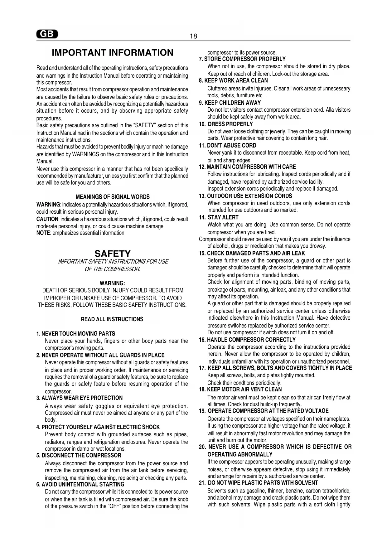
COMPRESSORS WITH ⚠ STARTING
CONTROL UNIT (fig. 16)
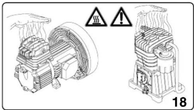
Fit the plug in the power socket (fig. 13) and turn the pressure switch to position "I" (ON) (fig. 17). Turn the master power switch "A" on the control unit to position I - power On is signalled by white indicator-light "E" going on. Turn switch "B" to position 1 to start the compressor. If the solenoid-valve indicator-light "D" and the motor (C) indicator-light (C) go on in that order, this means the machine is operating perfectly (fig. 18).
TANDEM COMPRESSORS WITH TIMED CONTROL UNIT (fig. 17)
Fit the plug in the power socket (fig. 13) and turn the pressure switch to position "I" (ON). Turn the master power switch "A" on the control unit to position I – power On is signalled by white indicator-light "E" going on.
Turn switch "B" to start the compressor.
Pos. 1 pumping element n. 1 only is operating
Pos. 2 pumping element n. 2 only is operating
Pos. 3 both pumping elements are operating simultaneously, at staggered starting times.
The compressor is fully automatic, and is controlled by the pressure switch which stops it when tank pressure reaches maximum value and restarts it when it falls to minimum value.
NOTE: The head/cylinder/delivery tube unit can reach
high temperatures. Take care when working near these parts, and do not touch them to avoid possible burns (fig. 18 - 19).
IMPORTANT
The electro-compressors must be connected to a power socket protected by a suitable differential switch (thermal-breaker). The motor of GM-TR compressors is equipped with an automatic thermal breaker located inside the winding – this stops the compressor when motor temperature reaches excessively high values.
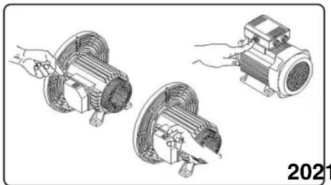
If the breaker is tripped, the compressors restarts automatically after 10 to 15 minutes. The motors of compressor models VX are supplied with a manually resetting automatic amperometric thermal-breaker, located outside the terminal board cover.
When the breaker is tripped, wait for a few minutes and then reset the breaker manually (fig. 20).
The motors of the AB series compressors are supplied with a manually resetting amperometric thermal-breaker, located on the terminal board cover. When the breaker is tripped, wait for a few minutes and then reset the breaker manually (fig. 20).
The safety device is automatic in three-phase and silent compressors.
When the thermal-breaker is tripped, the pressure switch is released to "0" (OFF) position.
Wait for a few minutes and return the pressure switch to "I" (ON) position (with the exception of models: AB 100/245-335 Three-phase - AB 150/245-335 Three-phase - AB 200/245-335 Three-phase). For compressors supplied with a control unit, the thermal-breaker is installed inside the control unit. When the thermal-breaker is tripped, observe the following procedure (fig. 22):
- Turn the switches on the control unit cover to position "0", open the cover and press push-button 1 of the thermal-breaker. Close the cover of the control unit and restart the compressor, observing the operations described in the paragraph "Starting compressors with control unit".
The same instructions apply to compressors powered at 60 Hz.
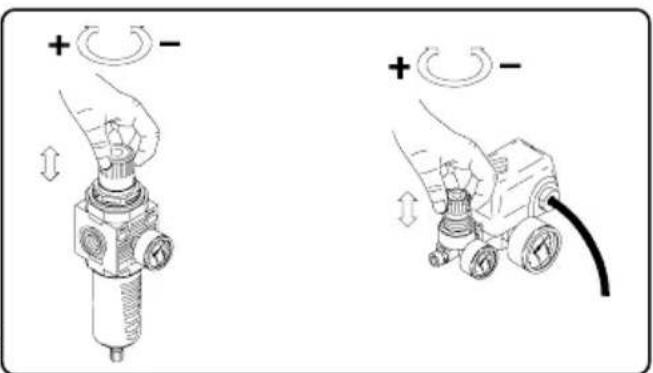
ADJUSTING OPERATING PRESSURE (fig. 23)
You do not have to use the maximum operating pressure at all times. On the contrary, the pneumatic tool being used often requires less pressure. On compressors supplied with a pressure reducer, operating pressure must be correctly adjusted.
Release the pressure reducer knob by pulling it up, adjust pressure to the required value by turning the knob clockwise to increase pressure and anti-clockwise to reduce it. When you have obtained optimum pressure, lock the knob by pressing it downward (fig. 23). For pressure reducers equipped without a pressure gauge, the set pressure can be seen on the graduated scale located on the reducer body.
On pressure reducers equipped with a pressure gauge, pressure can be seen on the gauge itself.
WARNING: Some pressure regulators do not have "push to lock", therefore simply turn the knob to adjust the pressure.
MAINTENANCE
Before attempting any maintenance jobs on the compressor, make sure of the following:
- Master power switch in position "0".
- Pressure switch and the control unit switches all off, in position "0".
- No pressure in the air tank.
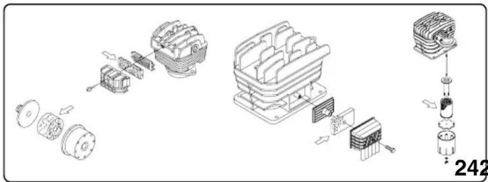
Every 50 hours of duty: we advise you to dismantle the suction filter and clean the filtering element by blowing compressed air on it (fig. 24).
You are recommended to replace the filter element at least once if the compressor operates in a clean environment, but more frequently if in a dusty environment.
In the "red-head" models (fig. 25) (TR200 – TR255), the suction filter is located internally under the conveying cover (read-head). Unscrew the three cover securing screws, remove the cover from the guard joint, remove the filter from its seat, and begin cleaning, blowing compressed air in opposite to normal flow direction.
In the Silent model, the filtering element can be replaced by taking off the soundproofing cabinet and proceeding in the same way as for the AB models (fig.29A).
The compressor generates condensate water which accumulates in the tank.
The condensate in the tank must be drained at least once a week, by opening the drain tap (fig. 26) under the tank.
Take care if there is compressed air inside the cylinder, and water could flow out with considerable force. Recommended pressure: 1 - 2 bar max.
Condensate of compressors that are oil lubricated must not be drained into the sewer or dispersed in the environment as it contains oil.
OIL CHANGES – TOPPING UP WITH OIL
The compressor is filled with synthetic oil "FIAC Oil Synthesis".
We recommend a full change of oil in the pumping element within the first 100 hours of duty.
The soundproofing cabinet is to be taken off first in the Silent model (fig.29A).
Unscrew the oil drain plug on the housing cover, allow all the oil to flow out, and re-screw the plug (fig. 27 - 28).
Pour oil into the upper hole of the housing cover (fig. 29 - 30) until it reaches the level indicated on the stick (fig. 9) or indicator (fig. 11)
Pour oil into the upper hole of the head (fig. 30) in belt assisted units designed for topping up in that area.
For the GM203 series, take the cap off and pour in 85 grams of oil directly from the bottle (see fig. 30a).
Once a week: check oil level of the pumping element (fig. 11) and see if it needs topping up.
For operation at ambient temperature in the range -5^ to +40^ , use synthetic oil. The advantage of this oil is that it does not lose its characteristics either in winter or summer.
Do not drain used oil into the sewer or dispose of it in the environment.
OBSERVE THIS TABLE FOR OIL CHANGES
TYPE OF OIL HOURS OF DUTY
FIAC Oil Synthesis....500
Synthetic oil:
AGIP Sint 2000 Evolution - BP Visco 5000 - ESSO Ultron -
MOBIL Mobil 1 - NILS Dimension S - NUOVA STILMOIL
Arrow5W50....400
Other types of oil: mineral multigrade
SAE 15 W40....100
WHAT TO DO IF SMALL MALFUNCTIONS OCCUR
Loss of air in valve under pressure switch
This trouble depends on poor tightness of the check valve - take the following action (fig. 31):
– Discharge all pressure from the tank
- Unscrew the hexagon-head of the valve (A)
- Carefully clean both the rubber disk (B) and its seat.
- Refit all parts accurately.
Air losses
These can be caused by poor tightness of a union – check all unions, wetting them with soapy water.
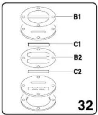
Compressor turns but does not load
Coaxial compressors: (fig. 32)
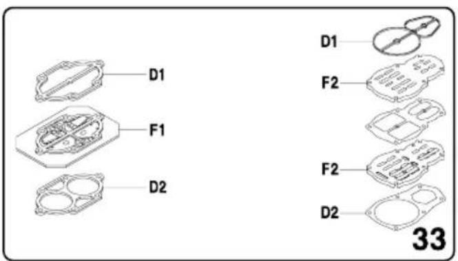
- this may be due to failure of the valves (C1 – C2) or of a seal (B1 – B2): replace the damaged part. Pulley drive compressors: (fig. 33)
- this may be due to failure of the valves F1 and F2 or of a seal (D1 – D2): replace the damaged part.
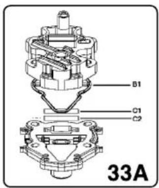
GM 203 compressors:
This may be due to the breakage of the valves (C1 - C2) or of the gasket (B1). Replace the damaged part (fig. 16A).
- Check if there is too much condensate water inside the tank.
Compressor no starting
If the compressor has trouble starting, check the following :
- Does mains power match that of the data-plate? (fig. 14)
- Are power cable extensions of adequate diameter or length?
- Is the work environment too cold? (under 0°C)
- For series VX/AB: was the thermal-breaker tripped? (fig. 20); in the silent series (fig. 21)
- Is there oil in the housing to ensure lubrication? (fig. 11)
- Is power supplied to the electrical line? (sockets well connected, thermal-breaker, fuses in good condition).
Compressor not stopping
- If the compressor does not stop when maximum pressure is reached, the tank safety valve comes into operation. To repair the valve, contact your nearest service centre.
IMPORTANT
- Do not on any account unscrew any connection while the tank is pressurised – always check if the tank is pressure free.
- Do not drill holes, weld or purposely deform the compressed air tank.
-
Do not do any jobs on the compressor unless you have disconnected the power plug.
-
Temperature in operating ambient: 0°C +35°C.
- Do not aim jets of water or inflammable liquids on the compressor.
- Do not place inflammable objects near the compressor.
- During down-times, turn the pressure switch to position "0" (OFF).
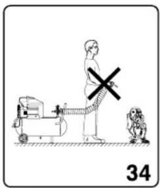
- Never aim the air jet at people or animals (fig. 34)
- Do not transport the compressor while the tank is pressurised.
- Be careful with regard to some parts of the compressor such as the head and delivery tubes, as they can reach high temperatures. Do not touch these parts to avoid burns.(fig. 18 - 19)
- Transport the compressor, lifting or pulling it with the appropriate grips or handles (fig. 4 - 6)
- Keep children and animals well away from the machine operating area.
- If using the compressor for painting:
a) Do not work in closed environments or near to naked flames
b) Make sure there is adequate exchange of air at the place of work
c) Protect your nose and mouth with an appropriate mask. (fig. 35)
- If the electrical cable or plug are damaged, do not use the compressor and contact an authorised service centre to replace the faulty element with an original spare part.
- If the compressor is located on a shelf or on a top above floor height, it must be secured to prevent it falling while in operation.
- Do not put objects or your hands inside the protective grilles to avoid injury to yourself or damaging the compressor. (fig. 36)
- Do not use the compressor as a blunt object toward things or animals, to avoid serious damage.
- When you have finished using the compressor, always remove the plug from the power socket.
ELECTRO-COMPRESSOR MODELS GM - TR
Maximum operating pressure 8.5 bar
Minimum operating pressure 8 bar
ELECTRO-COMPRESSOR MODELS VX
Maximum operating pressure 10.5 bar
Minimum operating pressure 10 bar
ELECTRO-COMPRESSOR MODELS AB
Maximum operating pressure 10.5 bar
Minimum operating pressure 10 bar
N.B. Two-stage compressors can be supplied on request for use up to 14 bar. In this case:
Maximum operating pressure 14.75 bar
Minimum operating pressure 14 bar
NOTE: The Silent model consists of the AB model completed with a soundproofing cabinet. The technical data and the instructions of this manual for the AB models also apply to the derived Silent models.
For the European market, the compressor tanks are manufactured to meet Directive CE2009/105
For the European market, the compressors are manufactured to meet Directive CE2006/42.
Acoustic pressure measured free-field at a distance of 1m: ±3dB(A) at maximum operating pressure. (tab. 3)
| GM VX | |||||
| HP/kW | RPM | dB(A) | HP/kW | RPM | dB(A) |
| 0.65/0.5 | 1450 | 73 | 1.5/1.1 | 1450 | 75 |
| 0.65/0.5 | 2800 | 75 | 2/1.5 | 1700-1450 | 75 |
| 0.75/0.65 | 1700-1450 | 73 | 2.5/1.8 | 14050 | 75.5 |
| 1.5/1.1 | 3400-2850 | 75 | 3/2.2 | 2850 | |
| 2/1.5 | 2850 | 79 | / | / | |
| 2.5/1.8 | 2850 | 82 | |||
| TR | ||
| HP/kW | RPM dB(A) | |
| 1.5/1.1 | 1700-2800 | 76 |
| 2/1.5 | 2800 | 80 |
| AB | ||
| Mod. | HP/kW dB(A) | |
| CCS | 2 - 1.5 | 77 |
| AB 245 | 2 - 1.5 | 78 |
| AB 335 | 3 - 2.25 | 80 |
| AB 410 | 3 - 2.25 | 80 |
| AB 510 | 4 - 3 | 85 |
| AB 480 | 4 - 3 | 81 |
| AB 530 | 4 - 3 | 82 |
| AB 550 | 5.5 - 4.1 | 83 |
| AB 671 | 5.5 - 4.1 | 84 |
| AB 851 | 7.5 - 5.5 | 83 |
| AB 1000 | 10 - 7.5 | 88 |
The level of acoustic pressure can increase from 1 to 0 dB (A) according to the place in which the compressor is installed.
The electric compressors on wheels with power greater then or equal to 3-Hp are intended for indoor use. HINTS FOR EFFICIENT OPERATION - For efficient operation of the machine at full continuing load and at
HINTS FOR EFFICIENT OPERATION -For efficient operation of the machine at full continuing load and at maximum operating pressure, make sure the temperature of the work environment indoors does not exceed -25°C. -We advise you to use the compressor at 70% maximum duty per hour at full load as this ensures efficient operation of the product long-term. STORING THE PACKED AND UNPACKED COMPRESSOR
For the whole time that the compressor is not used before unpacking it, storing THE PACKED AND UNPACKED-COMPRESSOR and for the whole time that the compressor is not used before unpacking it, store while a dry place at a temperature between 5°C and 45°C and sheltered away from weather. For the whole time that the compressor is not used after unpacking it, while waiting to start it up or due to production stoppages, place sheets over it to protect it from dust, which may settle on the components. The oil is to be replaced and the operational efficiency of the compressor is to be checked if it is not used for long periods.
Make sure you always use pneumatic tubes for compressed air with maximum pressure (PNEUMATIC CONNECTIONS) for the compressor. Make sure you always use pneumatic tubes for compressed air with maximum pressure characteristics that are adequate for the compressor. Do not attempt to repair tubes if faulty.
WE RESERVE THE RIGHT TO MAKE ANY MODIFICATIONS
WITHOUT RESERVE OTHER RIGHTS TO MAKE CONSARY.
MODIFICATIONS WITHOUT PRIOR NOTICE WHENEVER
NECESSARY.
INFORMATIONS IMPORTANTES
FIAC Oil Synthesis....500
Huile synthétique
AGIP Sint 2000 Evolution - BP Visco 5000 - ESSO Ultron
MOBIL Mobil 1 - NILS Dimension S - NUOVA STILMOIL
Arrow5W50....400
FIAC Oil Synthesis....500
Synthetiköl
AGIP Sint 2000 Evolution - BP Visco 5000 - ESSO Ultron -
MOBIL Mobil 1 - NILS Dimension S - NUOVA STILMOIL
Arrow5W50)....400
FIAC Oil Synthesis....500
Synthetische olie
AGIP Sint 2000 Evolution - BP Visco 5000 - ESSO Ultron -
MOBIL Mobil 1 - NILS Dimension S - NUOVA STILMOIL
Arrow5W50)....400
Andere types van minerale multigraden olie
SAE 15 W40....100
HOE TUSSENKOMEN BIJ KLEINE AFWIJKINGEN
- AFBRYD KOMPRESSOREN FRA ELNETTET
FIAC Oil Synthesis....500
Syntetisk olie
AGIP Sint 2000 Evolution - BP Visco 5000 - ESSO Ultron -
MOBIL Mobil 1 - NILS Dimension S - NUOVA STILMOIL
Arrow5W50)....400
Andre typer for mineralsk multigrade olie
SAE 15 W40 ....100
UDBEDRING VED MINDRE FEJLFUNKTIONER
FIAC Oil Synthesis....500
Aceite sintético
AGIP Sint 2000 Evolution - BP Visco 5000 - ESSO Ultron -
MOBIL Mobil 1 - NILS Dimension S - NUOVA STILMOIL
Arrow5W50)....400
FIAC Oil Synthesis....500
Óleo sintético
AGIP Sint 2000 Evolution - BP Visco 5000 - ESSO Ultron -
MOBIL Mobil 1 - NILS Dimension S - NUOVA STILMOIL
Arrow5W50)....400
Outros tipos de óleo multigrade mineral
SAE 15 W40 ....100
COMO INTERVIR EM PEQUENAS ANOMALIAS
FIAC Oil Synthesis....500
HYÖDYLLISIÄ NEUVOJA HYVÄLLE TOIMINNALLE
OBS: understryker viktig information.
SÄKERHET
VIKTIGA INSTRUKTIONER FÖR ETT SÄKERT BRUK AV KOMPRESSORN.
FIAC Oil Synthesis....500
Syntetisk olja
AGIP Sint 2000 Evolution - BP Visco 5000 - ESSO Ultron -
MOBIL Mobil 1 - NILS Dimension S - NUOVA STILMOIL
Arrow5W50)....400
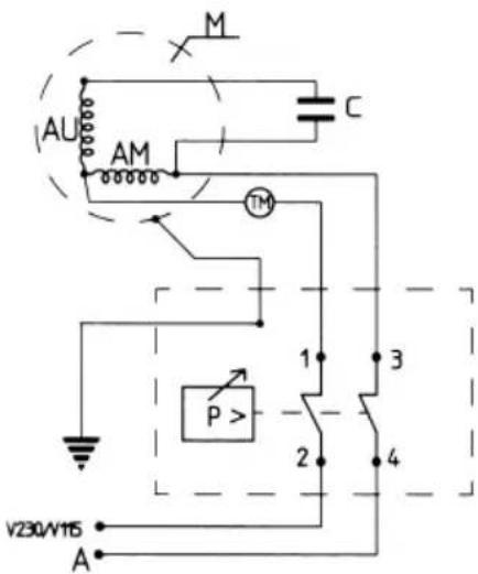
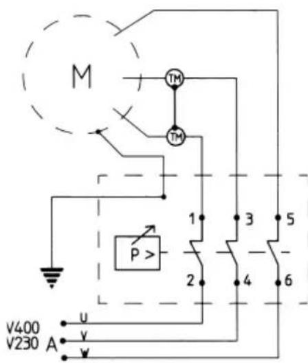
1-2-3-4-5-6 = WIRE CONNECTION TERMINALS
C = CONDENSER
M=MOTOR
AU = AUXILIARY WINDING
AM = STARTING WINDING

Alimentation
P = Pressostat
TM = MANUEL AMPERESIKRING
1-2-3-4-5-6 = KLEMMER TIL TILSLUTNING AF LEDNINGER
C = KONDENSATOR
M=MOTOR
AU = SEKUNDAERVIKLING

AM = STARTVIKLING

ALIMENTACIÓN
P = PRESOSTATO
TRIFASEV220/60/3
V230/50/3
THREE/PHASEV400/50/3
V380/50/3
V380/60/3
WARRANTY: The electro-compressors are warranted for 12 months as from duly documented date of sale.
This warranty is granted only to clients who are up to date with their payments.
The compressor is warranted for normal operational duty of 8 hours per day in a suitable place.
The compressor must be expertly installed. In the event of trouble caused by manufacturing faults occurring during the warranty period, the manufacturer shall replace free of charge parts recognised as faulty.
Travelling and labour costs shall be, in any event, charged to the client.
DEALER'S RUBBER STAMP

The following are excluded from the warranty: damage caused by poor maintenance, negligence and use under unsuitable conditions.
The guarantee does not cover motors and all other electrical parts as well as parts subject to wear.
DELIVERY DATE
MODEL