USER MANUAL VC520 Pro2 AVer
VC520 Pro2 Conference Camera
Quick Start Guide | 安装指南
安装指南|取叢説明書
哪种がい드!Mode d'emploi
Manual de instrucciones | KpaTkoe pyKOBODCTBO
English 1
繁體中文. 10
简体中文 20
日本語 29
HahK 38
Francais 47
Espanol 57
Pycckn 67
Package Contents
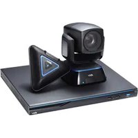
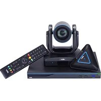
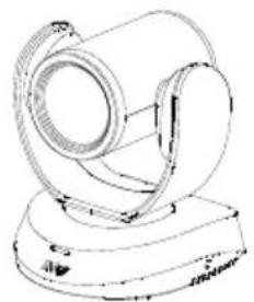
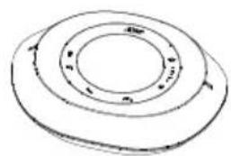
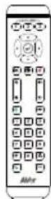
Camera Unit Speakerphone Unit Remote Control
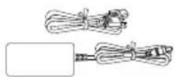
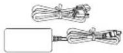
Power Adapter & Power Cord*

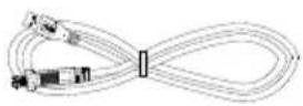
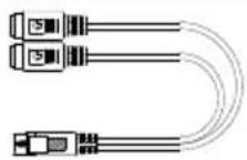
USB 2.0 Type-B to Type-A Cable (5m)
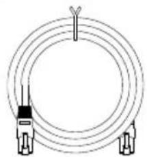
Speakerphone Cable (10m)
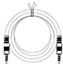
3.5 mm Audio Cable (0.9m)
L-Mount Brackets
Screws for Mount
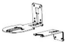
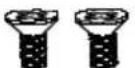
M4 x8mm (x2)
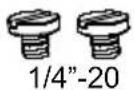
L=7.5mm (x2)
Drilling Paper QR Code Card
- The power cord will vary depending on the standard power outlet of the country where it is sold.
Optional Accessory
Mini DIN9 to Mini DIN8 RS232 Adapter Cable
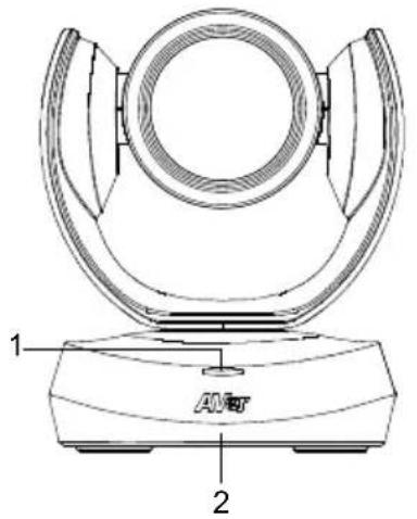
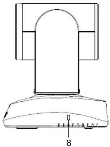
Overview
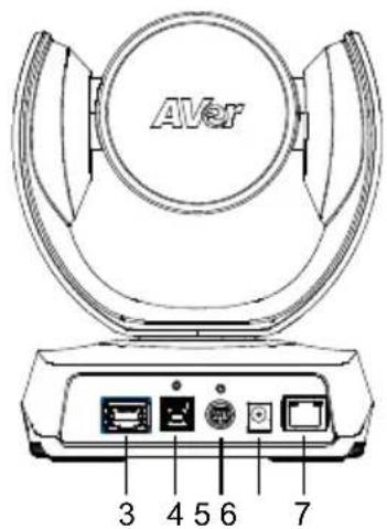
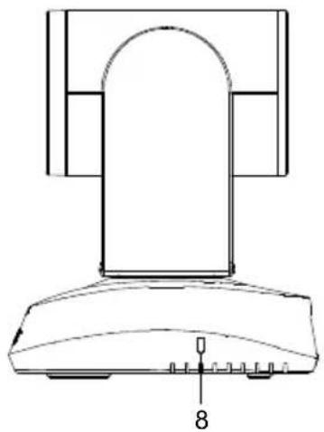
1 Status LED 4 USB 3.1 Type B Port 7 Ethernet Port
2 IR Sensor 5 RS232 In/Out Port 8 Kensington Lock
3 Speakerphone Port 6 DC 12V Power Jack (Blue Cable)
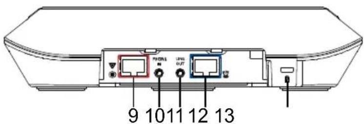
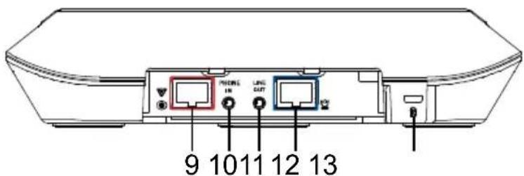
9 Speakerphone Port
(Red Cable, for extended
speakerphone and
microphone connection)
10 Phone In port
11 Line Out port
12 Camera Port (Blue Cable)
13 Kensington Lock
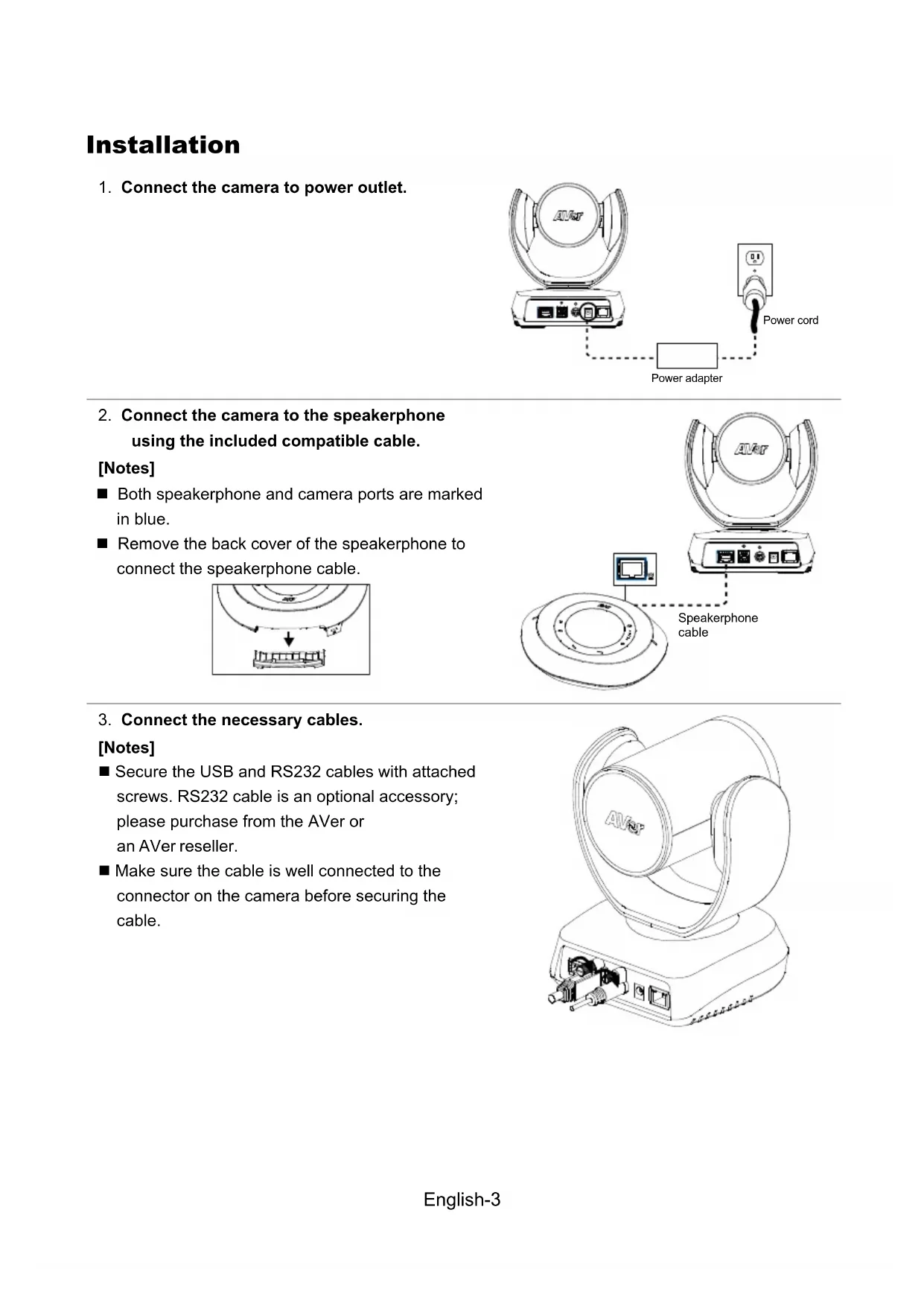
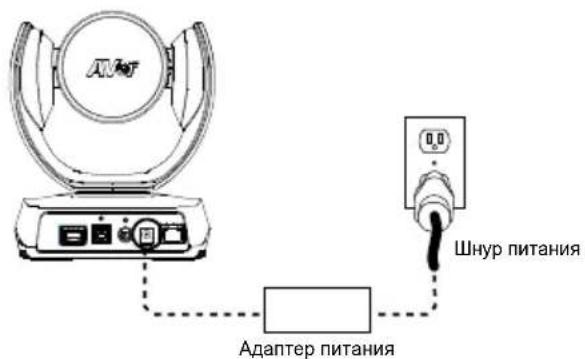
Installation
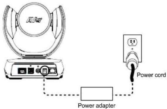
- Connect the camera to power outlet.
- Connect the camera to the speakerphone using the included compatible cable.
[Notes]
- Both speakerphone and camera ports are marked in blue.
- Remove the back cover of the speakerphone to connect the speakerphone cable.
![AVer VC520 Pro2 - [Notes] - 1](/content/2026/03/553471/images/de6875e9f56693e7c3dc621491f8a336912b38689aa0bcc44e7eb8655d7a908e.jpg)
![AVer VC520 Pro2 - [Notes] - 2](/content/2026/03/553471/images/f0ec60bbdfb656ba2dfbf45280c62e6a365b949d506869ccc0483a47569845be.jpg)
- Connect the necessary cables.
[Notes]
- Secure the USB and RS232 cables with attached screws. RS232 cable is an optional accessory; please purchase from the AVer or an AVer reseller.
Make sure the cable is well connected to the connector on the camera before securing the cable.
![AVer VC520 Pro2 - [Notes] - 1](/content/2026/03/553471/images/166836a28f9679c0cd9c87cbdca7726b46b2a2069624163c19bbb2e231a86728.jpg)
4. Connect the camera to the computer/laptop.
[Notes]
Use the USB 2.0 cable included in the package.
VC520 Pro2 has the USB 3.1 port which is USB 2.0 compatible.
Maximum resolution/fps for USB 2.0 and USB 3.1 port are shown below.
| M-JPEG/fps | NV12/fps | YUV/fps |
| USB 2.0 | 1080@/60 fps 720p | @/10 fps | 720p@/10 fps |
| 480p@/30 fps | 480p@/30 fps |
| USB 3.1 | 1080p@/60 fps 1080p | @/30 fps | |
![AVer VC520 Pro2 - [Notes] - 1](/content/2026/03/553471/images/4a89d8dd2296926c560ef7a80f85b879f26c3ea3f46e94753adc2df4539dd9e0.jpg)
Remote Control
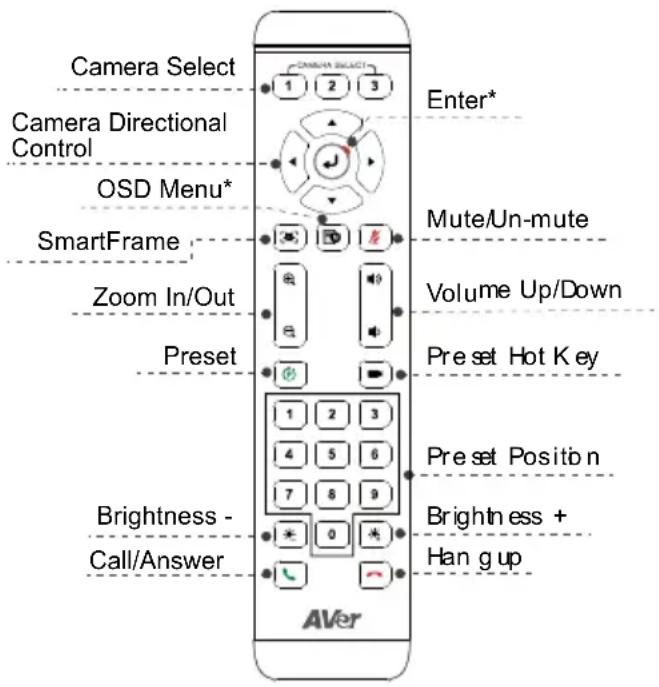
*Not supported for VC520 Pro2
AAA Batteries (required)
- Preset ( ) The Preset button on the remote serves 2 functions.
To Save a Preset - Move camera to desired position. Press and hold the preset button until you receive the save message on the screen. Select preset position button 0-9 to store the current camera position. Repeat steps if needed.
To Load a Preset - Press the preset button and preset position button 0-9 to load a saved camera position. Repeat steps if needed.
Press and hold the number button '' for 1 second to turn on or off the WDR function.
Press and hold the number button ''for1 second to turn on or off the SmartFrame function.
Press and hold the number button 8 for 1 second to enable or disable RTMP streaming function.
Press and hold the number button for 1 second to force camera to enter sleep mode. This will end any video streaming. To wake up the camera, press the button or any directional button for 1 second. This mode is not functional while USB streaming is on.
Camera Select 2 If you only have one camera and do not need to adjust any setting, the default is camera 1. If you press camera 2 or 3 on the remote control, you will find your remote can't control your camera. In this case, please press camera 1 on your remote again.
SmartFrame Press for 1 second to switch the SmartFrame function among Manual Framing/Auto Framing/ Preset Framing modes. A message (as figures shown) will display on the screen to indicate the mode.
Manual Framing
Auto Framing
Preset Framing
[Note] SmartFrame deploys face and body detection technology. People wearing masks and side facial profiles can still be detected. The maximum detection distance is 7-10 meters.
Set up preset points in advance (Only for Preset point 1-9. Preset 0 is for home position).
Wall Mount Installation
-
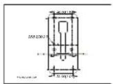
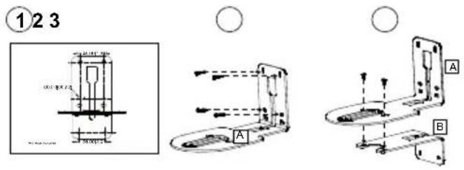
Use the drilling paper included in the package to drill the holes in the wall where the user wants to mount the camera.
-
Use the screws (not included) to secure the L-mount bracket on the wall.
[Note] For cement wall: M4 x20mm self-tapping screws (x4) + Plastic conical anchor For wooden wall: M4 x20mm self-tapping screws (x4)
-
Then, assemble the L-mount brackets A + B with 2 screws (M4 x8mm, included in the package).
-
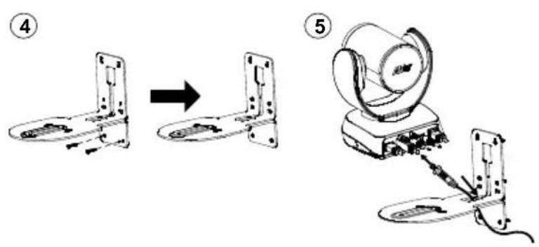
After assembling the L-mount brackets, use the screws (not included) to secure the lower part of L-mount brackets on the wall.
[Note] For cement wall: M4 x20mm self-tapping screws (x2) + Plastic conical anchor. For wooden wall: M4 x20mm self-tapping screws (x2)
-
Pass the cables through the hole on the L-mount brackets and connect the cables to corresponding connection ports.
-
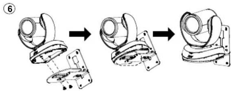
Use the remaining screws (1/4"-20 L=7.5mm, included in the package) to secure the camera on the L-mount brackets.
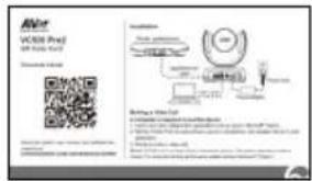
Making a Video Call
A computer is required to use this device.
- Open your video collaboration application such as Zoom, Microsoft Teams, Skype for Business, Skype, Google Meet, Intel Unite™, RingCentral, BlueJeans, V-Cube, LiveOn, CyberLink U Meeting, TrueConf, Adobe Connect, Cisco WebEx®, Fuze, GoToMeeting™, Microsoft Sync™, Vidyo, vMix, WebRTC, Wirecast, XSplit.
- Set the VC520 Pro2 as your primary camera device in your application (Please consult your application setup guide for details).
- Ready to make a video call.
[Note] VC520 Pro2 is a Plug-n-Play Conference Camera. The system requires no special drivers. For advanced setting and firmware update, please download PTZApp 2.
Making a Connection through the Browser
VC520 Pro2 has an Ethernet port for IP streaming and allows administrators to remotely control and set up the camera via an internet access. Moreover, VC520 Pro2 also supports RTSP and RTMP functions. For more details, please refer to user's manual or contact our technical support.
- Make sure the VC520 Pro2 has an internet access connection.
- Launch PTZApp 2^* (PTZ) and connect VC520 Pro2 to PC with USB cable.
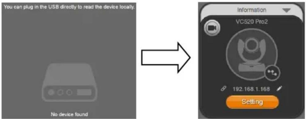
- The camera default IP address is 192.168.1.168. Click pencil icon ( ) to edit IP address**.
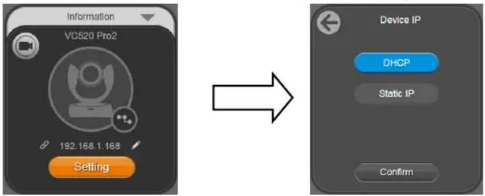
- Click webblink icon ( ) to launch Chrome page. Please enter the password (default password is aver4321).
[Note] The browser supports:
-
Chrome: version 76.x or above
-
Firefox: version 69 or above
-
IE: Doesn't support
-
After editing IP address, user can access web settings of the camera with only Ethernet cable connection. Unplug the USB cable.
-
The main web screen is displayed as below.
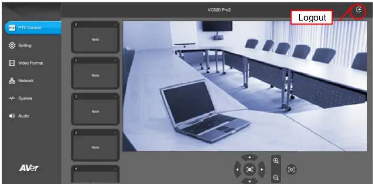
- In PTZApp2, user can change the IP address setting of VC520 Pro2, configure the parameters of the camera, set up AI tracking functions and some advanced image settings, pan, tilt, and zoom the camera. Please refer to the user manual for details.
Please go to https://www.aver.com/download-center (Global & European Headquarters) or https://www.averusa.com/business/support/ (USA) to download the PTZApp 2. After downloading, double-click on the file and follow the on-screen instructions to complete the installation. After installing the PTZApp 2, double-click on the PTZApp 2 icon to run the application.
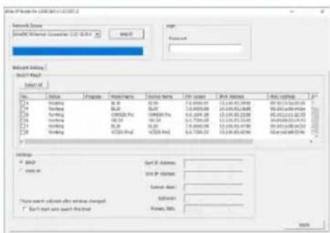
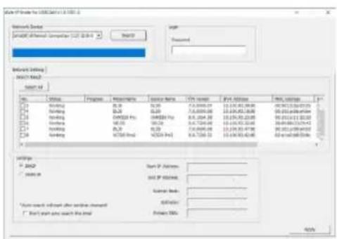
** To support IP address changes in groups, user can download AVer IP Finder app.
- Download the IP Finder from https://www.aver.com/download-center (Global & European Headquarters) or https://www.averusa.com/business/support/ (USA).
- Run the IP Finder.
- Click "Search", and all available devices will be listed on the screen.
English-8
FEDERAL COMMUNICATIONS COMMISSION
NOTE: This equipment has been tested and found to comply with the limits for a Class A digital device, pursuant to part 15 of the FCC Rules. These limits are designed to pro-ride reasonable protection against harmful interference when the equipment is operate din a commercial environment. This equipment generates, uses, and can radiate radiofrequency energy and, if not installed and used in accordance with the instruction manual, may cause harmful interference to radio communications. Operation of this equipment in a residential area is likely to cause harmful interference in which case the user will be required to correct the interference at his own expense.
FCC Caution: Any changes or modifications not expressly approved by the party responsible for compliance could void the user's authority to operate this equipment.
This device complies with part 15 of the FCC Rules. Operation is subject to the following two conditions: (1) This device may not cause harmful interference, and (2) this device must accept any interference received, including interference that may cause undesired operation.
Warning:
This is a class A product. In a domestic environment this product may cause radio interference in which case the user may be required to take adequate measures.
This Class A digital apparatus complies with Canadian ICES-003.
Caution:
Risk of Explosion if Battery is replaced by an Incorrect Type. Dispos of Used Batteries According to the Instructions.
COPYRIGHT
©2021 AVer Information Inc. All rights reserved.
MORE HELP
For FAQs, technical support, software and user manual download, please visit:
Global: https://www.aver.com/download-center/
USA: https://www.averusa.com/business/support/
European Headquarters: https://www.aver.com/download-center/
Technical Support:
Global: https://aver.com/technical-support
USA: https://averusa.force.com/support/s/contactsupport
European Headquarters: https://www.aveurope.com/technical-support/
Global
AVer Information Inc.
https://www.aver.com
8F, No.157, Da-An Rd.,
Tucheng Dist.,
New Taipei City 23673,
Taiwan
Tel: +886 (2) 2269 8535
USA
AVer Information Inc.
https://www.averusa.com
668 Mission Ct.,
Fremont, CA 94539
Tel: +1(408) 263 3828
Toll-free: +1 (877) 528 7824
Technical support: support.usa@aver.com
European Headquarters
AVer Information Europe B.V.
https://www.aveurope.com
Westblaak 140,3012KM
Rotterdam, Netherlands
Tel: +31(0) 107600550
Technical support: eu.rma@aver.com
包装内容物
https://www.averusa.com/business/support/ (美國)下載IP Finder。
https://www.aver.com
https://www.aver.com
新北市土城区大安路157号8楼
电话:(02)2269-8535
八夕一内容
力本体 一九本体
電源&電源一

©2021 AVer Information Inc. All rights reserved.
その他的さ木一ト
■ 今者をは“8”1。通言:RTMP能将歌造如
↑ 對者を説言:“9”将1部通不
上和
上,都的也。
KAMA SECT
■ KamaRa SeIbIK(1)KamaRaHa
HahDaIgSeIeJyIiJiJiJiJiJiJiJiJiJiJiJiJiJiJiJiJiJiJiJiJiJiJiJiJiJiJiJiJiJiJiJiJiJiJiJiJiJiJiJiJiJiJiJiJiJiJiJiJiJiJi
SmartFrame:1主同不
Manual Framing
Auto Framing
Preset Framing
[摺]SmartFrame是elglf且inctgj
g也成用。,aKsKt 1
sAina 8eelgluBtoBisn sAondo
gatshs 7-10MteIi.
FRII FIOINTE MI RSE 0
朝 云
https://www.aver.com/download-center(glorobel及yL
https://www.averusa.com/business/support/(M国)罗伊同法有PTZApp2将d运理上
- IP Finder https://www.aver.com/download-center (glorobel 吗 吾陵 贝默)
http://www.averusa.com/business/support/(民国)出版社
- IP Finder 1
- “鍾” 1
©2021 AVer Information Inc. All rights reserved.
季夫 云
https://www.aver.com
8F, No.157, Da-An Rd., Tucheng Dist.,
New Taipei City 23673, Taiwan
Tel: +886 (2) 2269 8535
Siège européen
AVer Information Europe B.V.
https://www.aveurope.com
Westblaak 140, 3012KM, Rotterdam, Pays-Bas
Tel: +31 (0) 107600550
Assistance technique: EU.RMA@aver.com
https://www.aver.com
8F, No.157, Da-An Rd., Tucheng Dist.,
New Taipei City 23673, Taiwan
Tel.: +886 (2) 2269 8535
Sede europea
AVer Information Europe B.V.
https://www.aveurope.com
Westblaak 140, 3012KM, Rotterdam, Netherlands
Tel.: +31 (0) 10 7600 550
Sopporté professionnel: EU.RMA@aver.com
KoMnJIeKT noCTaBKn
4 IopT USB 3.1 (Tuna B)
5 IopT BBOda/BbIBOda RS232
6 He3o nHTaHn 12B (noct.
7 NopT Ethernet
8 3amok Kensington
9 Iopr pomko CB3n
(красьи Ka6eNB,Дпя
COeINHeHnC
DONOHHTeJIbHbIMN
yCTpOINCTBAMn rPOMKoI
CB83N MNUKPOOHOHAMU
10 NoprPHONE IN
11 Nopt LINE OUT
12 NopT KaMepbI (CnHn Ka6enb)
13 3amok Kensington
yctahOBka
- Побъдени Te KaMepy K элктpopo3eTke.
https://www.aver.com
8F, No.157, Da-An Rd., Tucheng Dist.,
New Taipei City 23673, Taiwan
Tel.: +886 (2) 2269 8535
Ebponeicka 7Ta6-KBapTnpa
AVer Information Europe B.V.
https://www.aveurope.com
Westblaak 140, 3012KM, Rotterdam, Netherlands
Tel: +31 (0) 10 7600 550
Texnuecka noidepka EU.RMA@aver.com