
DTM01P - Toilet DOMETIC - Free user manual and instructions
Find the device manual for free DTM01P DOMETIC in PDF.
| Product type | Black water tank level monitor |
| Brand | Dometic |
| Model | DTM01P |
| Article number | 9108688891 |
| Power supply | 12 V === or 24 V === |
| Current consumption | 0.016 A (average) |
| Required fuse | 0.5 A (not supplied) |
| Panel frame material | ABS |
| Indicator panel material | Polyester |
| Level sensor bulb material | Nitrile rubber |
| Indicator | Red indicator light "Tank full" |
| Main function | Indicates the full level of the black water tank to prevent overflow |
| Intended use | Monitoring of black water or gray water tanks (not fuel) |
| Sensor type | Sensor with level bulb, 32 mm opening |
| Recommended cable cross-section | 1 mm² (copper) |
| Certifications | ISO8846, EMC Directive 2004/108/EC |
| Warranty | Legal (see store conditions) |
| Disposal | Recyclable packaging, product to be disposed of at a recycling center |
| Safety instructions | Do not use in explosive atmospheres; do not install in a fuel tank |
Frequently Asked Questions - DTM01P DOMETIC
User questions about DTM01P DOMETIC
0 question about this device. Answer the ones you know or ask your own.
Ask a new question about this device
Download the instructions for your Toilet in PDF format for free! Find your manual DTM01P - DOMETIC and take your electronic device back in hand. On this page are published all the documents necessary for the use of your device. DTM01P by DOMETIC.
USER MANUAL DTM01P DOMETIC
natural_image
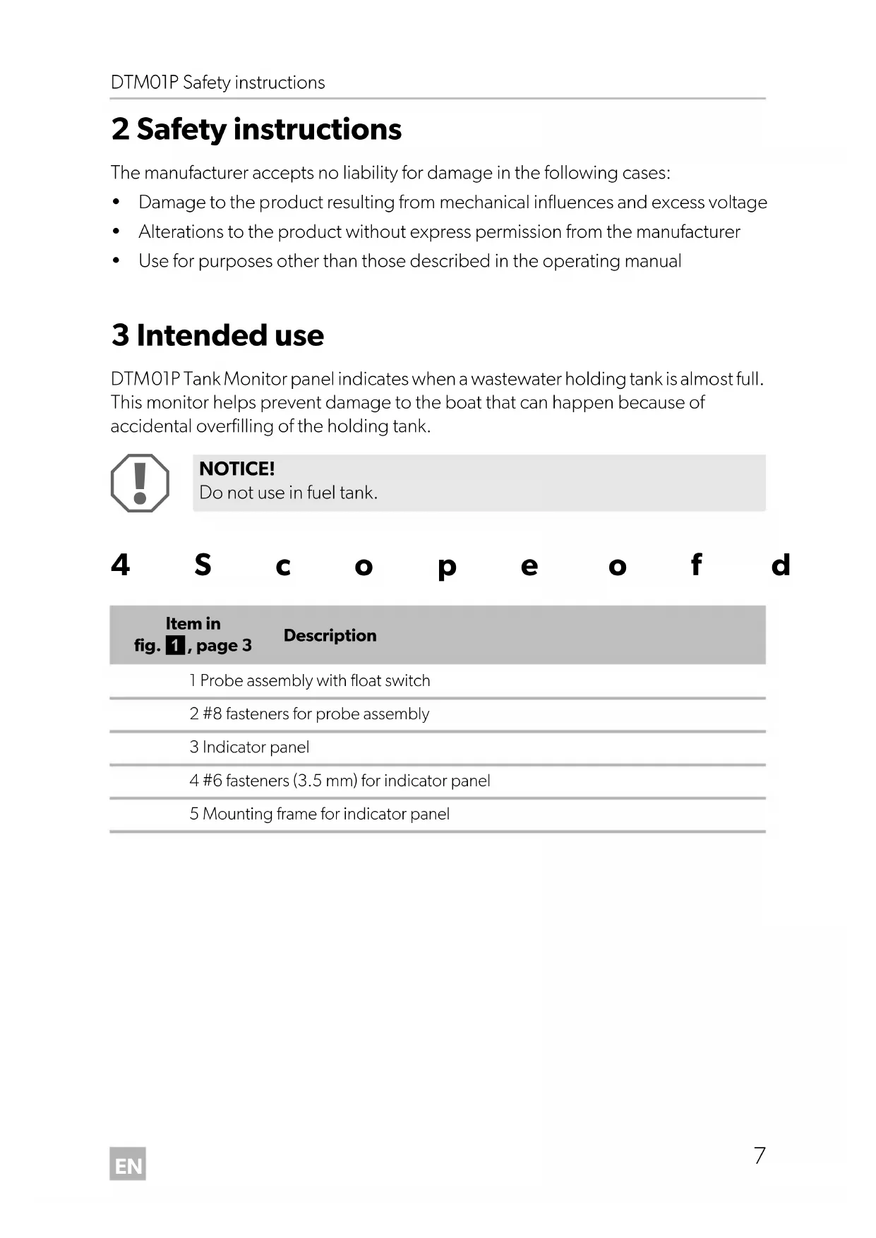
Exterior view of a black Full Tank and a white mechanical support bracket (no text or symbols on the main components)DTM01P
EN Tank monitor Installation Manual....6
natural_image
Simple line drawing of a water tank connected to a control panel (no text or symbols)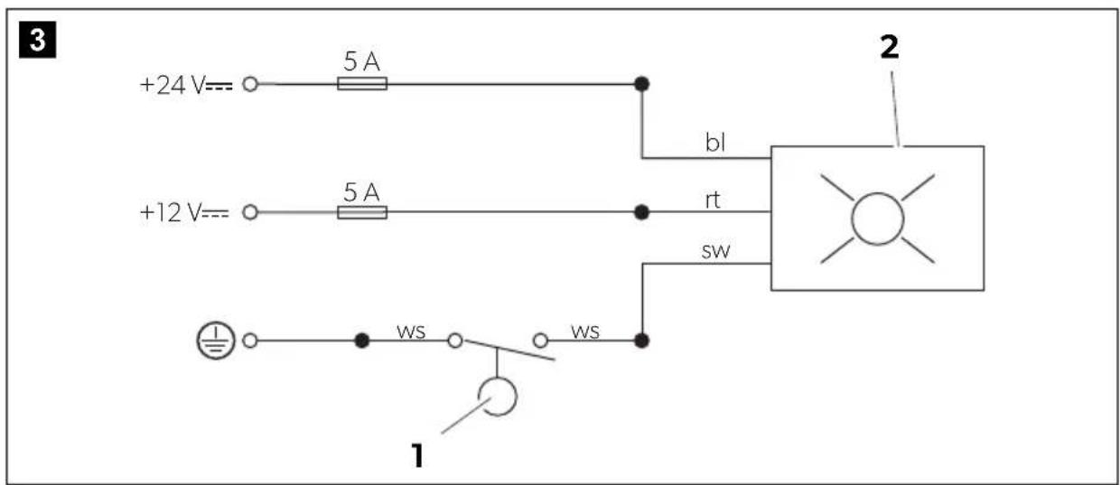
natural_image
Technical line drawing of a mechanical assembly with screws and a cylindrical base (no text or symbols)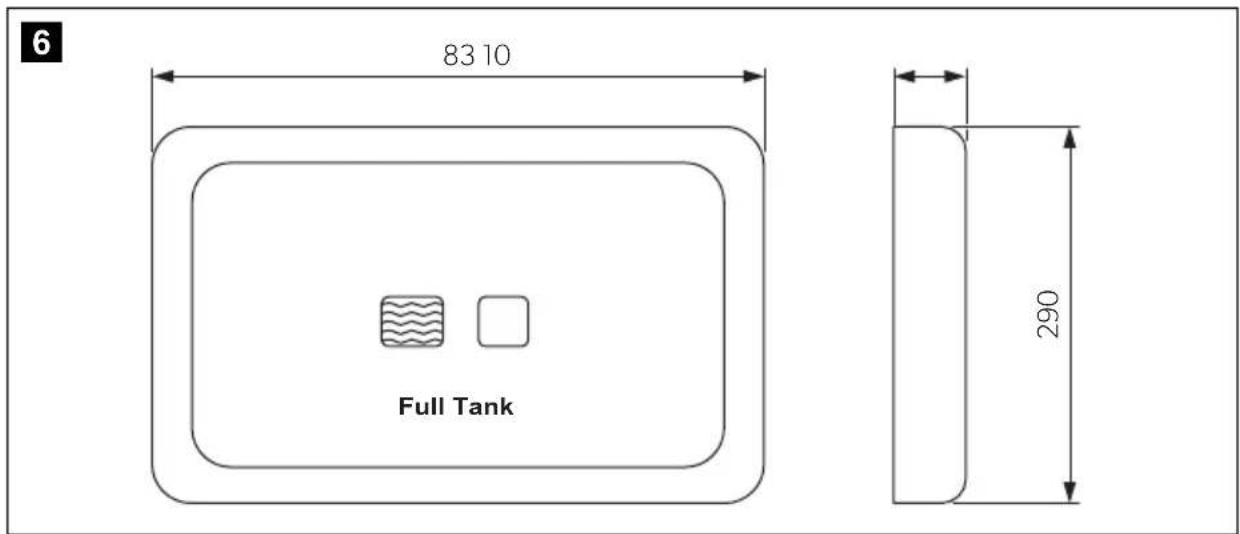
7
8
Please read this instruction manual carefully before installation and first use, and store it in a safe place. If you pass on the product to another person, hand over this instruction manual along with it.
Contents
1 Explanation of symbols....6
2 Safety instructions....7
3 Intended use ....7
4 Scope of delivery 7
5 Technical description ....8
6 Installation....8
7 Warranty ....11
8 Disposal....11
9 Technical data....11
1 Explanation of symbols

CAUTION!
Safety instruction: Failure to observe this instruction can lead to injury.

NOTICE!
Failure to observe this instruction can cause material damage and impair the function of the product.

NOTE
Supplementary information for operating the product.
2 Safety instructions
The manufacturer accepts no liability for damage in the following cases:
- Damage to the product resulting from mechanical influences and excess voltage
• Alterations to the product without express permission from the manufacturer - Use for purposes other than those described in the operating manual
3 Intended use
DTM01P Tank Monitor panel indicates when a wastewater holding tank is almost full. This monitor helps prevent damage to the boat that can happen because of accidental overfilling of the holding tank.

NOTICE!
Do not use in fuel tank.
4 S c o p e o f d
Item in fig. 1, page 3 Description
1 Probe assembly with float switch
2 #8 fasteners for probe assembly
3 Indicator panel
4 #6 fasteners (3.5 mm) for indicator panel
5 Mounting frame for indicator panel
5 Technical description

NOTICE!
Operator must know local regulations for emptying a holding tank.
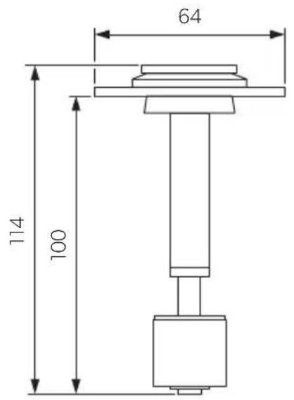
5.1 Probe assembly with float switch
The probe assembly installs into a 32 mm diameter opening on the top of a Dometic holding tank or other holding tank. As the level of holding tank contents rises, the float switch inside the tank is pushed upward and activates the "Full Tank" light on the indicator panel.
5.2 Indicator panel
The indicator panel has a single light which is activated by the float switch inside the holding tank. When the "Full Tank" light is activated, the operation of any plumbing fixture connected to the holding tank should stop until the tank is emptied.
6 Installation
6.1 Overview
For general installation layout see fig. 2, page 3.
Wiring diagram: fig. 3, page 3.
Key to Wiring diagram
Item Description
| 1 Float switch |
| 2 Indicator panel |
| bl Blue |
| rt Red |
| sw Black |
| ws White |
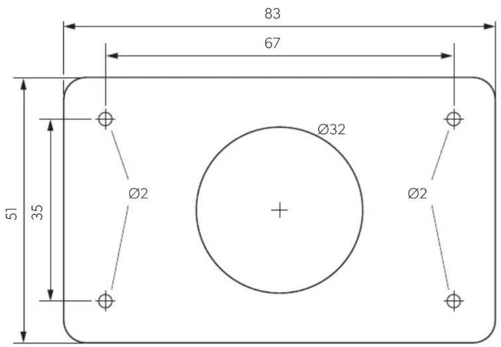
Indicator panel template: fig. 8, page 5.
6.2 Indicator panel

CAUTION!
Do not install indicator panel in an atmosphere with potentially flammable or explosive vapors.
When selecting the installation location observe the following information:
- Select panel location away from direct contact with water and oil.
- Confirm clearance of 50 mm for wire connections behind wall, hull liner or bulk-head.
- Make sure the electrical power is shut off.

NOTE
For electrical connections refer to wiring diagram (fig. 3, page 3).
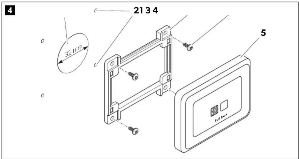
Install the indicator panel as follows (fig. 4, page 4):
▶ Using indicator panel template, cut out panel access hole (1) and drill fastener holes (2).

NOTE
Make sure wires extend out through access hole (1).
▶Route 1 mm ^2 stranded copper wire from power source, through 0.5 A fuse (not provided), to panel location.
▶Route 1 mm ^2 stranded copper wire from holding tank probe assembly to panel location.
▶ Install mounting frame (3) with four #6 (3.5 mm) fasteners (4).
▶ Make proper 12 V== or 24 V== wiring connections to indicator panel (5).
▶ Push indicator panel (5) onto mounting frame (3) until it locks into place.
6.3 Probe assembly

CAUTION!
Do not use probe assembly in fuel tank.
Never install the probe assembly with float switch in tank that contains anything other than wastewater, gray water or fresh water.
Make sure the electrical power is shut off.

NOTE
For installation in sailboats: Locate probe assembly on athwartships centerline of tank to assure accuracy when heeled.
Install the probe as follows:
▶Route 1 mm ^2 stranded copper wire from DC ground source to probe assembly.
▶ Using quick-disconnect terminals, make proper wiring connections from DC ground source and indicator panel to probe assembly wires (refer to wiring diagram: fig. 3, page 3).
▶ Select probe assembly location away from other tank fittings.
▶Drill 32 mm diameter hole in top of tank.
▶ Place probe assembly into center of hole.
▶Mark four fastener locations at corners.
▶Remove probe assembly from hole.
▶Drill fastener holes with 3 mm drill bit.
▶With probe assembly removed from tank, turn on electrical power to system.
▶ Move black float up and down to assure proper operation of float and indicator light.
Red indicator light should illuminate when float is pushed up.
▶After successful test turn off electrical power.
▶Disconnect wires at quick-connect terminals.
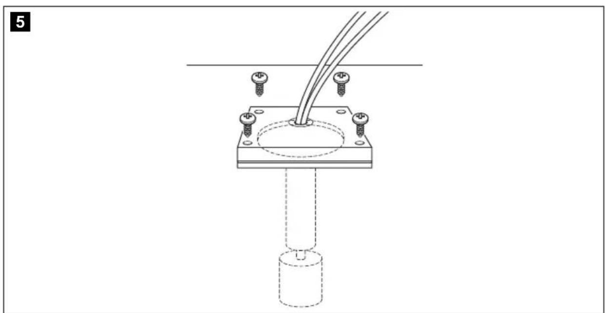
▶Place probe assembly into hole in top of holding tank.
▶ Use four #8 fasteners (4 mm) to secure probe assembly into holding tank (fig. 5, page 4).
▶Re-connect wires.
▶Turn on electrical power.
7 W a r r a n t y
The statutory warranty period applies. If the product is defective, please contact your retailer or the manufacturer's branch in your country (see the back of the instruction manual for the addresses).
For repair and guarantee processing, please include the following documents when you send in the device:
• A copy of the receipt with purchasing date
- A reason for the claim or description of the fault
8 D i s p o s a l
▶ Place the packaging material in the appropriate recycling waste bins wherever possible.

If you wish to finally dispose of the product, ask your local recycling centre or specialist dealer for details about how to do this in accordance with the applicable disposal regulations.
9 Technical data
| Tank Monitor DTM01P | |
| Ref. no.: 9108688891 | |
| Material | |
| Panel frame: ABS | |
| Panel: Polyester | |
| Float switch: Nitrile rubber ebonite | |
| Average current consumption: | 0.016 A at 12 V--- |
| Fuse: | 0.5 A |
| Dimensions | |
| Indicator panel: | see fig. 6, page 4 |
| Probe: | see fig. 7, page 5 |
| Approvals: | ISO8846EMC Directive 2004/108/EC |


Brand : DOMETIC
Model : DTM01P
Category : Toilet