NikolaTesla Prime PRF0155874 - Cooker ELICA - Free user manual and instructions
Find the device manual for free NikolaTesla Prime PRF0155874 ELICA in PDF.



User questions about NikolaTesla Prime PRF0155874 ELICA
0 question about this device. Answer the ones you know or ask your own.
Ask a new question about this device
Download the instructions for your Cooker in PDF format for free! Find your manual NikolaTesla Prime PRF0155874 - ELICA and take your electronic device back in hand. On this page are published all the documents necessary for the use of your device. NikolaTesla Prime PRF0155874 by ELICA.
USER MANUAL NikolaTesla Prime PRF0155874 ELICA
EN Instruction on mounting and use
text_image
QR code image containing encoded data, no visible human-readable text

text_image
QR code image containing encoded data, no visible human-readable textEN WATCH THE INSTALLATION VIDEO
IT GUARDA IL VIDEO DI INSTALLAZIONE
FR REGARDEZ LA VIDÉO D'INSTALLATION
text_image
QR code displayed on a smartphone screen, alongside a separate QR code illustration.Scan QR code
Watch the video
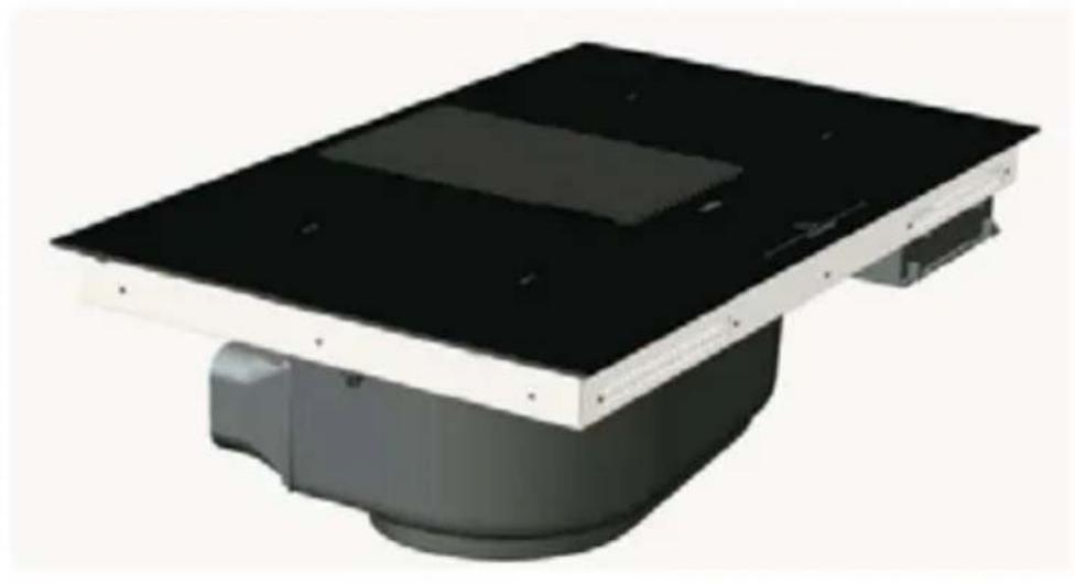
natural_image
3D rendering of a black rectangular electronic device with a flat top and internal compartments (no text or symbols visible)
text_image
Warning symbol with exclamation mark, cross symbol, and human figures
text_image
Warning symbol and illustration of a hand holding a glove, indicating hazard or caution.
natural_image
Simple line icon of a house with an upward arrow, no text or symbols present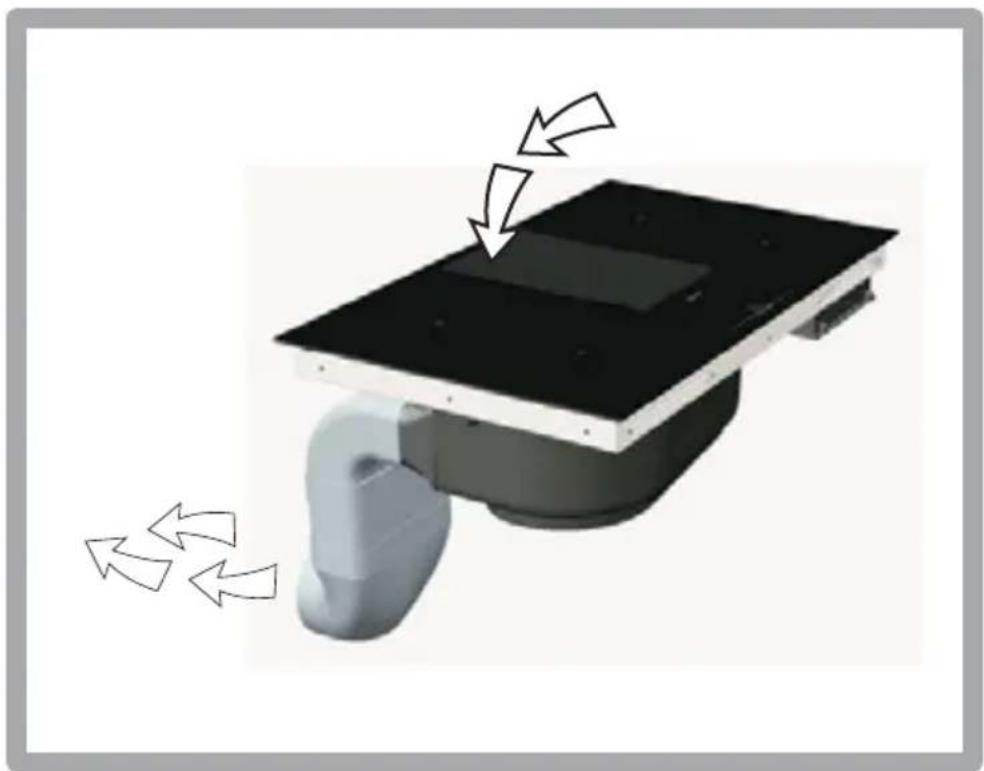
natural_image
3D rendering of a robotic device with a black top and curved arm, showing directional arrows indicating motion (no text or symbols)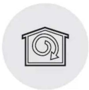
natural_image
Simple line icon of a house with a spiral arrow inside, enclosed in a circular frame (no text or symbols)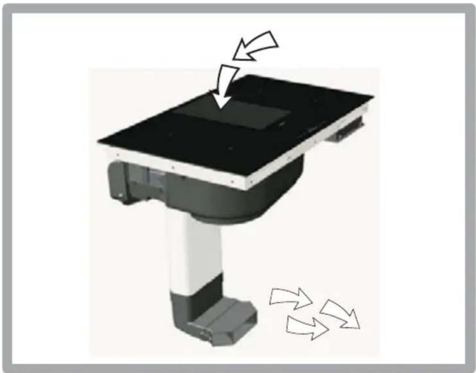
natural_image
3D rendering of a robotic device with directional arrows indicating motion or force (no text or symbols)

1x

2,8 m
text_image
x8 x4 x4 *
2x

1x
1x
natural_image
Simple line drawing of a 3D rectangular prism with no text or symbols
natural_image
Line drawing of a 3D rectangular box or container (no text or symbols)4x
natural_image
Exploded view diagram of a smart air conditioner unit with exploded view and component details (no text or labels)
1x
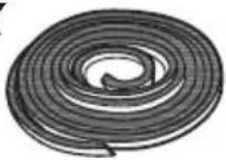
2,8 m
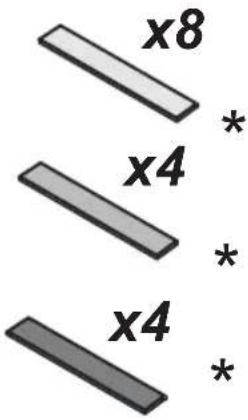
text_image
x8 x4 x4 *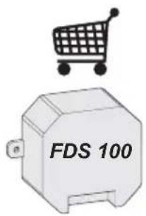
text_image
FDS 1002x

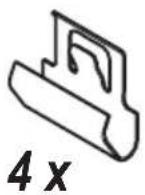
2x
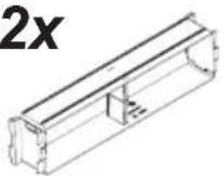
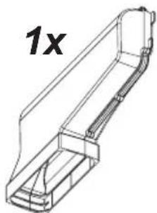
natural_image
Technical line drawing of a mechanical component with no visible text or symbols2x

1x
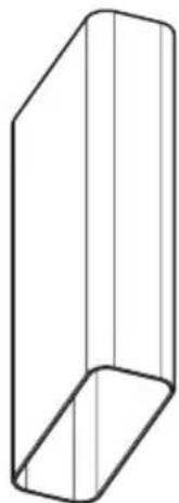
natural_image
Simple line drawing of a 3D rectangular prism with no text or symbols1x
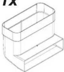
natural_image
Isometric line drawing of a two-tiered rectangular container (no text or symbols)1x
natural_image
Simple line drawing of a rectangular box (no text or symbols)
natural_image
Technical line drawing of a mechanical bracket or support structure with no visible text or symbols2x

1x
natural_image
Technical line drawing of a mechanical component with no visible text or symbols4x
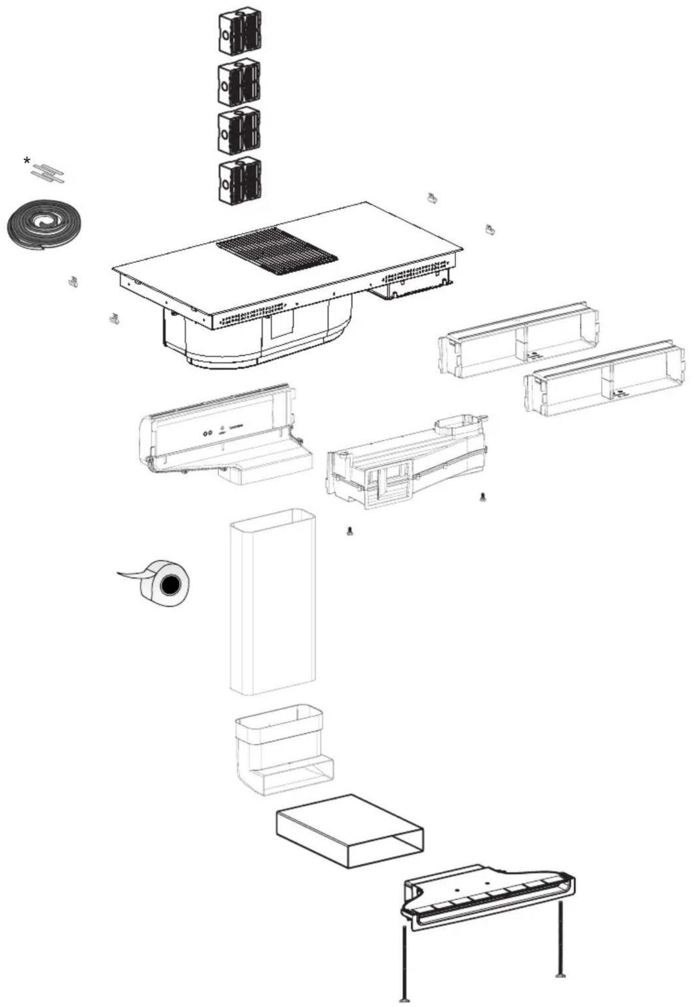
natural_image
Exploded view diagram of a smart air conditioner unit with exploded views and component labels (no text or symbols)
KIT FDS 100
natural_image
Simple line drawing of a door with sound waves and a square button (no text or symbols)
natural_image
Diagram of a vehicle with sensor array and warning sign (no text or symbols)
natural_image
Technical line drawing of a device with a battery cover and a lightning bolt symbol, no text or labels present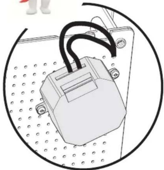
natural_image
Technical line drawing of a mechanical component with a looped base and mounting holes (no text or symbols)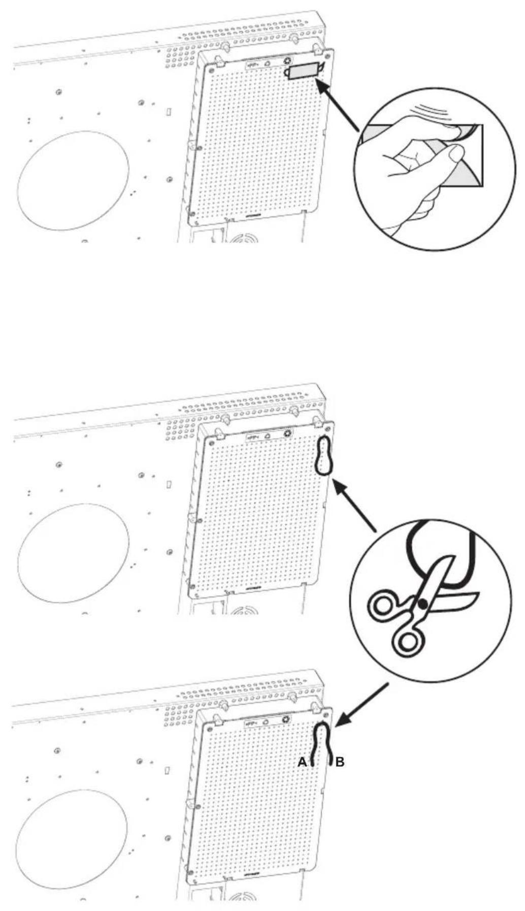
text_image
A B FDS 100 2x 2,9x9,5mm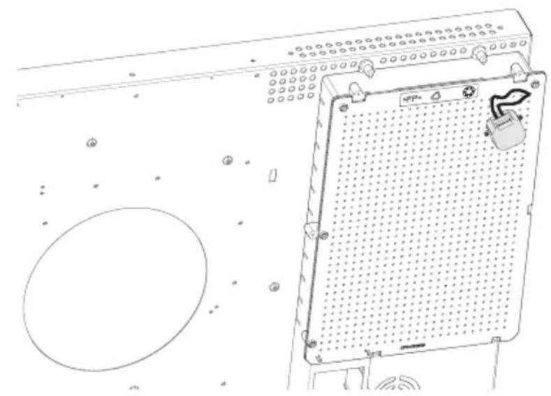
natural_image
Technical line drawing of an electronic device with a grid panel and circular base (no text or symbols)FDS100
text_image
1F 2 3 L N 5A 230 V AC CE N L A B
natural_image
Simple line drawing of a door with an arrow pointing to the interior panel (no text or symbols)
natural_image
Diagram of a device with airflow arrows indicating downward motion (no text or symbols)
natural_image
Simple line drawing of a rectangular frame with horizontal lines inside, no text or symbols present.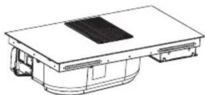
natural_image
Technical line drawing of a mechanical or electronic component with a flat top and curved base (no text or symbols)
natural_image
Abstract black-and-white graphic of a fan-like shape with intersecting lines (no text or symbols)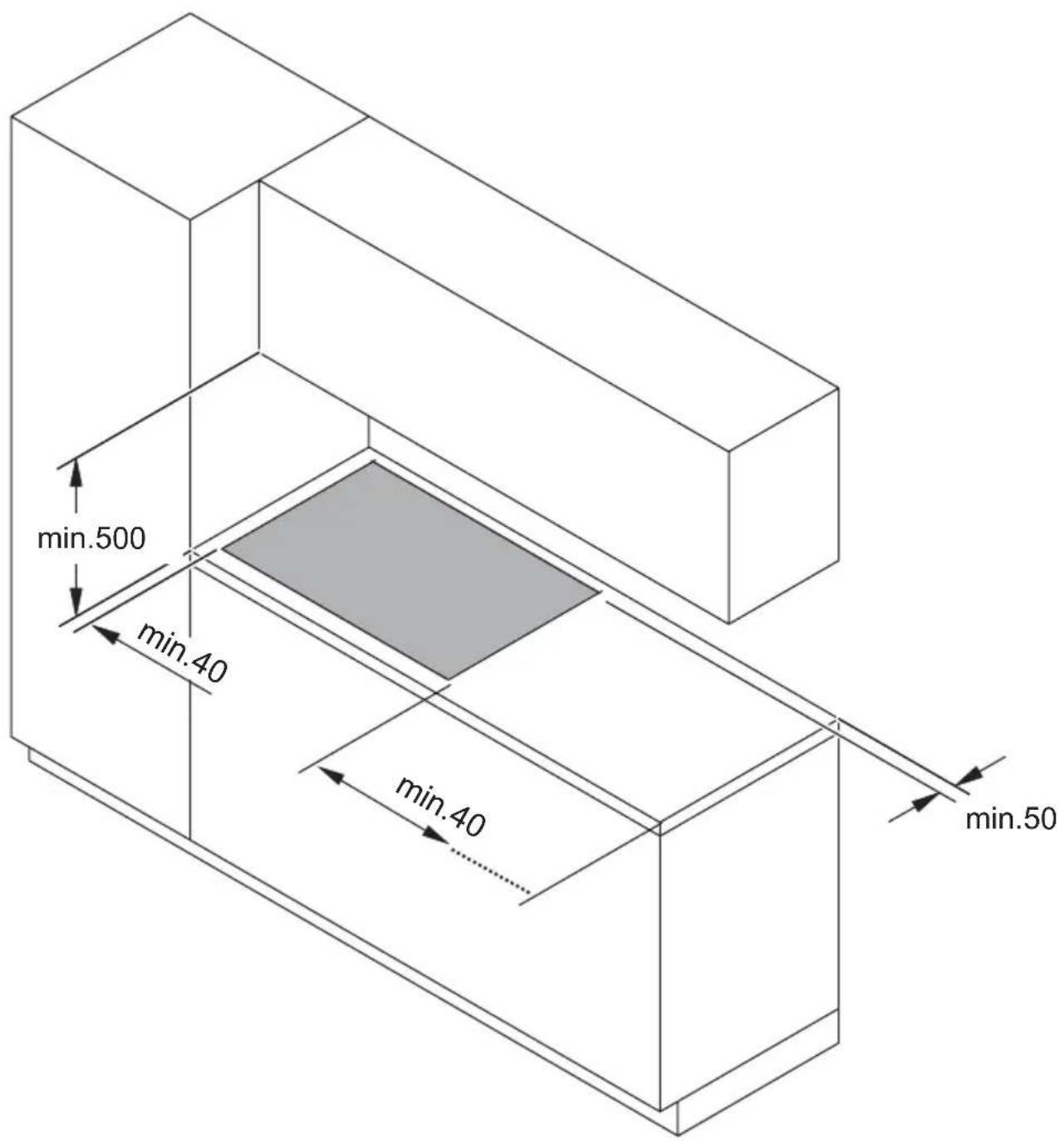
text_image
min.500 min.40 min.40 min.50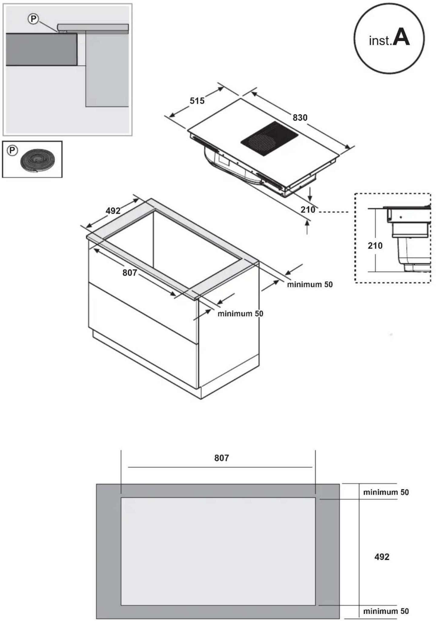
text_image
.a .b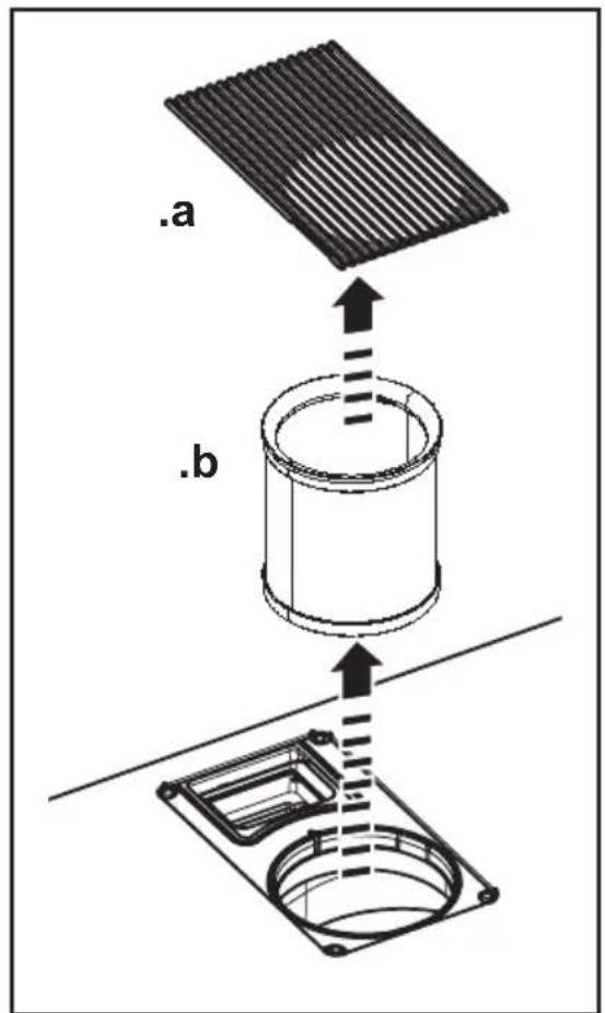
text_image
.a .b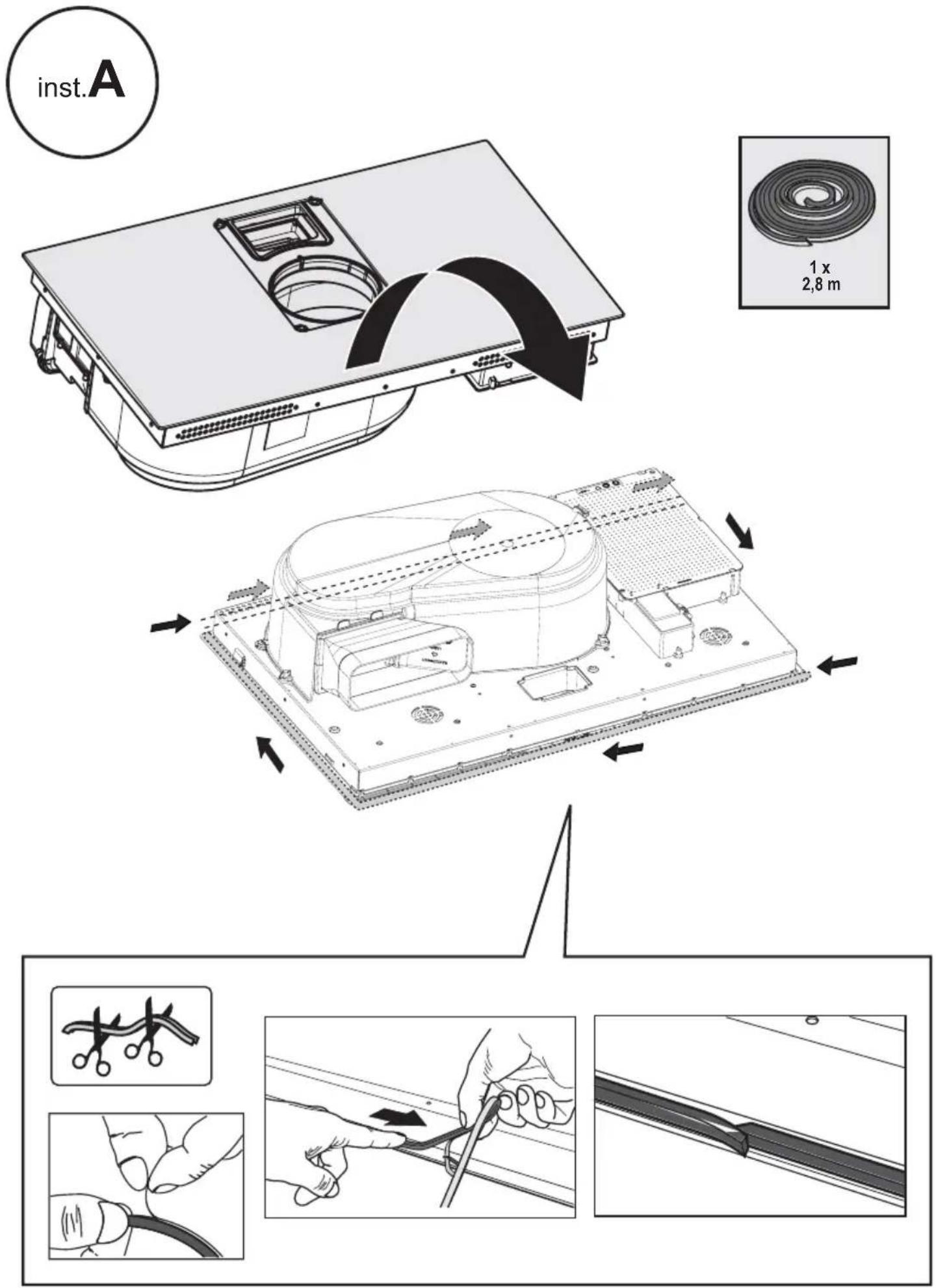
3
natural_image
Technical line drawing of a computer monitor base with an inset showing a component (no text or symbols present)
natural_image
Technical illustration of a mechanical switch mechanism with an inset close-up showing internal components (no text or symbols)
text_image
3x3a
220V-240V \~ 50Hz/60Hz
text_image
0Hz/60Hz 220V 240V L 1 2 3 2x -1x- 4 N380V-415V \~ 50Hz/60Hz
2N\~
natural_image
Simple line drawing of a U-shaped object with two protrusions, labeled '1x' below (no other text or symbols)
text_image
-2x-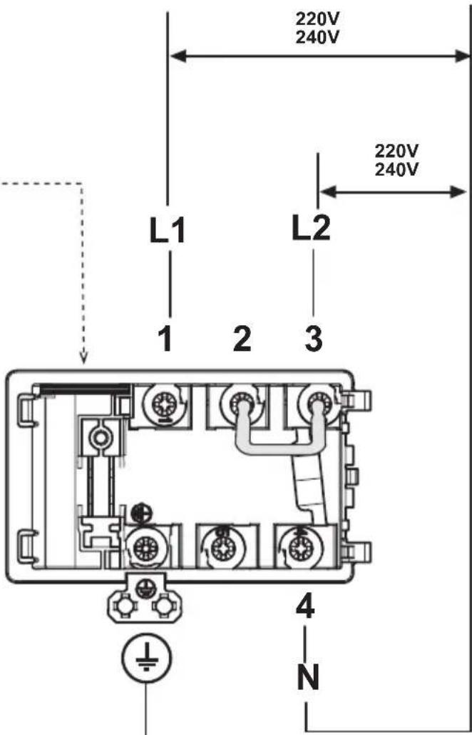
text_image
220V 240V L1 L2 220V 240V 1 2 3 4 N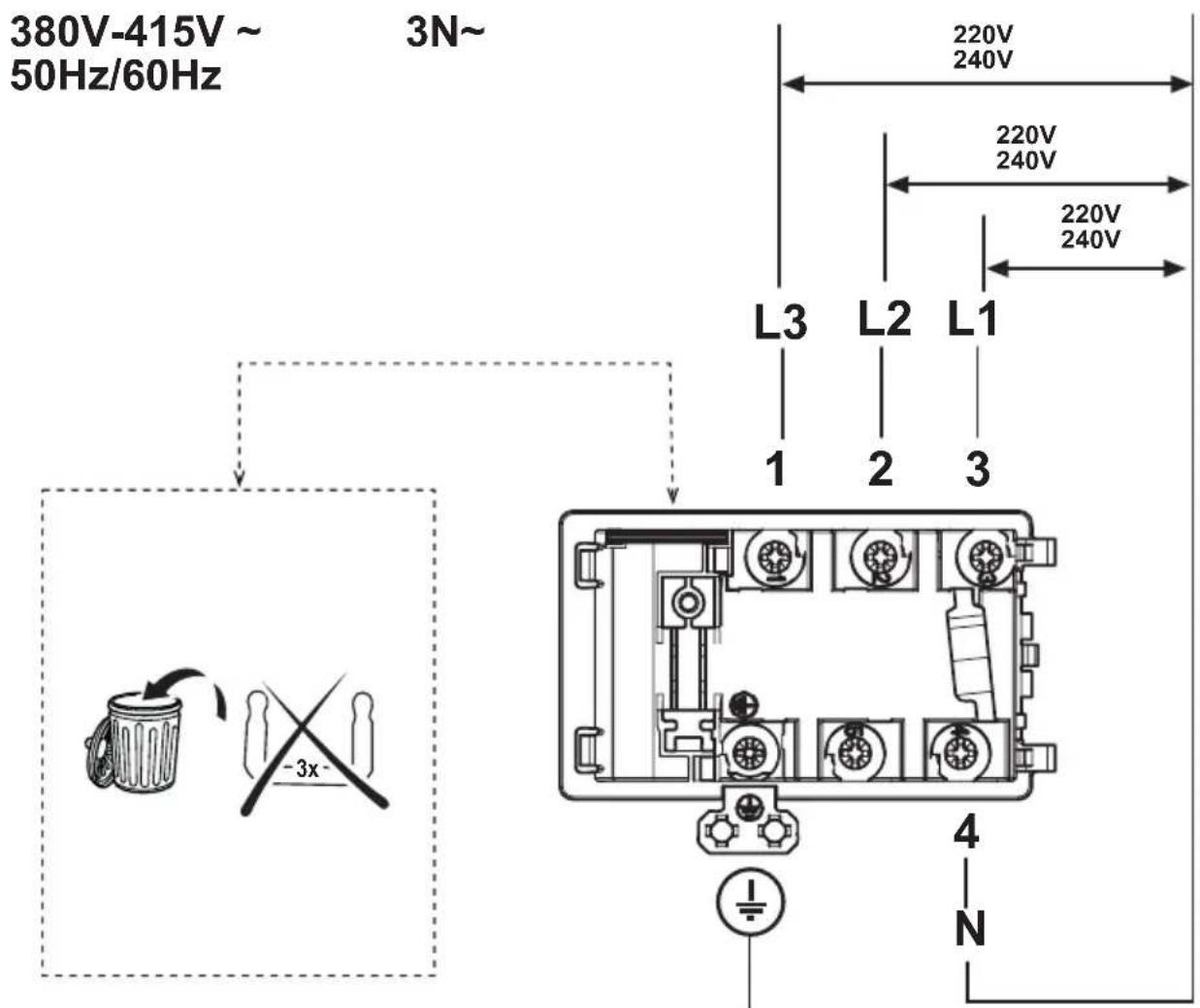
text_image
380V-415V ~ 50Hz/60Hz 3N~ 220V 240V 220V 240V L3 L2 L1 1 2 3 -3x 4 N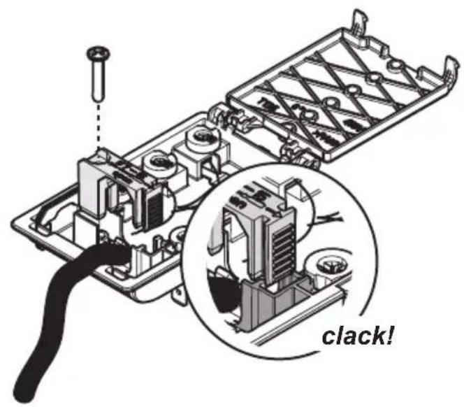
text_image
clack!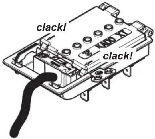
text_image
clack! clack!3c
natural_image
Isometric line drawing of a rectangular box with internal compartments and directional arrows indicating flow or movement (no text or symbols)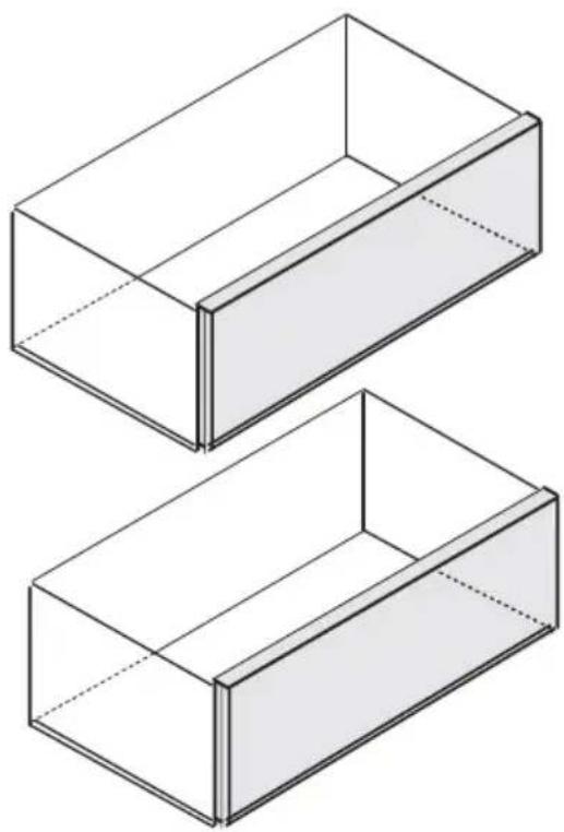
natural_image
Two isometric wireframe views of rectangular storage compartments (no text or symbols)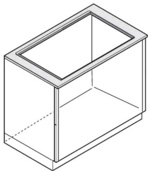
natural_image
Isometric line drawing of a rectangular box with a recessed top (no text or symbols)OK!
natural_image
Simple line drawing of a mechanical component with no text or symbols
natural_image
Technical line drawing of a mechanical assembly with mounting brackets and a central vent (no text or symbols)
text_image
OK!
text_image
x8 x4 inst. B
natural_image
Simple line icon of a house with an upward arrow, no text or symbols present
natural_image
3D rendering of a mechanical device with black and white components, no visible text or symbols7a.1
text_image
①
text_image
.a . b FRONT BACK7a.2

natural_image
Technical line drawing of a rectangular enclosure with internal components and two circular insets showing close-ups of the top view (no text or symbols)7a.3
flowchart
graph TD
    A["Component Open"] --> B["Step 2: Internal Air Condition"]
    B --> C["Step 3: Internal Air Condition"]
    C --> D["Step 4: Internal Air Condition"]
    D --> E["Step 5: Internal Air Condition"]
    E --> F["Step 6: Final Package"]
text_image
① ② ③ ④ ⑤ ⑥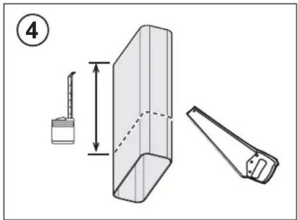
text_image
④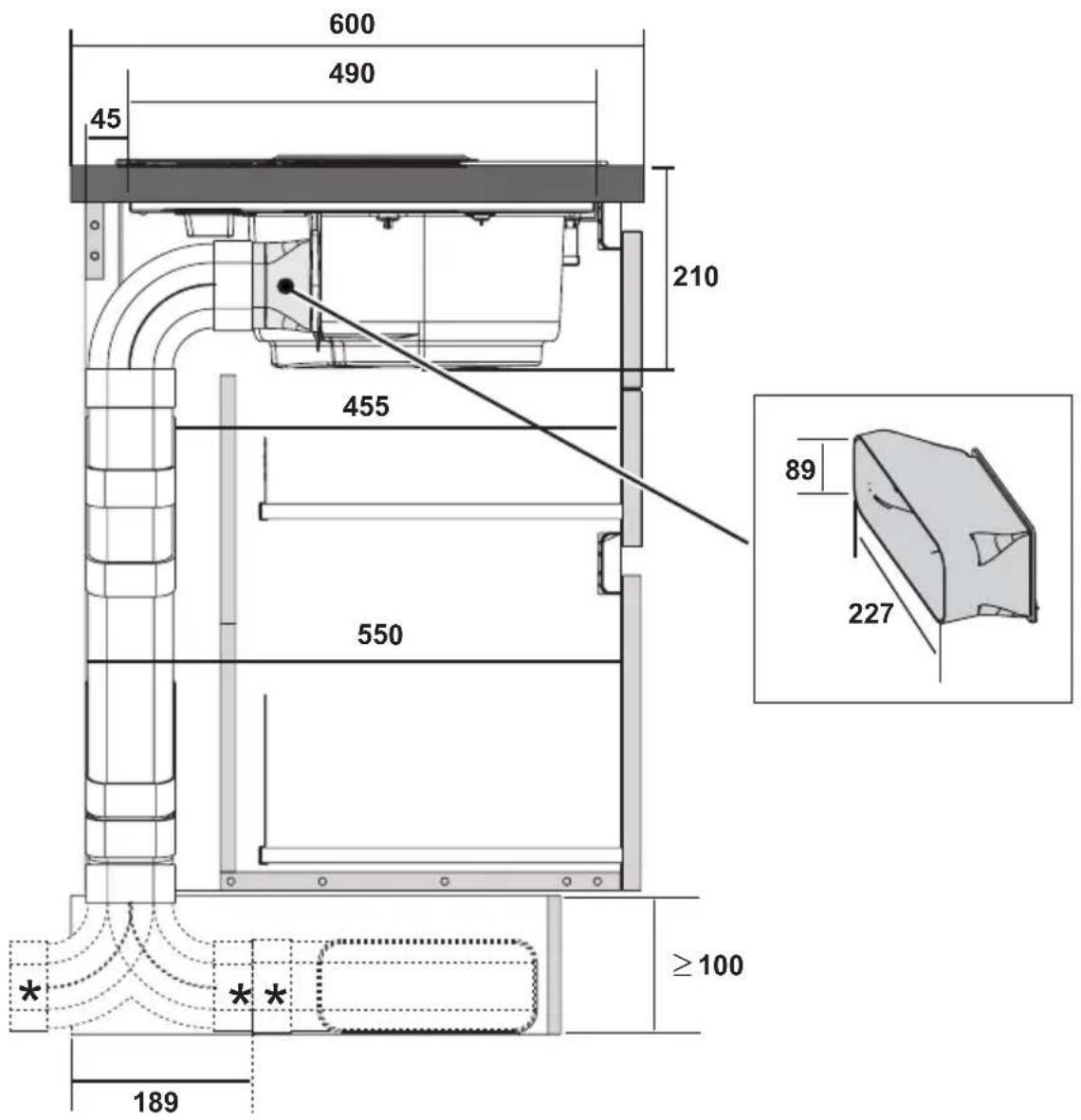
text_image
600 490 45 210 455 89 227 550 ≥100 189 * *
text_image
>600 490 210 >560 89 227 ≥100 189
natural_image
3D rendering of a transparent mechanical component with a black square top and U-shaped groove (no text or symbols visible)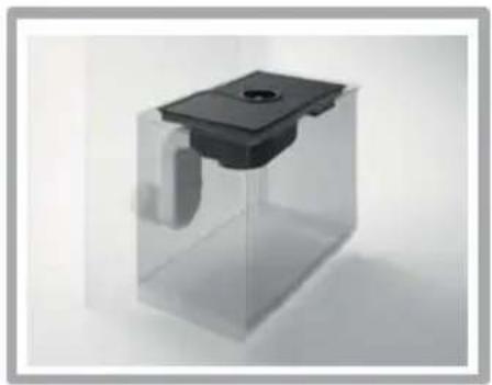
natural_image
Transparent rectangular container with a black square top and a small circular indentation on the side (no text or symbols visible)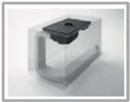
natural_image
3D rendering of a small mechanical component with a black top and U-shaped base (no text or symbols visible)KIT0121007
natural_image
Stacked 3D cubes inside a circular frame (no text or symbols)227x94 - ∅146mm
KIT0120996
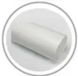
natural_image
White cylindrical object inside a gray circular border (no text or symbols)∅150x500mm
KIT0121000
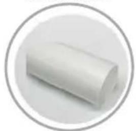
natural_image
White cylindrical object inside a gray circular border (no text or symbols)∅150x1000mm
KIT0121003
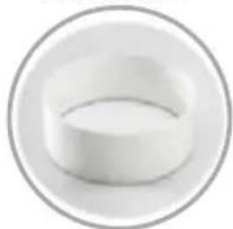
natural_image
Circular object with a white cylindrical shape, resembling a ring or container (no text or symbols visible)∅158x59mm
KIT0121006
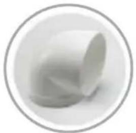
natural_image
Abstract grayscale 3D shape inside a circular frame, no text or symbols present90^
KIT0120991
natural_image
White rectangular object inside a circular frame (no text or symbols)222x89x1000mm
KIT0121001

natural_image
Simple 3D illustration of a rectangular block inside a circular frame (no text or symbols)227x94x80mm
KIT0121004
natural_image
White 3D geometric object with a curved edge, enclosed in a gray circular border (no text or symbols)90° 227x288x94mm
KIT0121005
natural_image
3D rendered white geometric object inside a gray circular border (no text or symbols)90° 227×94mm
KIT0121008
natural_image
White paper roll or cushion on a plain background, enclosed in a circular frame (no text or symbols)227x94 - ∅153mm
KIT0121010
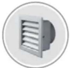
natural_image
Circular icon depicting a ventilation grille with horizontal slats, no text or symbols present.190x190 - ∅147mm
KIT0121009
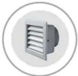
natural_image
Simple icon of a ventilation duct inside a circular frame (no text or symbols)INT 216X82mm
EXT 290X160mm
KIT0121002
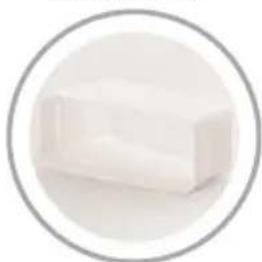
natural_image
White rectangular object inside a gray circular border (no text or symbols)15^ - 227 × 94 ~mm
KIT0126810
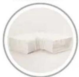
natural_image
Circular frame containing a white folded paper or document with no visible text or symbols.227x94mm

www.elica.com
www.shop.elica.com
natural_image
Simple line icon of a house with a circular arrow inside, symbolizing refresh or move (no text or symbols)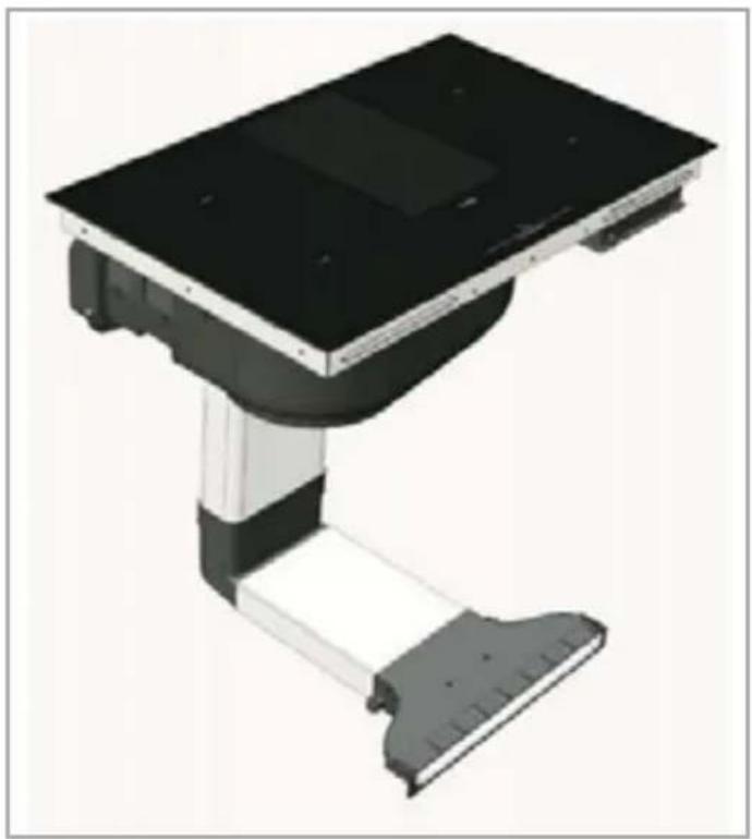
natural_image
3D rendering of a mechanical device with a black top and gray base, no visible text or symbols
text_image
6509a.1.2
natural_image
Diagram showing two views of an electronic device with a cable inserted, no text or symbols present
text_image
7009a.1.3
natural_image
Diagram showing two mechanical components with arrows indicating assembly or connection, no text or symbols present.9.2
text_image
700 650
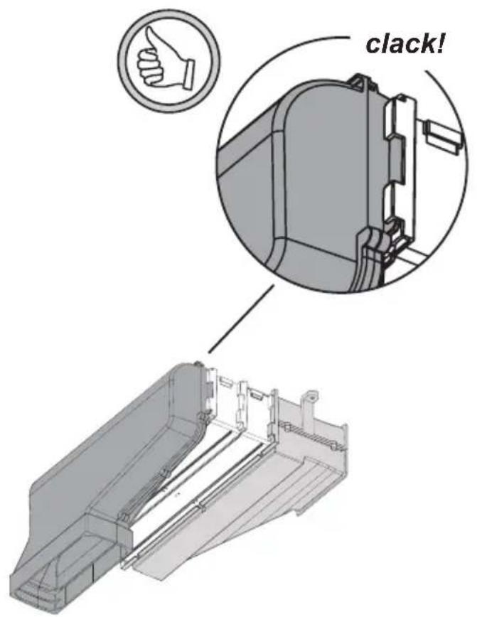
text_image
clack!9.3
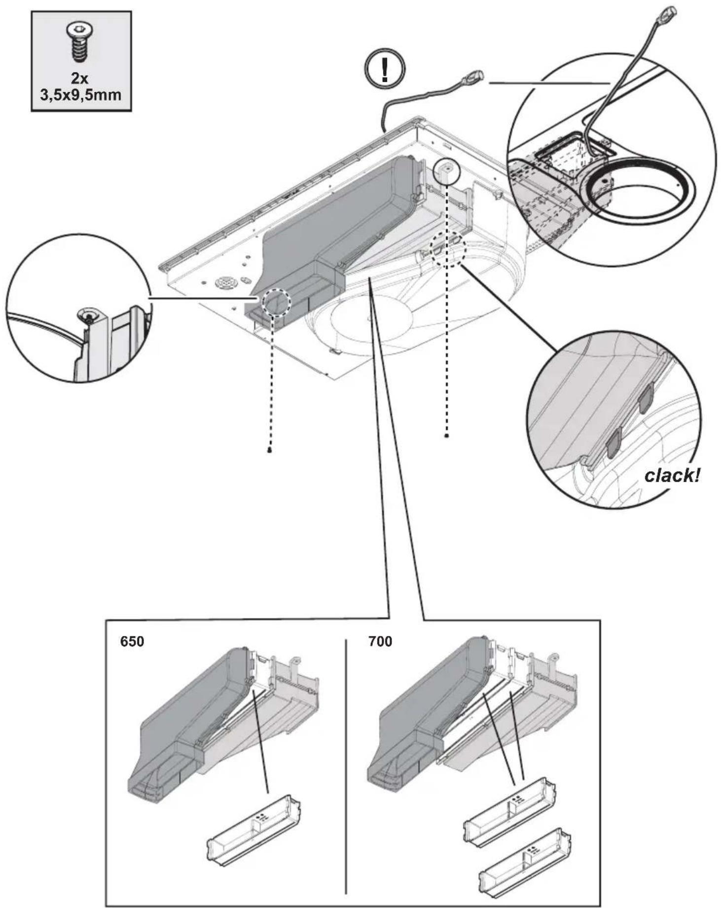
text_image
2x 3,5x9,5mm 650 700 clack!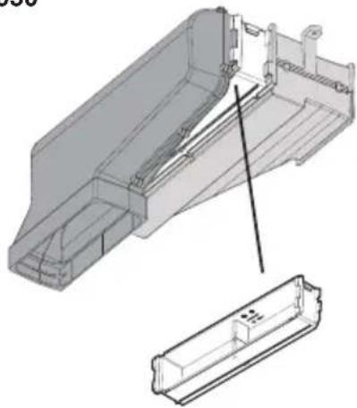
natural_image
Technical illustration of a mechanical assembly with an exploded view showing internal components (no text or symbols)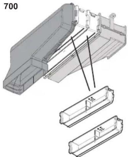
natural_image
Technical illustration of a mechanical assembly with three views (top, front, side) showing internal components and alignment lines (no text or symbols)
text_image
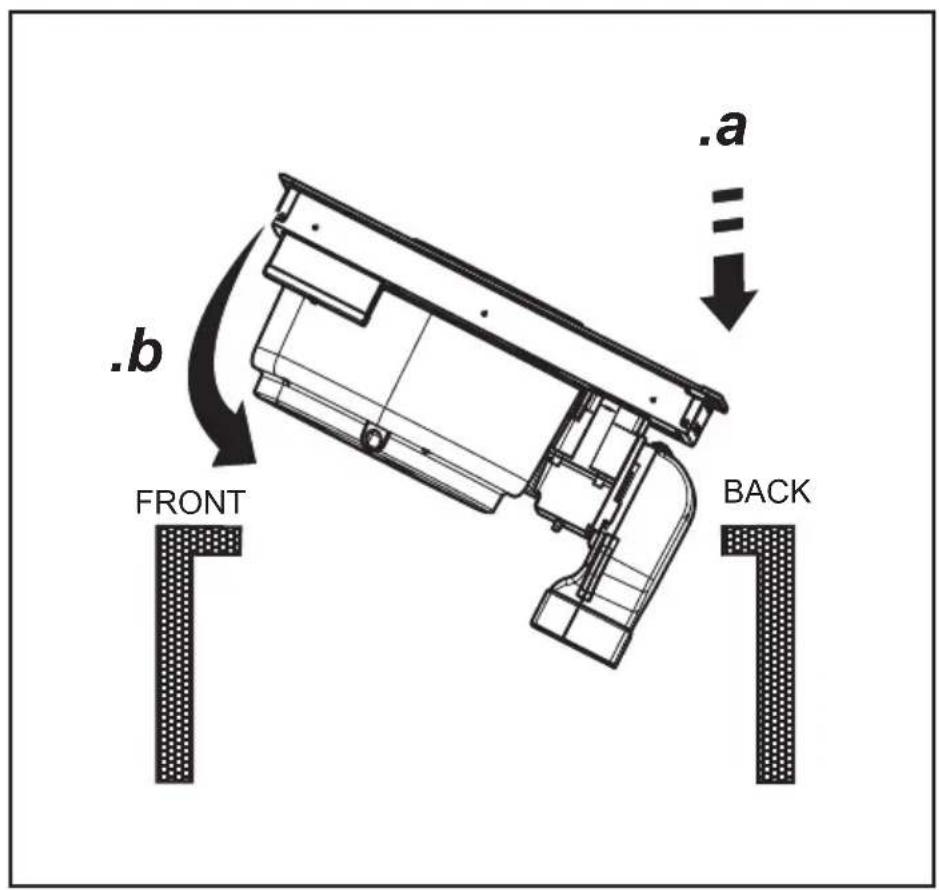
.a . b FRONT BACK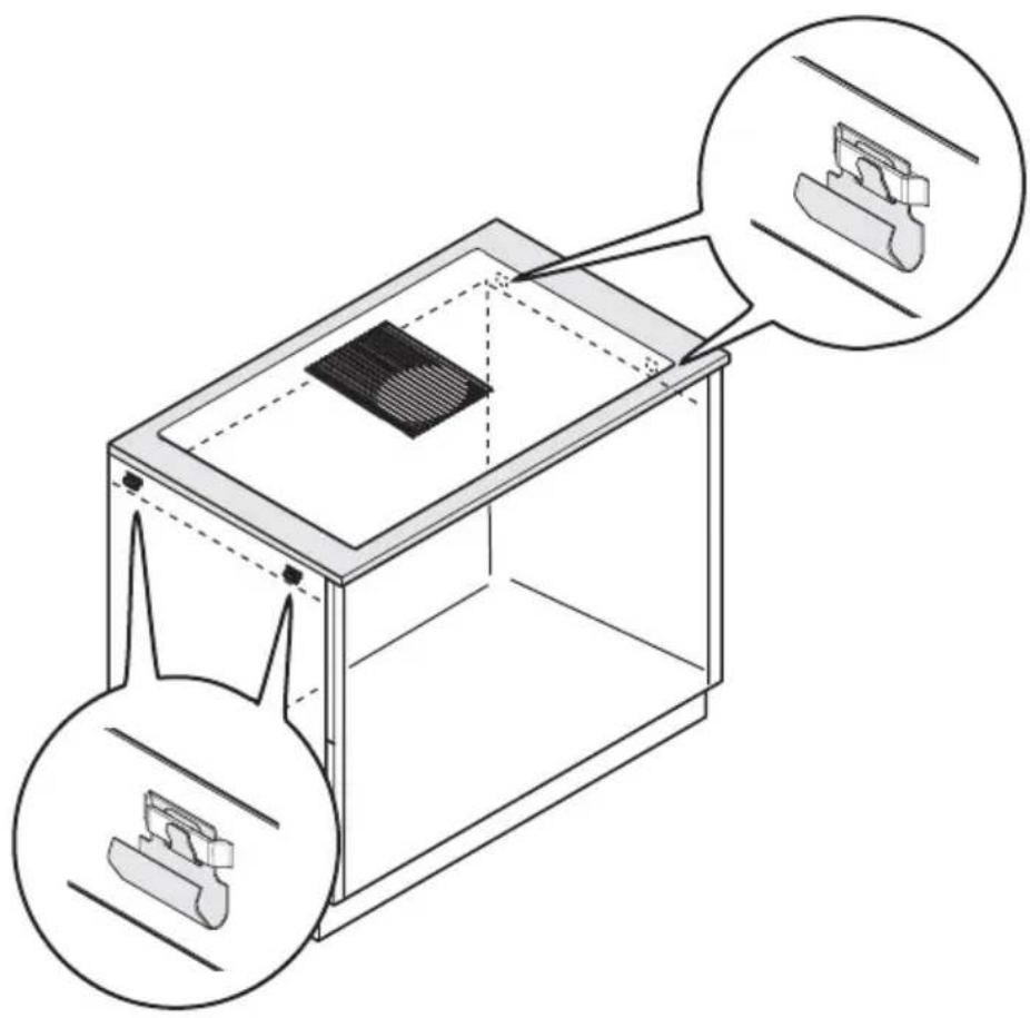
natural_image
Technical line drawing of a 3D printer or enclosure with internal components and two circular insets showing close-ups of the top and bottom views (no text or symbols present)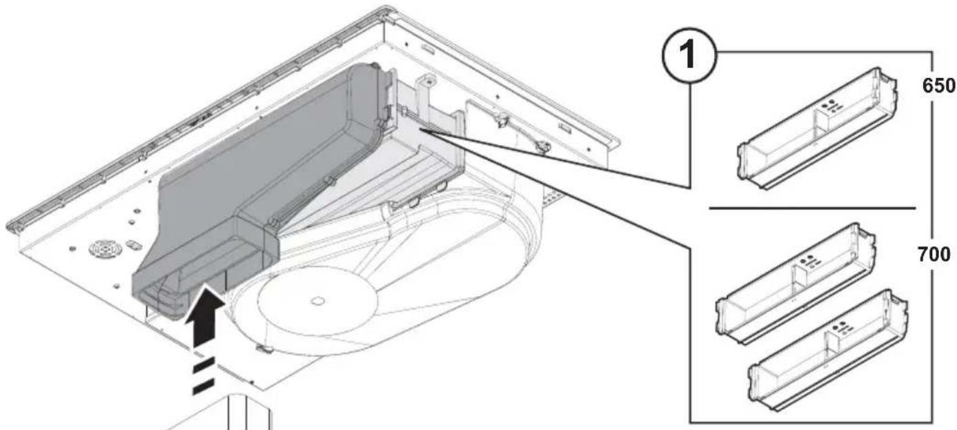
text_image
Technical diagram of an open refrigerator with labeled parts and dimensions, showing internal components and assembly steps.
natural_image
Simple line drawing of a 3D rectangular prism with an upward arrow and a double-headed arrow below (no text or symbols)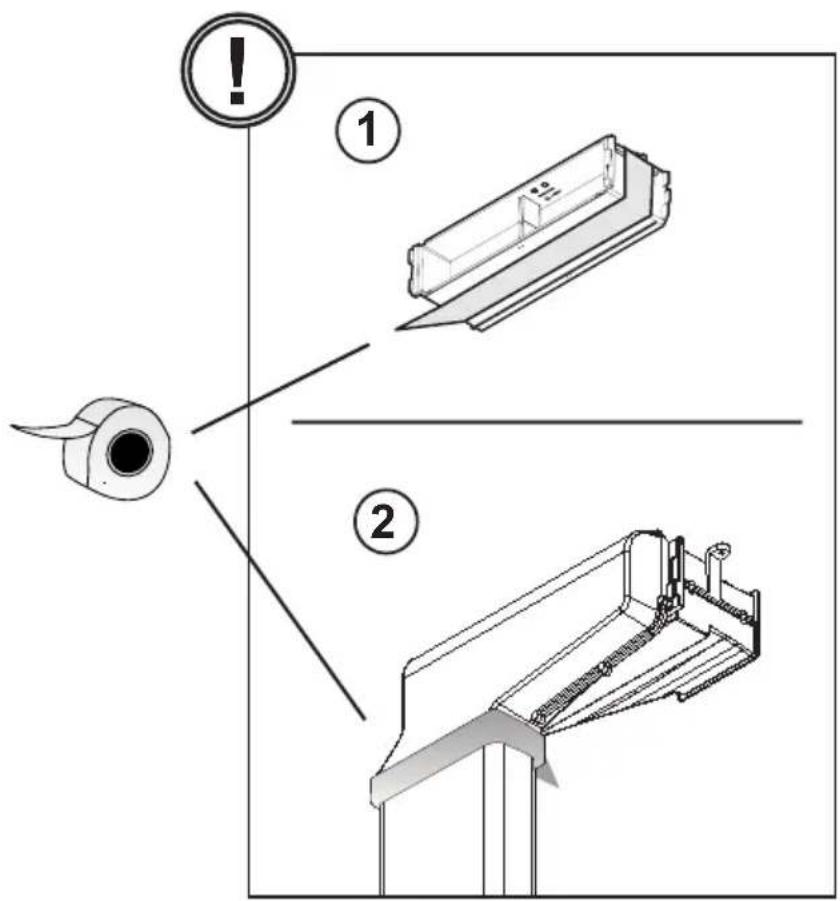
text_image
! ① ②
natural_image
Technical line drawing of a mechanical component with three views: a cylindrical part, a 3D rectangular prism, and a triangular tool (no text or symbols)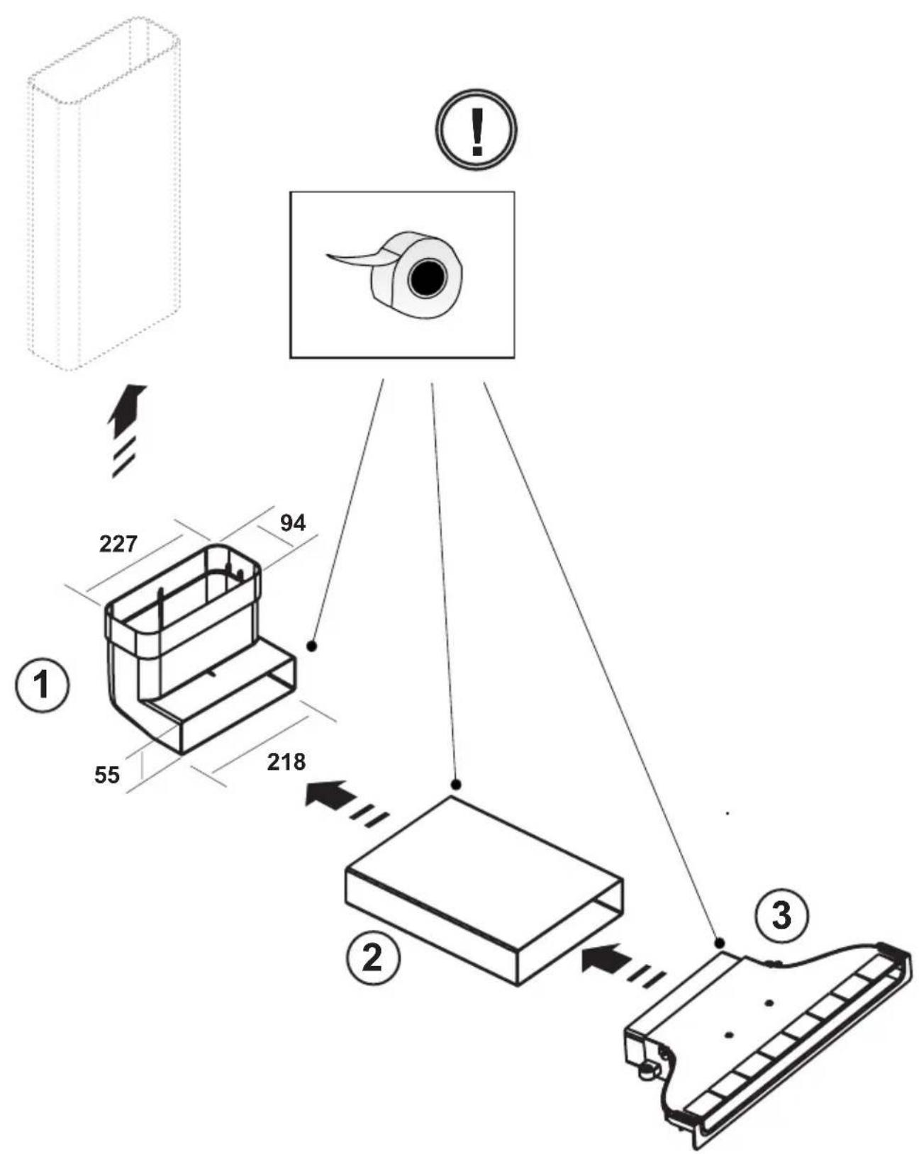
text_image
Technical diagram illustrating a device assembly with labeled components and dimensions, including a 3D box, a component, and a control panel.11.1
text_image
.a .b .c 12.112.1
text_image
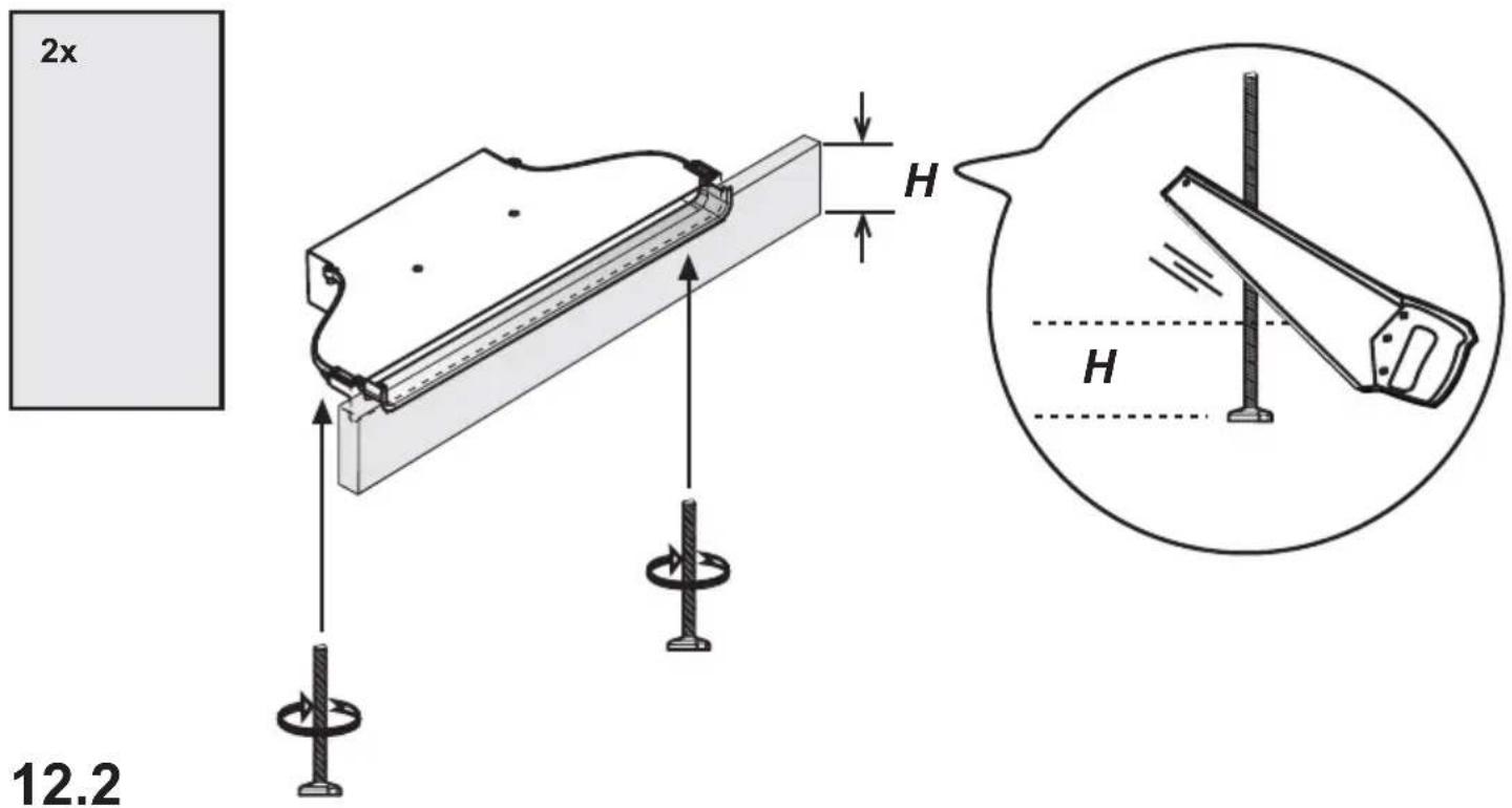
2x H H 12.2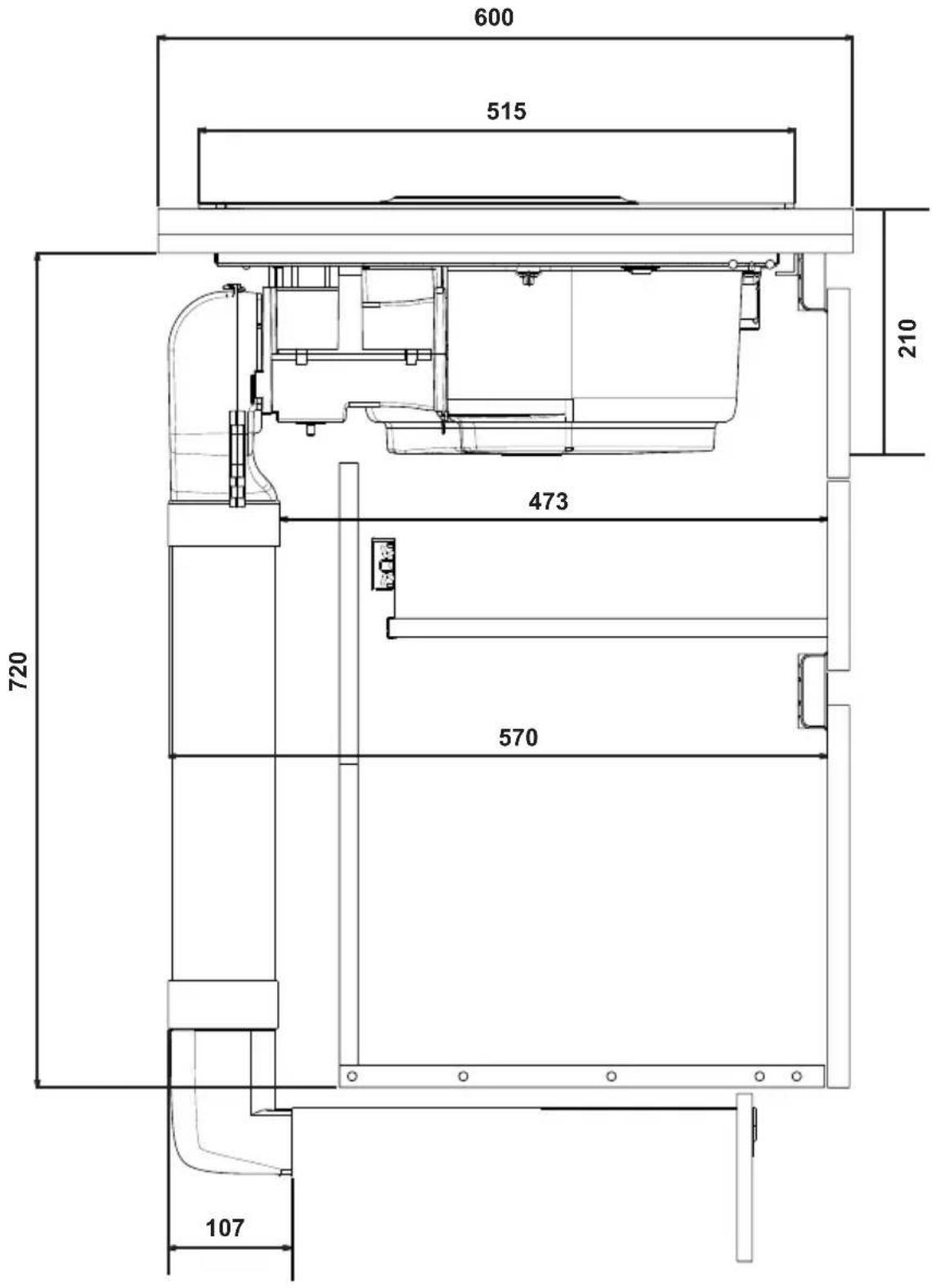
text_image
600 515 210 473 720 570 107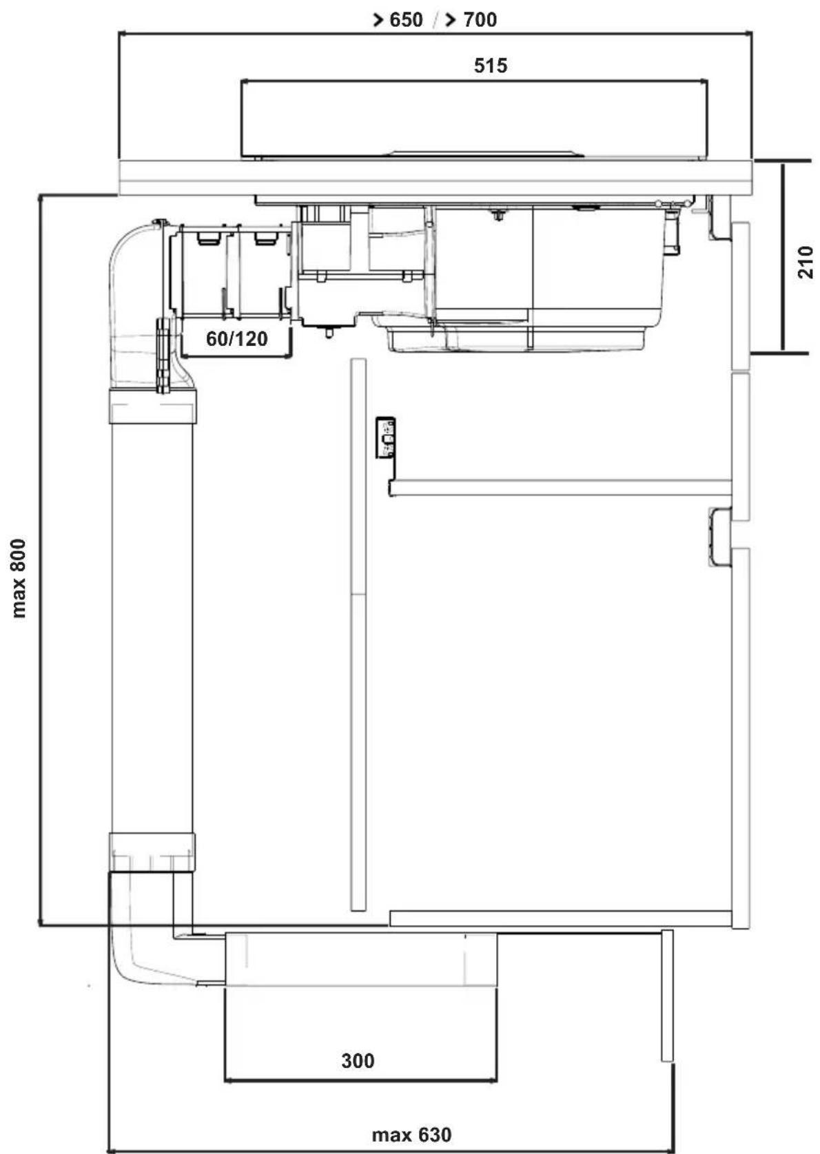
text_image
>650 / >700 515 60/120 210 max 800 300 max 630
natural_image
3D rendering of a small mechanical component with a central square and vertical supports, shown in transparent lighting (no text or symbols visible)
natural_image
3D rendering of a mechanical component with a central mounting bracket and support structure (no text or symbols visible)
natural_image
3D rendering of a mechanical device with a central mounting bracket and internal components (no visible text or symbols)
natural_image
3D rendering of a transparent cylindrical device with a square top and internal components (no text or symbols visible)
natural_image
3D rendered mechanical assembly with curved structural elements and a flat top (no text or symbols visible)KIT0121012
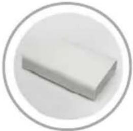
natural_image
White rectangular object inside a gray circular border (no text or symbols)218X55X500mm
KIT0121013
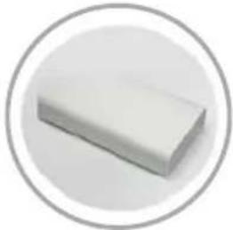
natural_image
White rectangular object with a rounded base, enclosed in a gray circular border (no text or symbols)218X55X1000mm
KIT0121015
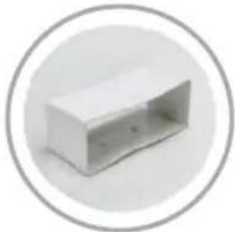
natural_image
Simple 3D rendering of a rectangular box with a hollow interior, enclosed in a circular frame (no text or symbols)218X55X70mm
KIT0121016
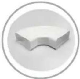
natural_image
Simple 3D-rendered white curved object inside a gray circular border (no text or symbols)90° 218X55mm
KIT0121017
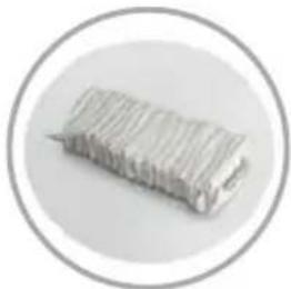
natural_image
Close-up of a cylindrical metallic object with grooved surface, enclosed in a circular frame (no text or symbols visible)218x55mm
KIT0126810
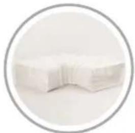
natural_image
Close-up of a white rectangular object with a curved edge, enclosed in a gray circular border (no text or symbols visible)227×94mm
KIT0121002
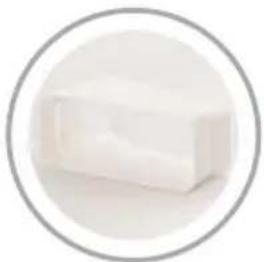
natural_image
White rectangular object inside a gray circular border (no text or symbols)15^ - 227 × 94 ~mm
KIT0121005
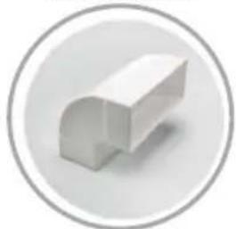
natural_image
3D rendered white geometric object inside a gray circular border (no text or symbols)90° 227x94mm
KIT0130427
natural_image
Simple line drawing of a 3D rectangular object with a folded top, enclosed in a circular border (no text or symbols)
www.elica.com
www.shop.elica.com
text_image
FIG.17 FIG.15 FIG.16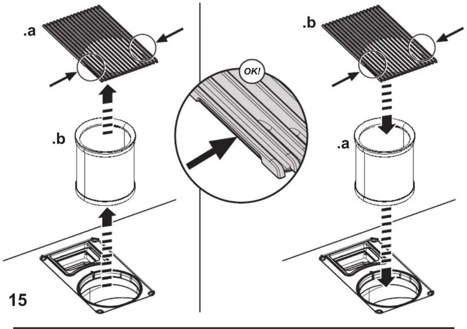
text_image
.a .b OK! . b . a 15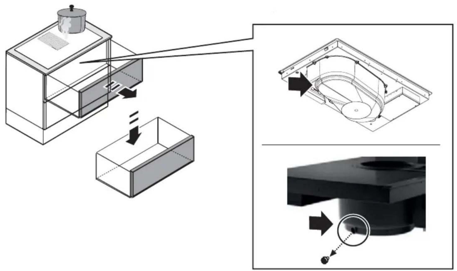
text_image
Technical diagram illustrating a mechanical assembly process with labeled components and directional arrows indicating motion or flow.
natural_image
Simple line icon of a house with a circular arrow inside, symbolizing refresh or move (no text or symbols)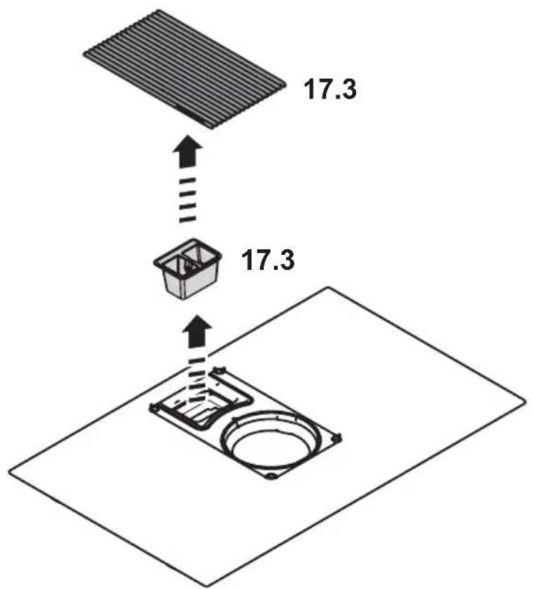
text_image
17.3 17.317
text_image
17a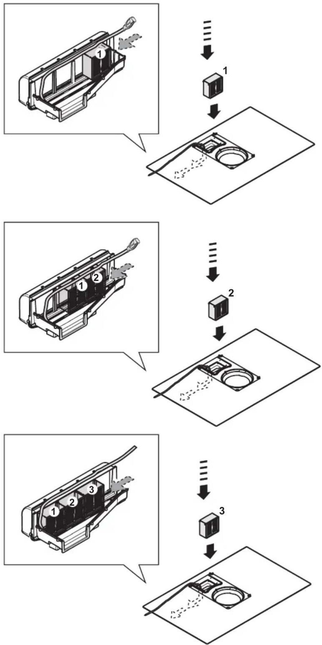
text_image
OK!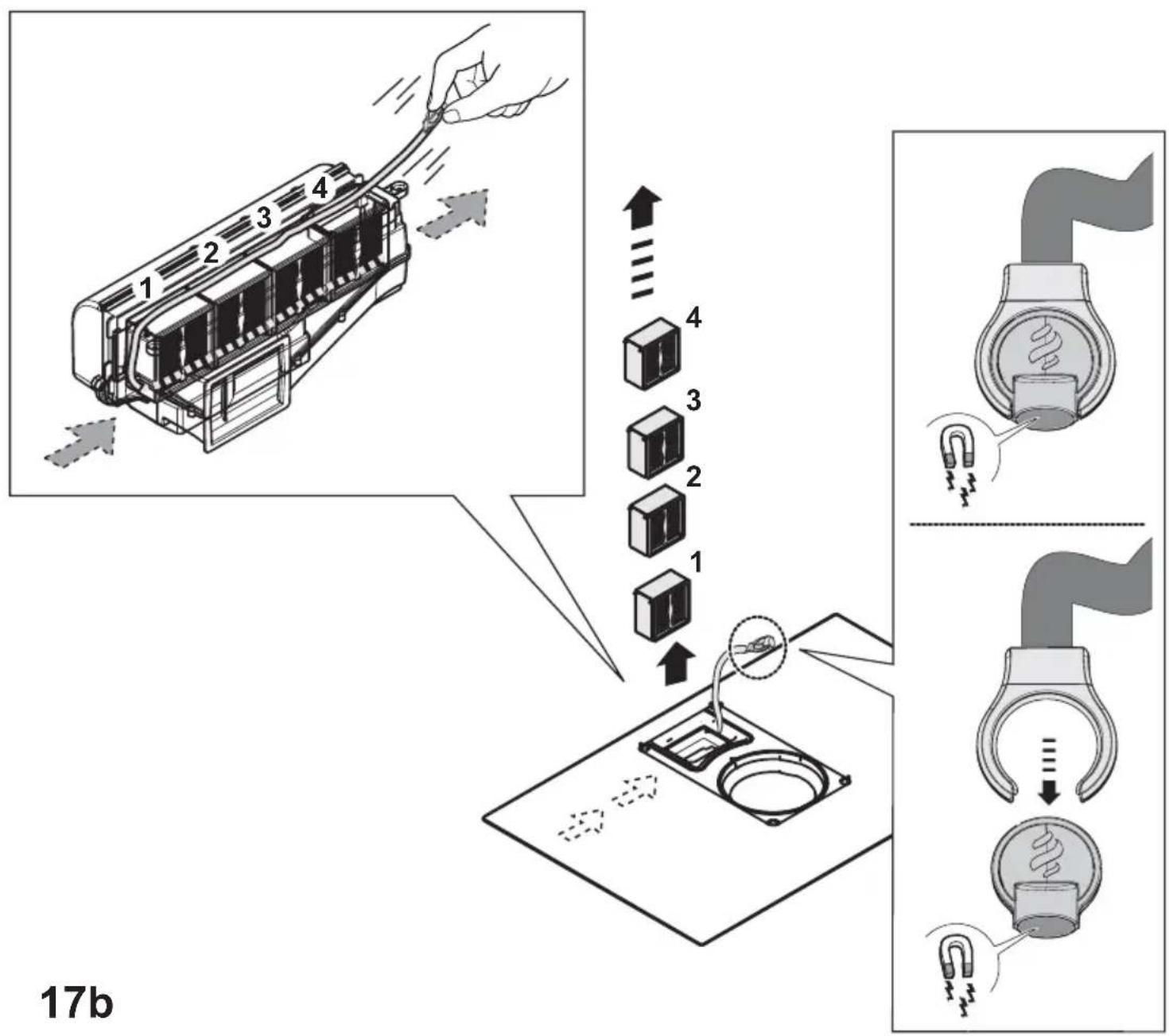
text_image
17b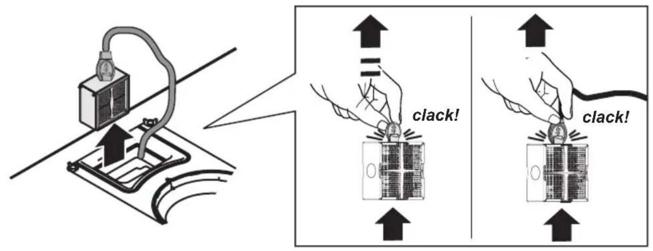
text_image
clack! clack!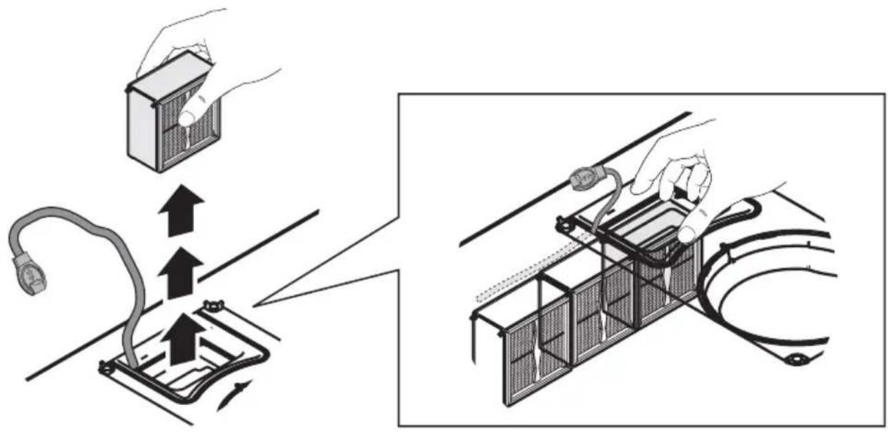
text_image
Diagram illustrating electrical installation steps with labeled components and directional arrows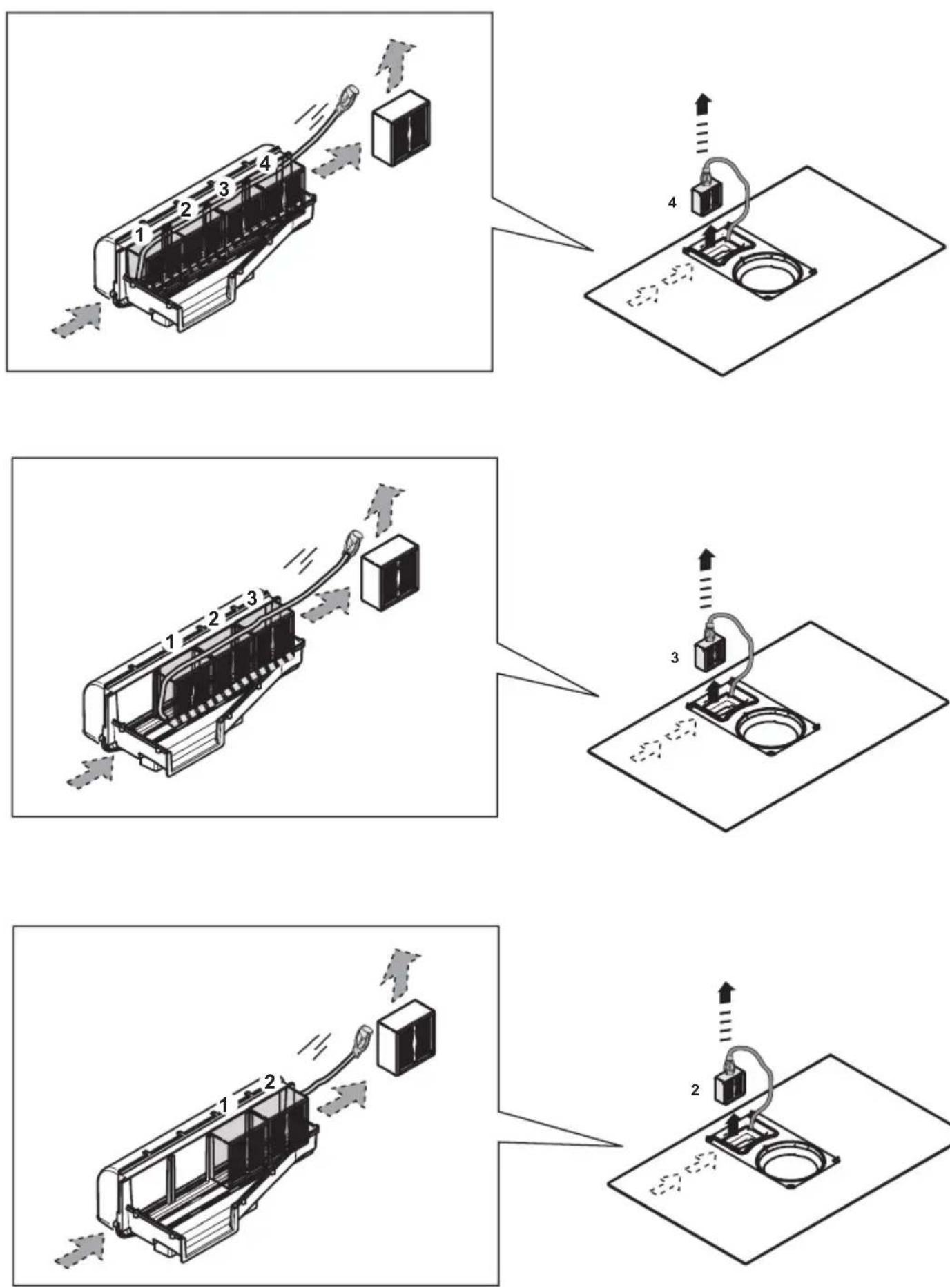
text_image
Diagram showing a device connected to a box and a sink, with labeled components and directional arrows indicating process flow.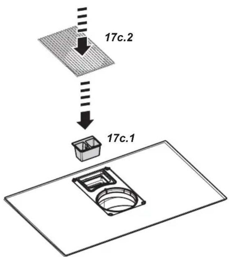
text_image
17c.2 17c.1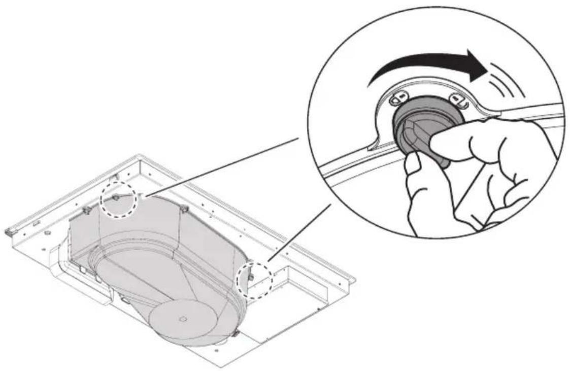
text_image
Technical diagram showing a mechanical component being turned into a circular button, with an inset illustrating the motion of the turning process.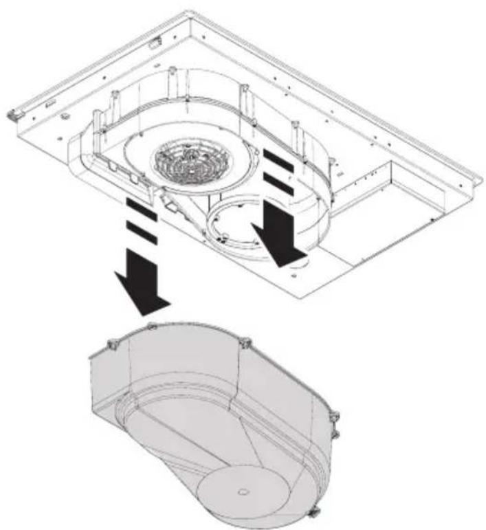
natural_image
Technical diagram showing a mechanical assembly with internal components and directional arrows (no text or symbols)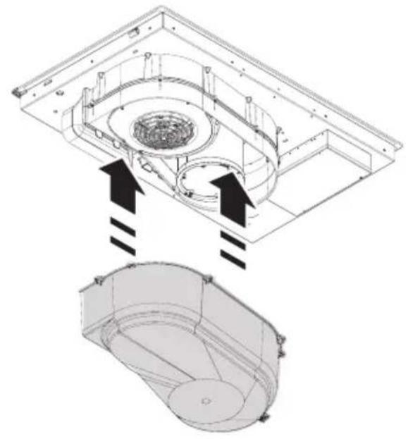
natural_image
Technical diagram showing a mechanical assembly with two views of a housing or enclosure, no text or symbols present.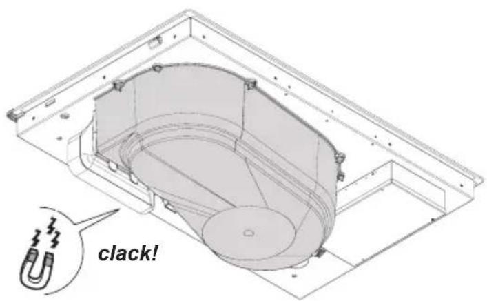
text_image
clack!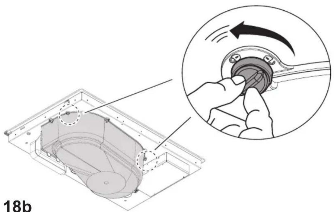
text_image
18b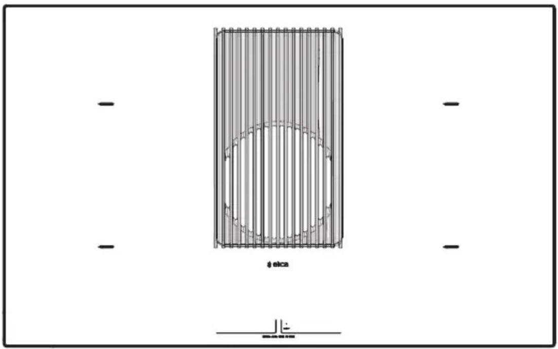
text_image
ø elca2
text_image
2,3 - 3 kw Ø 120mm Ø 200mm3
text_image
2,3 - 3 kw Ø 120mm Ø 200mm1
text_image
1,2 - 1,4 kw Ø 110mm Ø 160mm4
text_image
1,2 - 1,4 kw Ø 110mm Ø 160mm
text_image
OK! OK!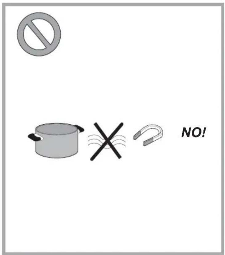
text_image
NO!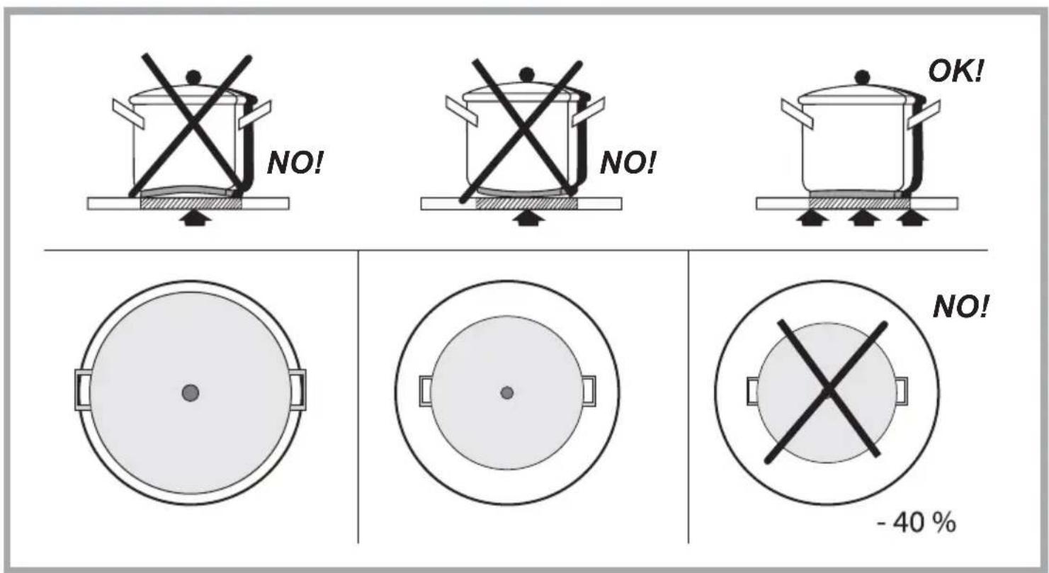
text_image
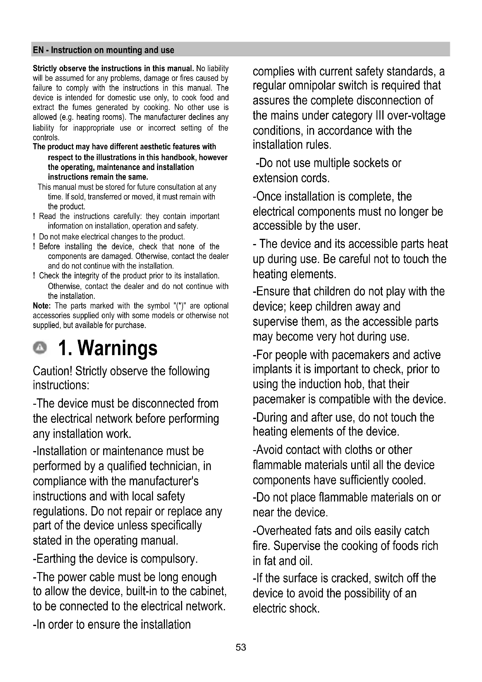
NO! NO! OK! NO! - 40 %Strictly observe the instructions in this manual. No liability will be assumed for any problems, damage or fires caused by failure to comply with the instructions in this manual. The device is intended for domestic use only, to cook food and extract the fumes generated by cooking. No other use is allowed (e.g. heating rooms). The manufacturer declines any liability for inappropriate use or incorrect setting of the controls.
The product may have different aesthetic features with respect to the illustrations in this handbook, however the operating, maintenance and installation instructions remain the same.
This manual must be stored for future consultation at any time. If sold, transferred or moved, it must remain with the product.
! Read the instructions carefully: they contain important information on installation, operation and safety.
! Do not make electrical changes to the product.
! Before installing the device, check that none of the components are damaged. Otherwise, contact the dealer and do not continue with the installation.
! Check the integrity of the product prior to its installation.
Otherwise, contact the dealer and do not continue with the installation.
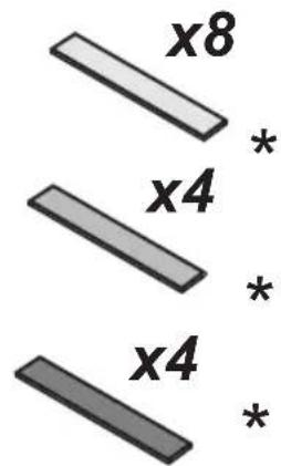
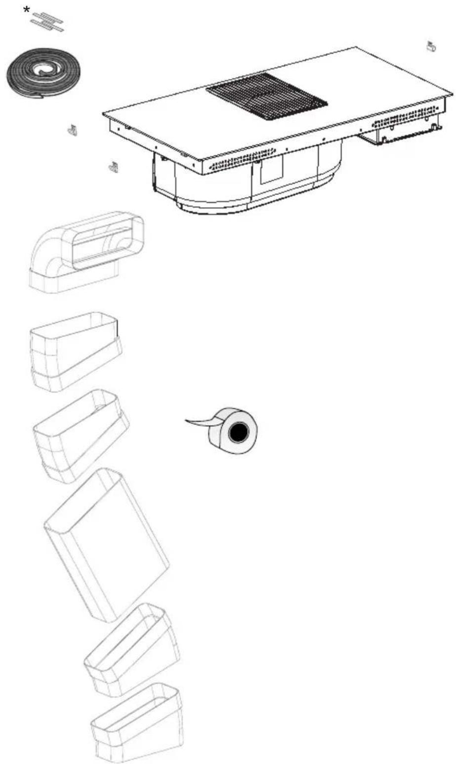
Note: The parts marked with the symbol "(*)" are optional accessories supplied only with some models or otherwise not supplied, but available for purchase.

1. Warnings
Caution! Strictly observe the following instructions:
-The device must be disconnected from the electrical network before performing any installation work.
-Installation or maintenance must be performed by a qualified technician, in compliance with the manufacturer's instructions and with local safety regulations. Do not repair or replace any part of the device unless specifically stated in the operating manual.
-Earthing the device is compulsory.
-The power cable must be long enough to allow the device, built-in to the cabinet, to be connected to the electrical network.
-In order to ensure the installation
complies with current safety standards, a regular omnipolar switch is required that assures the complete disconnection of the mains under category III over-voltage conditions, in accordance with the installation rules.
- Do not use multiple sockets or extension cords.
-Once installation is complete, the electrical components must no longer be accessible by the user. - The device and its accessible parts heat up during use. Be careful not to touch the heating elements.
-Ensure that children do not play with the device; keep children away and supervise them, as the accessible parts may become very hot during use.
-For people with pacemakers and active implants it is important to check, prior to using the induction hob, that their pacemaker is compatible with the device.
-During and after use, do not touch the heating elements of the device.
-Avoid contact with cloths or other flammable materials until all the device components have sufficiently cooled.
-Do not place flammable materials on or near the device.
-Overheated fats and oils easily catch fire. Supervise the cooking of foods rich in fat and oil.
-If the surface is cracked, switch off the device to avoid the possibility of an electric shock.
-The device is not intended to be run with an external timer or a separate remote control system.
-Unattended cooking on a hob with oil or fat may be dangerous and may cause a fire.
- The cooking process must be supervised. A short-term cooking process must be constantly monitored.
- NEVER attempt to put fires out using water. Instead, turn off the device and smother the flames, for example with a lid or a fire blanket. Fire hazard: do not rest objects on the cooking surfaces.
-Do not use steam cleaners.
-Do not place metal objects such as knives, forks, spoons and lids on the hob surface as they may overheat.
- Before connecting the device to the electrical network: check the data plate (on the bottom of the device) to ensure that the voltage and power correspond to the network values and that the connection socket is suitable. If in doubt, consult a qualified electrician.
Important:
- After use, switch off the hob from its control device and do not rely on the pot detector.
-Avoid spills; when boiling or heating liquids, lower the heat supply.
- Do not leave the heating elements on with pots and pans empty or without containers.
- Once cooking is complete, turn off the relative zone.
- Never use aluminium foil to cook with, and never directly place products packaged with aluminium on top of the cooking surface. The aluminium would melt and irreparably damage your device.
- Never heat a tin or a tin can containing foods without first opening it: it might explode!
This warning also applies to all other types of hobs.
- A high power level such as the Booster function should not be used to heat certain liquids such as oil for frying.
Excessive heat may be dangerous. In these cases we recommend the use of a lower power level.
-The containers must be placed directly on the hob and should be centred. Under no circumstances may anything be inserted between the pot and the hob.
- In high temperature situations, the device automatically decreases the power level of the cooking zones.
Before performing any cleaning or maintenance, disconnect the product from the electrical network by detaching the plug or disconnecting the home's master switch.
For all installation and maintenance operations, always use work gloves.
The device can be used by children 8 years or older and by persons with physical, sensory or mental impairments, or by people without any experience or the necessary knowledge, provided they are supervised or have received
instructions regarding the safe use of the device and provided they have a thorough understanding of the associated risks.
Children must be supervised to ensure they do not play with the device.
Cleaning and maintenance must never be performed by children unless they are properly supervised.
The room must be properly ventilated when the cooker hood is used at the same time as other combustion devices, gas or otherwise.
The hood must be regularly cleaned both internally and externally (AT LEAST ONCE PER MONTH), in strict accordance with the maintenance instructions.
Failure to follow the rules for hood cleaning and filter replacement and cleaning shall result in a fire hazard.
It is strictly prohibited to flame food.
The use of an open flame may damage the filters and cause a fire hazard; it must therefore be avoided under all circumstances.
Extra care must be taken when frying to prevent the oil from overheating and catching fire.
CAUTION: When the hob is on, the accessible parts of the hood may become hot.
Caution! Do not connect the device to the electrical network until installation is entirely complete.
In regards to the technical and safety measures that must be adopted for fume extraction, regulations issued by local authorities must be strictly followed.
The extracted air must not be conveyed through the same ducts used to extract the fumes generated by gas combustion or other types of combustion devices.
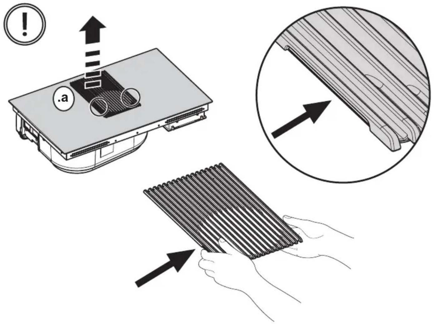
Never use the hood unless the grill has been correctly assembled!
Use only the fastening screws supplied with the product for its installation, or if not supplied, purchase the correct type of screws. Use screws with the right length, as indicated in the installation guide.
When the cooker hood is used together with other devices powered with non-electrical energy, the negative pressure of the room must not exceed 4 Pa (4 x 10⁻⁵ bar).
This device is marked in compliance with the European Directive 2002/96/EC, Waste Electrical and Electronic Equipment (WEEE). By ensuring that this product is disposed of correctly, the user will help prevent potential negative consequences for the environment and human health.
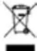
The symbol ■ on the product or accompanying documentation indicates that this product should not be treated as household waste but should be handed over at a suitable collection point for the recycling of electrical and electronic equipment. Dispose of the device in accordance with local regulations on waste disposal. For further information about the treatment, recovery and recycling of this product, please contact your local authority, a collection service for household waste or the shop where the product was purchased.
Device designed, tested and developed in compliance with regulations on:
- Safety: EN/IEC 60335-1; EN/IEC 60335-2-6, EN/IEC 60335-2-31, EN/IEC 62233.
• Performance: EN/IEC 61591; ISO 5167-1; ISO 5167-3; ISO 5168; EN/IEC 60704-1; EN/IEC 60704-2-13; EN/IEC 60704-3; ISO 3741; EN 50564; IEC 62301.
- EMC: EN 55014-1; CISPR 14-1; EN 55014-2; CISPR 14-2; EN/IEC 61000-3-3; EN/IEC 61000-3-12. Recommendations for correct use in order to reduce the impact on the environment: When starting to cook, turn on the hood at minimum speed and leave it on for a few minutes even after cooking is complete. Increase the speed only if there is a large
amount of fumes and steam, using the Booster function only in extreme cases. To keep the odour reduction system running efficiently, replace the carbon filter/s when necessary. To ensure the high performance of the grease filter, clean it when necessary. To improve efficiency and minimise noise, use the maximum ducting diameter indicated in this manual.
2. Use
Using the hob
The induction cooking system is based on the physical phenomenon of magnetic induction. The main characteristic of this system is the direct transfer of energy from the generator to the pot.
Advantages:
When compared to electric hobs, your induction hob is:
- Safer: lower temperature on the glass surface.
- Faster: shorter food heating times.
- More accurate: the hob immediately reacts to your commands
- More efficient: 90% of the absorbed energy is transformed into heat. Moreover, once the pot is removed from the hob, heat transmission is immediately interrupted, avoiding unnecessary heat losses.
2.1 Cooking containers

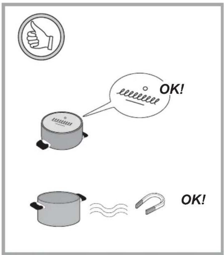
Use only pots bearing the symbol Important:
to avoid permanent damage to the hob surface, do not use:
- containers with less than perfectly flat bottoms.
- metal containers with enamelled bottoms.
- containers with a rough base, to avoid scratching the hob surface.
- never place hot pots and pans on the surface of the hob's control panel
2.1.1 Pre-existing containers
Induction cooking uses magnetism to generate heat. Containers must therefore contain iron. Check if the pot material is magnetic using a magnet. Pots are not suitable if they are not magnetically detectable.
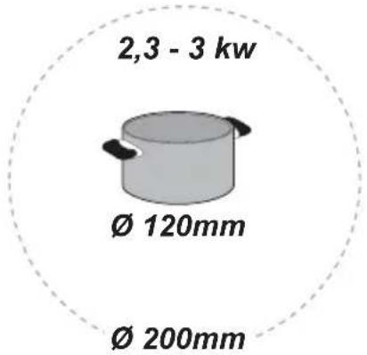
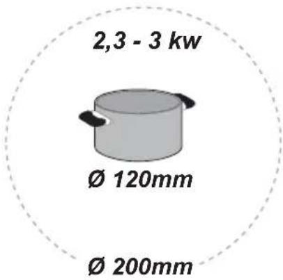
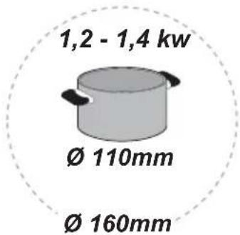
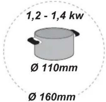
2.1.2 Recommended pan bottom diameters
IMPORTANT: if the pots are not correctly sized, the cooking zones will not turn on
For details of the minimum pot diameter that needs to be used on each zone, see the illustrated part of this manual.
2.2 Energy saving
Recommendations for best results:
- Use pots and pans with a bottom diameter equal to that of the cooking zone.
- Use only pots and pans with flat bottoms.
- Where possible, keep the lid on pots during cooking
- Cook vegetables, potatoes, etc. with a small amount of water to reduce cooking time.
- Use a pressure cooker, it further reduces the energy consumption and cooking time
- Place the pot in the centre of the cooking zone drawn on the hob.
Using the extractor fan
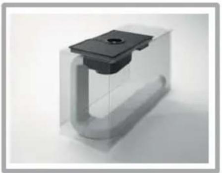
The extraction system can be used in two versions: external extraction and evacuation or as a filter with internal recirculation.

Extraction version
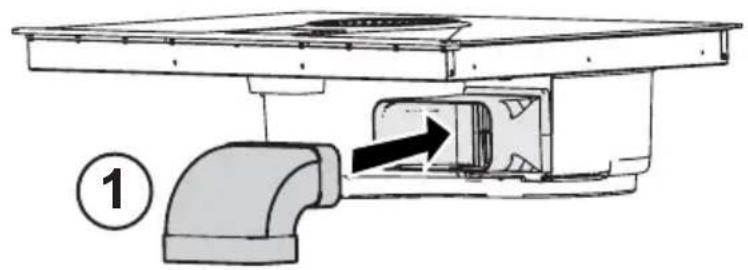
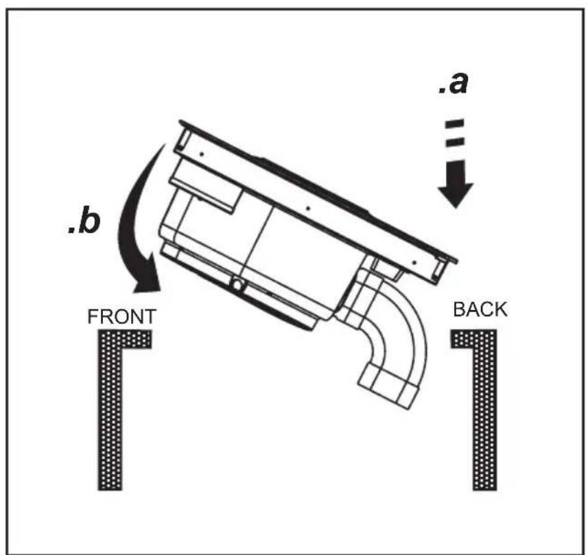
Fig.7
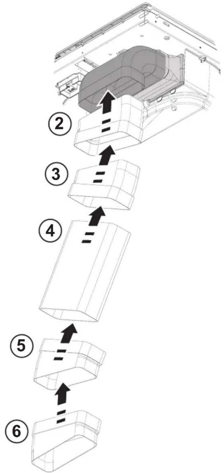
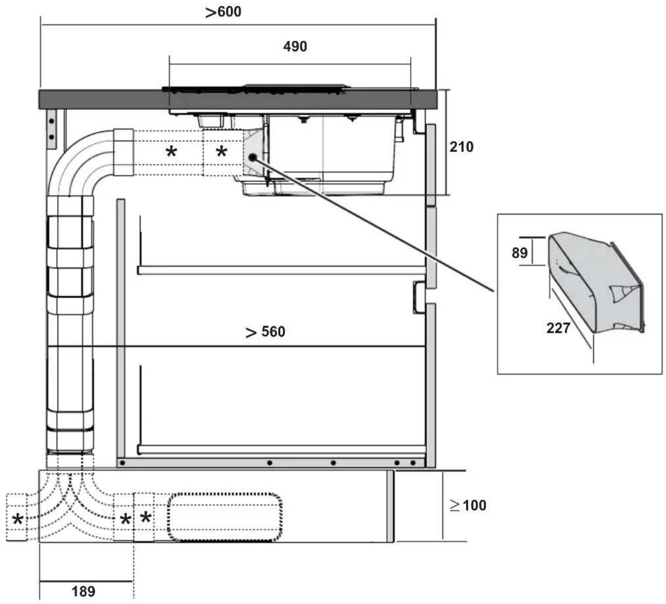
The fumes are evacuated towards the outside through a series of pipes (bought separately) fastened to the supplied connecting flange.
The diameter of the exhaust pipe must be equivalent to the diameter of the connecting ring:
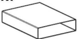
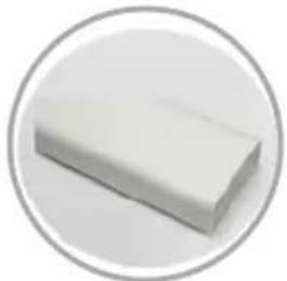
- for rectangular outlets 222 x 89 mm
- for circular outlets ∅ 150 mm (*)
For more information, see the page relative to the extraction version in the illustrated part of this manual.
Fig.7c
Connect the product to wall-mounted exhaust pipes and holes with a diameter equivalent to the air outlet (connecting flange). Using wall-mounted exhaust pipes and holes with a smaller diameter may reduce the efficiency of extraction and drastically increase noise levels.
All responsibility in this regard is therefore denied.
! Use ducting with the minimal indispensable length.
! Use ducting with the least possible number of curves (maximum angle: 90°).
! Avoid drastic changes in the ducting diameter.

Filtration version
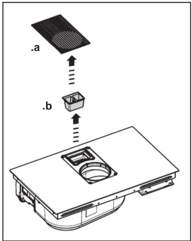
Fig. 8
The extracted air will be filtered in special grease filters and odour filters before being sent back into the room.
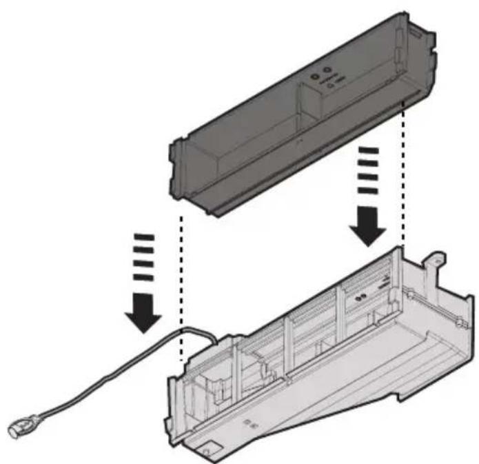
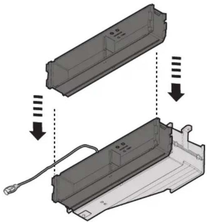
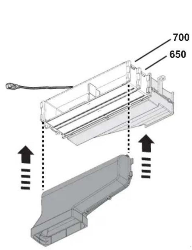
The product is supplied with all parts necessary for standard installation, with the air outlet positioned in the front part of the cabinet plinth.
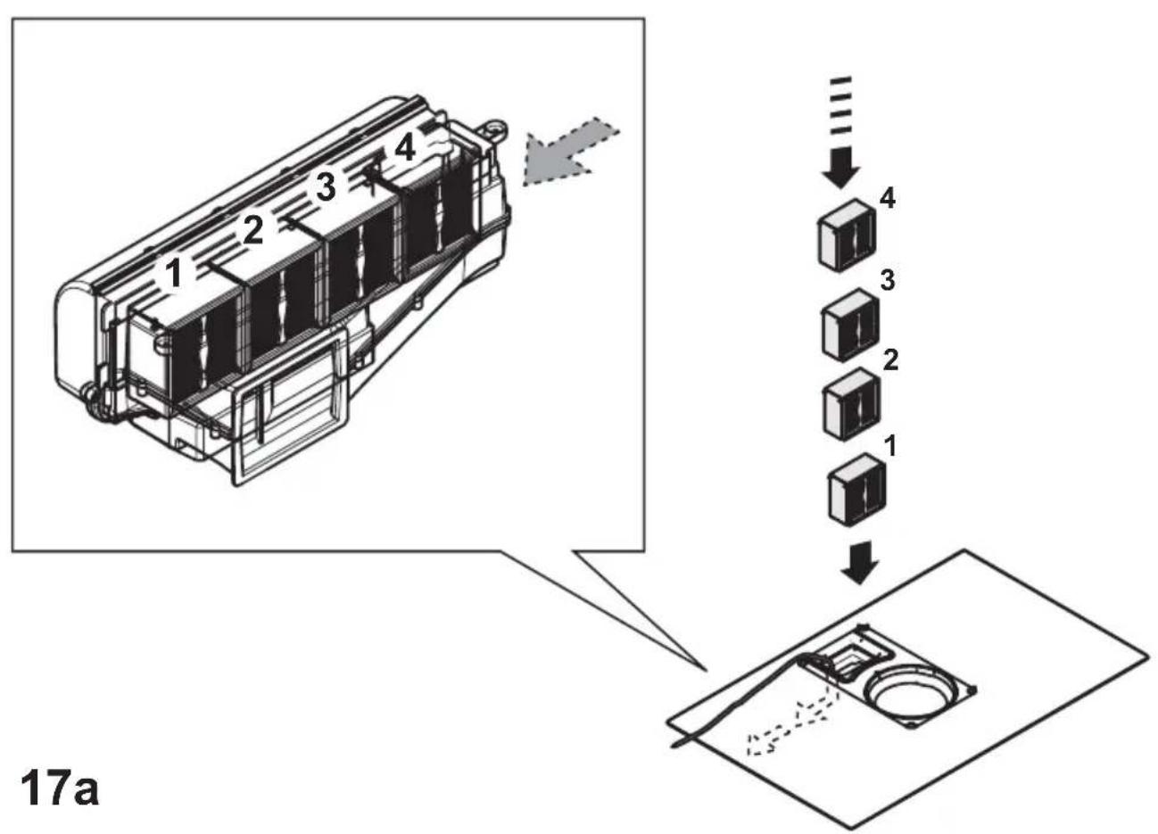
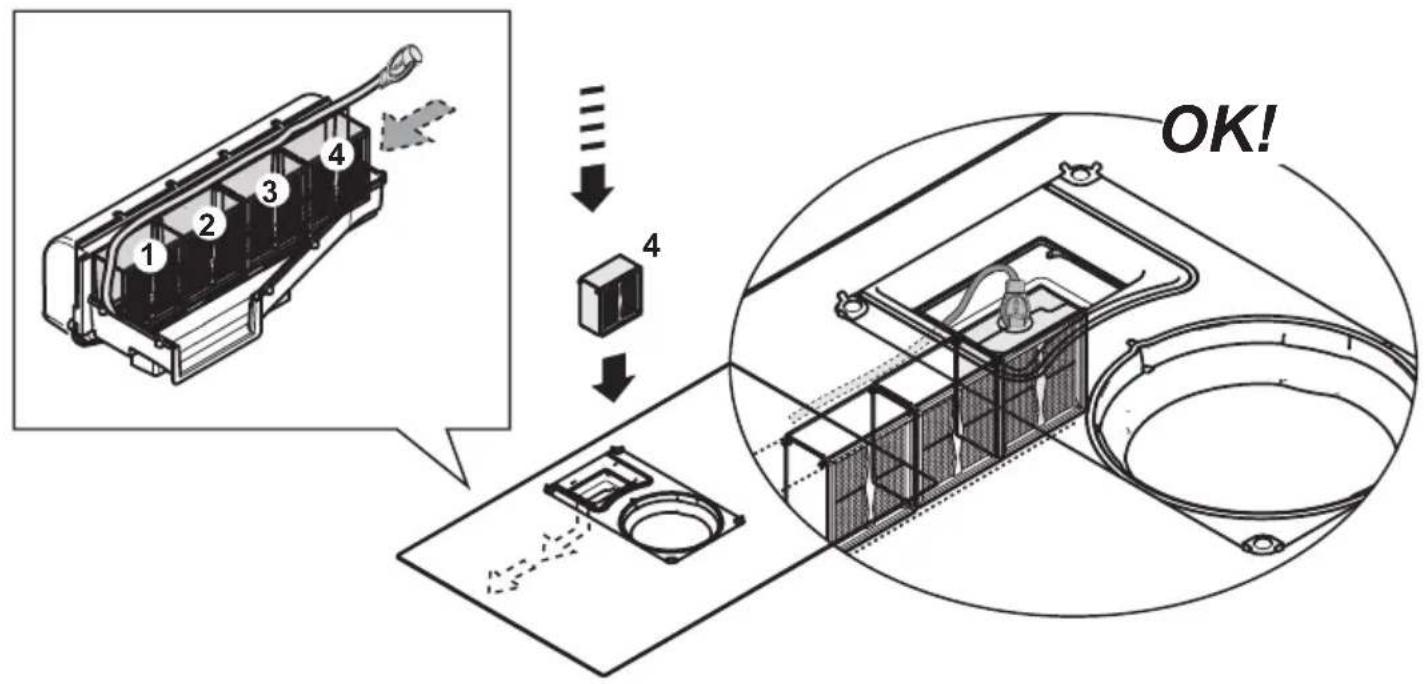
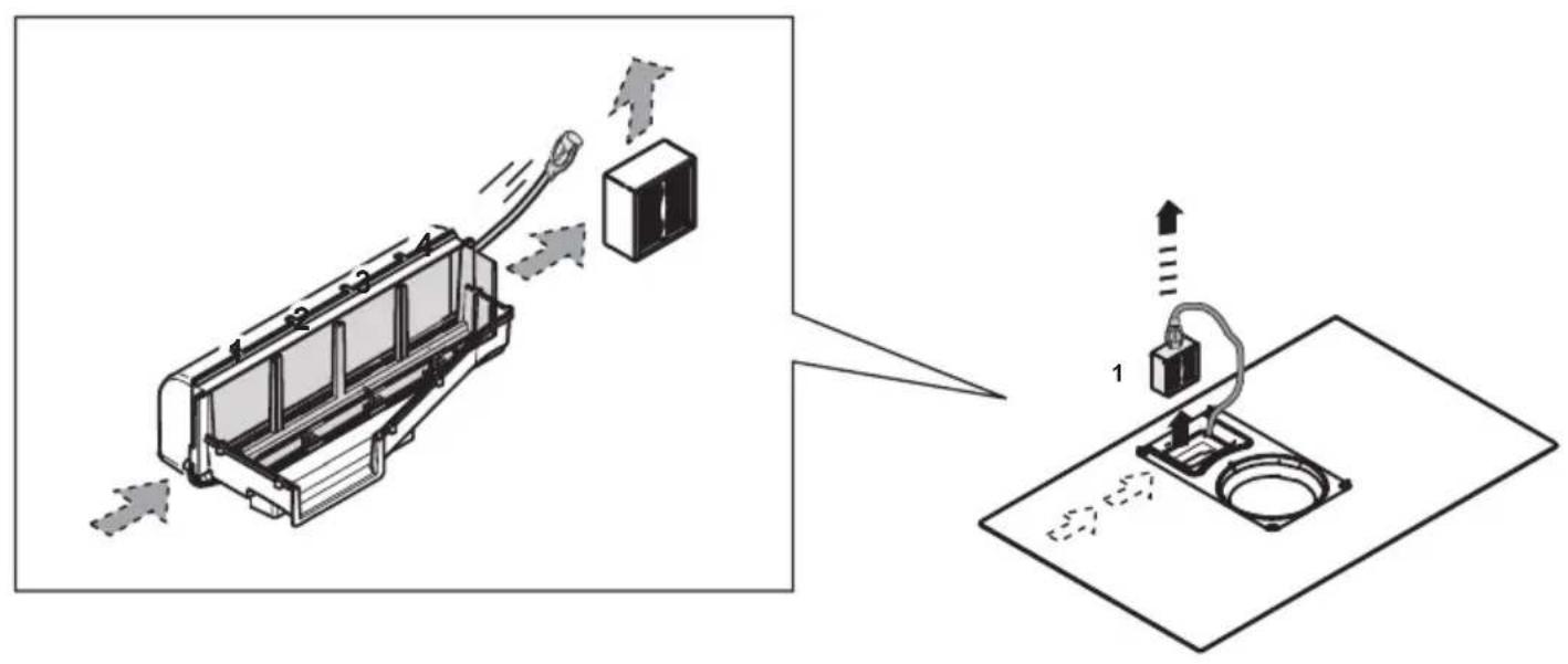
Four high-performance ceramic activated carbon filter packs are already supplied with the product. Ceramic filters are innovative modular carbon filters, which are regenerating (see the Maintenance - Activated carbon filters section of this manual).
Their chemical-physical properties allow extremely efficient odour absorption and high mechanical resistance.
For more information, see the page relative to the filtration version (in the illustrated part of this manual).
Fig. 13b
Visit the websites www.elica.com and www.shop.elica.com to check the complete range of available kits for different types of filtration and extraction installations.
3. Installation
The electrical and mechanical installation must be performed by qualified personnel.
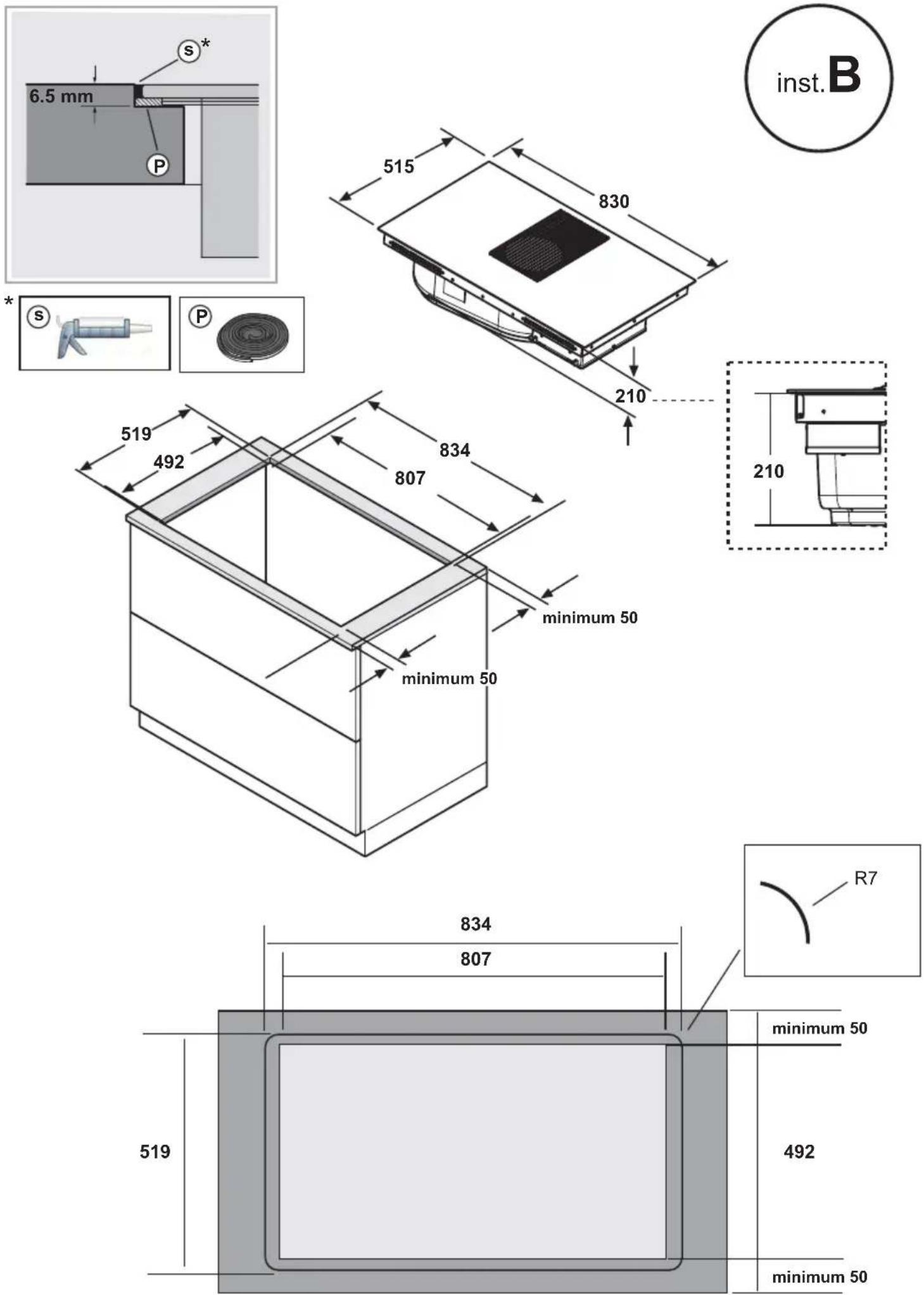
The electrical appliance is designed to be built-in to a 2-6 cm thick worktop in the case of TOP installations; 2.5-6 cm in the case of FLUSH installations.
The minimum clearance between the cooktop and wall must be at least 5 cm at the front, at least 4 cm on the side and at least 50 cm with respect to the wall units above.
NB = The suggested clearances are indicative: when designing the spaces, follow the instructions of the kitchen manufacturer.

3.1 Electrical connection
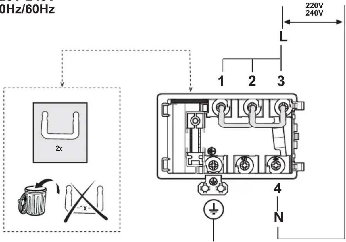
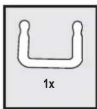
Fig. 3
- Disconnect the device from the electrical network
-The installation must be performed by professionally qualified personnel familiar with the applicable installation and safety standards.
-The manufacturer declines any liability to people, animals or things in the case of failure to follow the guidelines provided in this chapter.
-The power cable must be long enough to allow removal of the hob from the worktop
-Make sure that the voltage on the rating plate on the bottom of the device corresponds to that of the house where it will be installed.
-Do not use extension cords.
- Earthing is required by law
- The earth power cable must be 2cm longer than the other cables
- If the household appliance is not equipped with a power cable, use one with a minimum conductor diameter of 2.5 mm2 for power up to 7200 Watt; for higher power levels, the diameter must be 4 mm2.
- At no point along the length of the cable must it reach a temperature of 50^ C above the room temperature.
- The device is intended to be permanently connected to the electrical network, therefore, make the connection to the fixed network via a standard omnipolar switch, which assures the complete disconnection of the mains under category III over-voltage conditions, and which is readily accessible after the installation.
Caution! Before reconnecting the circuit to the mains power supply and checking its correct operation, always check that the network cable has been correctly assembled.
Caution! The interconnection cable must be replaced by authorised customer service personnel or equally qualified person.
Note : the product is equipped with a Power Limitator function, which allows a maximum power limit to be set The limit must be set at the time of the product's connection to the electrical network or when the electrical network itself is reconnected (within the following 2 minutes). For the Power Limitation setting sequence, see the Operation section of this manual.
3.2 Mounting
Before starting the installation:
- After unpacking the product, check that it has not been damaged during transport and in the case of problems, contact your dealer or Customer Service, before proceeding with the installation.
- Check that the product is the right size for the installation location.
- Check for accessories inside the packaging (placed there for ease of transport) such as bags containing screws, the warranty card, etc.. Remove them and keep them safe.
- Also check that there is a power socket near the installation area
Preparing the cabinet for installation:
- The product cannot be installed above cooling appliances, dishwashers, heaters, ovens, washing machines and dryers.
- Cut the cabinet before inserting the hob and carefully remove shavings or sawdust.
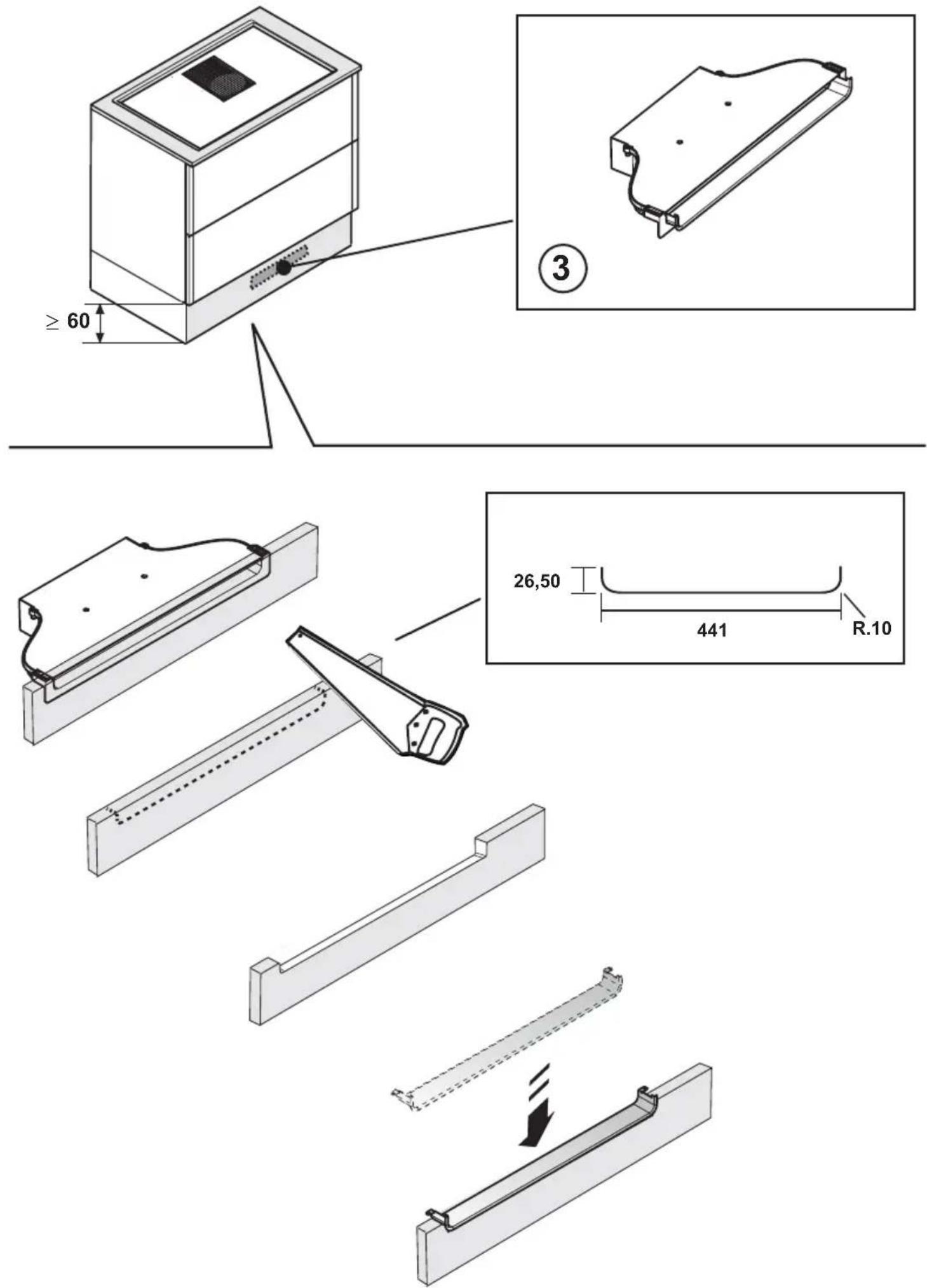
- to optimise the filter installation, it is advisable to cut a slot in the plinth to insert a grille (available on the market)
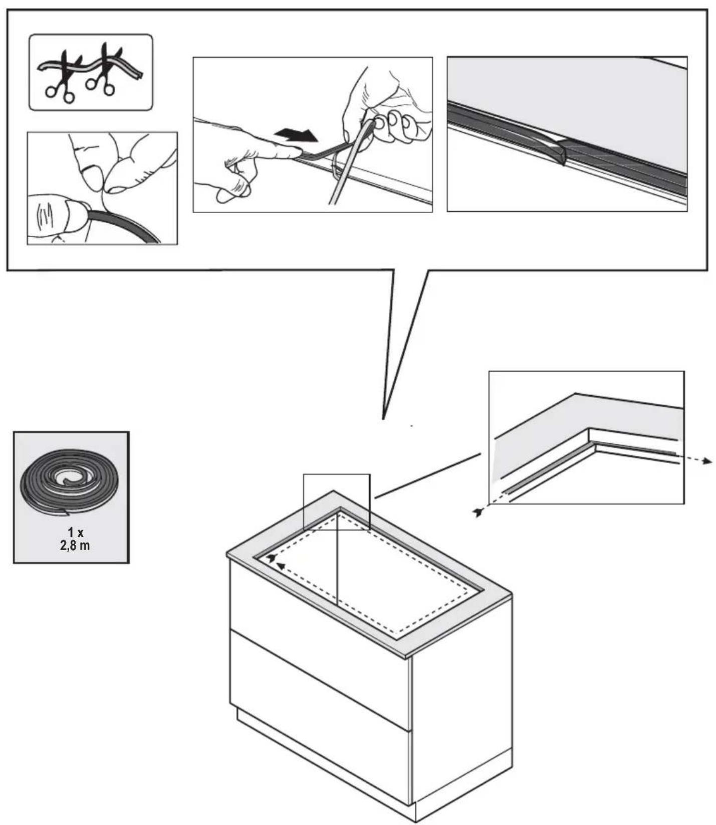
IMPORTANT: use a single component adhesive sealant (S), resistant against high temperatures up to 250°; prior to installation, the surfaces that need to be glued must be carefully cleaned, removing all substances that may compromise adhesion (e.g. release agents, preservatives, grease, oils, powders, old adhesive residue, etc.); the sealant must be evenly distributed along the entire perimeter of the frame; after gluing, leave to dry for approximately 24 hours.
Fig. 1b
CAUTION! Failure to install screws and fasteners in accordance with these instructions may result in electrical hazards.
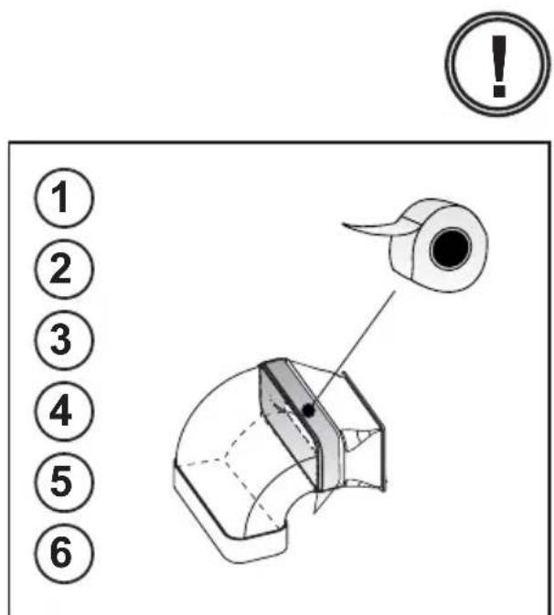
Note: to ensure the correct installation of the product, it is recommended to tape the pipes using an adhesive with the following characteristics:
- soft elastic PVC film, with an acrylic-based adhesive
- which complies with DIN EN 60454 regulations
- flame retardant
- excellent resistance against wear
- resistant against temperature fluctuations
- can be used in low temperatures
4. Operation
Control panel
Note: To select the commands, simply touch (press) the symbols representing them
Keys / Display
- ON/OFF of the hob/extractor
- Cooking zone selection
Cooking zone display
- Increase/Decrease of Power Level and Extraction Power Display of Power Level and Extraction Power
- Activation "STAND_ALONE" timer Display: "STAND_ALONE" Timer / Cooking Zones Timer
- Increase/Decrease time Timer "STAND_ALONE" timer / Cooking Zones Timer
- Activation of Cooking Zones Timer Indicator of Cooking Zones Timer active
-
Automatic Heat Up Activation
-
Temperature Manager activation (Warming Function)
- Pause
- Key Lock
- Indicator Extractor active Activation Filter Saturation Indicator
- Extractor Selection/Activation Extractor Display
Display saturation carbon/ceramic Filter - Grease filter
- Reset Filter Saturation
- Activation of extractor automatic function
USING THE HOB
Before you begin, it is important to know:
All functions of this cooktop are designed to comply with the most stringent safety regulations.
For this reason:
- Some functions will not be activated, or will be automatically deactivated, in the absence of pots on the burners or when they are poorly positioned.
- In other cases the activated functions will be automatically deactivated after a few seconds, if the specific function requires a further setting that has not been selected (e.g.:
"Turn the cooktop on" without "Selecting the cooking zone" and the "Operating temperature", or the "Lock Function" or the "Timer" function).

Caution! In the case (for example) of prolonged use,
the cooking zone may not immediately shut down because it is in the cooling phase; the “H” symbol will appear on the cooking zone display, to indicate the execution of this phase.
Wait for the display to turn off before approaching the cooking zone.
Cooking zone display
The following is shown on the cooking zone displays:
| Cooking zone on | [SWKS] |
| Power Level | [SWWAL] |
| Residual Heat Indicator | [SWWS] |
| Pot Detector |  |
| Temperature Manager Function active |  |
| Lock function active |  |
| Pause function | [SWSN] |
| Automatic Heat UP function | [SWSN] |
Hob characteristics
Safe Activation
The product is activated only in the presence of pots on the cooking zone: the heating process does not start or is interrupted if there are no pots, or if these are removed.
Pot Detector
The product automatically detects the presence of pots on the cooking zones.
Safety Shut Down
For safety reasons, each cooking zone has a maximum operating time, which depends on the maximum power level set.
■ Residual Heat Indicator
When one or more cooking zones shut down, the presence of residual heat is indicated by a visual signal on the corresponding zone display, by way of the “H” symbol.
Operation
Note: Before activating any functions, the desired zone must be activated
Switch-on
Press (touch) briefly ON/OFF (1) hob/extractor: the symbol

lights up;
continuing to press, all the available functions will become visible for a few moments, e, after which only the main ones will remain active; the others can be used, and will be activated, subsequently, during use of the device.
IMPORTANT:
all the available functions will be illuminated with light intensity, which will become more intense only when they are activated.
Press

again to turn off
Note: This function has priority over the others.
- Selecting the cooking zones
Press (touch) briefly the Selection/Display (2) area corresponding to the desired cooking area.
Power Level
The hob features 9 power levels
Touch and slide your fingers along the Selection bar (3): to the right to increase the level of power; to the left to decrease the level of power.
The power level set will be displayed in the
Selection/Display area (2)
Power Booster
The product features a supplementary power level (after level 5), which remains active for 5 minutes, after which the temperature returns to the previously set value.
Touch and slide with your fingers along the Selection bar (3) (above the level 5) and activate the Power Booster
The Power Booster level is indicated in the Selection / Display area (2) with the symbol" P"
Note: the front cooking zones do not have a timed booster; to deactivate the Power Booster, in these areas, touch and slide with the fingers along the Selection bar (3) to decrease the power level.
Key Lock
The Key Lock allows cooktop settings to be blocked, thus preventing accidental tampering, leaving set functions active.
Activation:
- press

(10)
Repeat the operation to deactivate.
Note: if any other function is pressed during the active Key
Lock, the symbol ☐, will flash to indicate that the function is in use and must be deactivated if necessary in order to use the hob.
Automatic Heat UP
The Automatic Heat UP function allows the set power to be reached more quickly; with this function it is possible to cook food faster without the risk of burning it, insofar as the temperature does not exceed the set level. This function is available for power levels 1-8.
Activation:
• from the cooking zone on press (7)
- a flashing "R" is shown in the Display (2) which alternates with the power set in the cooking zone
Increasing the power level of the cooking zone: the Automatic Heat Up function remains active, with the new temperature setting; Decreasing the power level of the cooking zone: the Automatic Heat function is deactivated.
Note: by selecting another cooking zone at the same time,
the symbol (7) will return to being illuminated with a slight intensity light, and it will be possible to proceed, also for this area, to activation of the function; the function remains active in the area where it has already been set, as indicated in the Display (2)
■ Temperature Manager (Warming Function)
Temperature Manager is a control function that allows the maintaining of heat at a constant temperature, at an optimised power level; ideal to keep ready-cooked foods warm. The Temperature Manager function is activated the first time the
key is pressed
The symbol appears in the display (2) of the zone that is working in the Temperature Manager
Note: by selecting another cooking zone at the same time, the symbol (8) will return to being illuminated with a slight intensity light, and it will be possible to proceed, also for this area, to activation of the function; the function remains active in the area where it has already been set, as indicated in the Display (2)
- Press (8) again to deactivate and switch off, until bringing of the level shown in the Display (2) to "☐".
Note: if there are several zones working in the Temperature Manager (Warming Function), first select the desired zone using the Selection zone (2); the function can also be deactivated via the Selection Bar (3), bringing the Power Level to "☐".
Pause
The Pause function allows active functions on the cooktop to be suspended, bringing the cooking power to zero.
Activation:
- press " ||"(9)
- a flashing " ||" is shown in the displays (2)
To deactivate the function:
- press ||(9) the Selection Bar (3) lights up
- press/slide on the Selection Bar (3) to deactivate the function
Note: deactivation restores the conditions of the hob before the pause; the hob continues to work with the same settings previously set.
Note: if after 10 minutes the Pause Function is not deactivated, the hob switches off automatically.
Note: the Pause Function does not affect the extraction.
"STAND ALONE" Timer
The Timer function is a countdown independent of the cooking zones (and the extraction zone).
The timer is activated by pressing the Zone/Display (4)
Use the symbols - + (5) to set the duration of the Timer, which is displayed in the Zone/Display (4)
Note: wait 10 seconds without pressing any other command, so that the countdown starts.
The format of the Timer is 0.00
-0. for the times : which can be set from 0 to 9
- 0G for the minutes : which can be set from 0 to 59
In the Zone/Display (4) the remaining time will be displayed; at the end of the countdown, an acoustic signal will sound
Note: in the display of the countdown, for a time less than 10 minutes, the following format is evident
-
- minutes
- 00 seconds
with fixed light point
To switch off the Timer:
- select Zone/Display (4)
- set the duration of the Timer to 000, via (5) +
Cooking Zones Timer
The Cooking Timer Zone function is a countdown that can be set, also at the same time, on each cooking zone At the end of the period set, the cooking zones switch off automatically and the user is notified with a dedicated acoustic signal.
Activation of the cooking zone timer function
- Touch (press) the Selection/Display area (2) (power level 10)
- Press (6) relating to the cooking zone
Use the symbols - + (5) to set the duration of the Timer, which is displayed in the Zone/Display (4)
during setting the symbol Ⓤ (6) is flashing
Note: wait 10 seconds without pressing any other command, so that the Cooking Zone Timer will start.
Note: by pressing and holding cooking zone timer is reset
(6), the
If desired, repeat the operation for several cooking zones.
Note: each cooking zone can have a different Timer set; in the display (4) he countdown of the cooking zone selected at that moment will appear; if no zone is selected, pressing the Display (4) will display the "STAND-ALONE" Timer countdown.
The countdown mode is the same as the "STAND-ALONE" timer one (see previous paragraph "STAND ALONE" Timer)
When the timer has finished the countdown, an acoustic signal sounds and the cooking zone switches off.
To switch off the Timer:
- select the cooking zone (2)
- set the duration of the Timer to COO, using (5) +
Power Limitation
The Power Limitation function allows setting of the operation of the product, limiting its maximum absorption.
Note: the setting must take place with the hob off, without pressing the ON/OFF (1) key, when the hob is connected to the mains, or when the electric mains are reconnected within the following 2 minutes.
To set the Power Limitation:
- press (A)
(which will be flashing, only for the first 2 minutes after powering of the product)
- continuing to hold down (A) press, one at a time, all the areas of Selection/Display (2) of the cooking zones, anti-clockwise starting from the front right zone (FR)
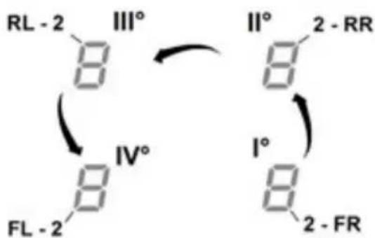
chemical
Chemical reaction diagram showing transformation of compounds RL-2, III°, IV°, and II° with labeled positions and rotation directions- each press will be accompanied by a short audible signal
- once all the Displays (2) have been pressed, it will be possible to release the key (A)
at this point:
- the Display (2) of the left rear zone (RL) will show in alternate sequence the symbols "C" and "0", indicating that it is possible to perform the setting:
select the Display (2-RL)
then scroll on the Selection bar (3), until the symbols "C" and "8", appear
the Display (2-FL) will show the current setting**
$$ 0 = 7. 4 \mathrm{KW} $$
$$ 1 = 4. 5 \mathrm{KW} $$
$$ 2 = 3. 1 \mathrm{KW} $$
** by default the setting is 7.4 KW
To change the Power Limitation setting
- press the Display (2) of the left front area (FL)
- then scroll on the Selection bar (3), to select the new setting
- to save the choice made, press the ON/OFF key (1), for 2 seconds; a prolonged audible signal will be emitted to confirm the successful setting
USING THE EXTRACTOR FAN
Switch-on
Press (touch) briefly ON/OFF (1) hob/extractor: the symbol
lights up;
continuing to press, all the available functions will become visible for a few moments, e, after which only the main ones will remain active; the others can be used, and will be activated, subsequently, during use of the device.
IMPORTANT:
all the available functions will be illuminated with light intensity, which will become more intense only when they are activated.
Press ⏻ again to turn off
Note: This function has priority over the others.
Starting the extractor:
Touch (press) the Selection zone (12) to activate the extractor
Extraction speed (power):
The extractor is equipped with 3 levels of extraction speed (power)
Touch and slide your fingers along the Selection bar (3): to the right to increase the level of power; to the left to decrease the level of power.
The power level set will be displayed in the Selection/Display area (12)
Power Booster
The product has 2 additional power levels (above level 3)
• Power Booster 1 : timed for 15 min.
• Power Booster 2 : timed for 5 min.
after which the power returns to the previously set level.
Touch and slide with the fingers along the Selection bar (12) (over level 3) and activate the Power Booster 1 The Power Booster level 1 is indicated in the Selection / Display area (12) with the number "4" flashing
Touch and slide with the fingers along the Selection bar (12) (over level 3) and activate the Power Booster 2 The Power Booster level 2 is indicated in the Selection / Display area (12) with the symbol" flashing
■ Automatic operation
The hood will turn on at the most suitable speed, adapting the extraction capacity to the maximum cooking level used in the cooking zone.
When the cooking zones are switched off, the hood adapts its extraction speed, decreasing it gradually, to eliminate residual vapours and odours.
To activate this function:
Press (A) _(14)
Repeat the operation to deactivate.
Note: if during automatic operation are selected from the Selection bar (3) the speeds from 1 to 3, the automatic operation is interrupted;
if, instead, the Power Boosters are selected, automatic operation will resume at the end of the timing, while in the
meantime the symbol “(A)” remains flashing.
Filter saturation indicator
The hood indicates when filter maintenance is needed:
Carbon/ceramic odour filters
"FILTER"(13) comes on
Grease filter
"FILTER"(13) flashes
Note: this function is disabled by default (see how to enable it in the paragraph "Activation filter saturation indicator")
- Reset filter saturation
After performing maintenance on the filters (greases and/or carbon/ceramic), press and hold "FILTER" (13);
“FILTER”(13) turns off, restarting the indicator count.
■ Activation filter saturation indicator
This indicator is normally deactivated.
To activate it, proceed as follows:
- turn on the extractor hob via ⏻;
- with the extraction motor and cooking zones off, press the
- long press "HOOD" (11) until the letters "F" - "G" appear alternately flashing in the Display (12)
Selection zone (12)
F = carbon/ceramic odour filters
G
=
grease filter
Carbon/ceramic odour filters
- press on the Display (12) when the letter "F" appears
- press " FILTER" (13) - flashing light
- long press “HOOD” (11) again to confirm the activation of the carbon/ceramic odour filter indicator
Grease filter
- press on the Display (12) when the letter "G" appears
- press " FILTER" (13) - fixed light
- long press “HOOD” (11) again to confirm activation of the grease filter indicator
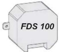
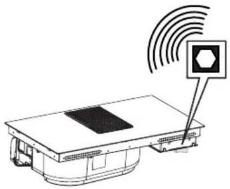
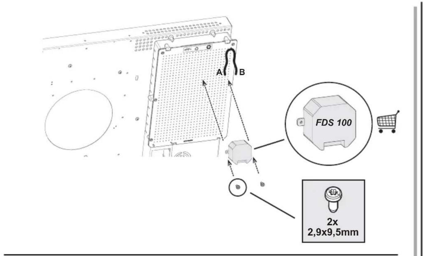
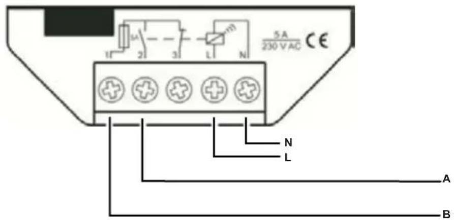
The suction surface is designed to be used in combination with a Window sensor KIT (not provided by the manufacturer)
When installing the Windows sensor KIT (only in the case of use of the surface in SUCTION mode), the suction will stop operating every time when the KIT which with the surface is equipped detects that the window is closed in the room where it is installed.
It is recommended the purchase of the FDS KIT - 100
Elektrotechnik Schabus, available at authorised Elektrotechnik Schabus centres or directly on the Internet site
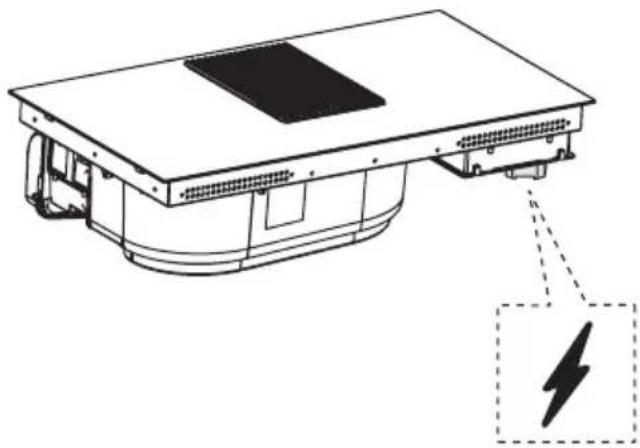
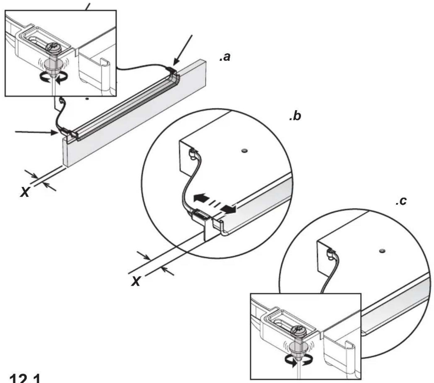
- The electrical connection of the suction surface KIT must be carried out by qualified and specialised technical personnel.
- The manufacturer of the suction surface declines all responsibility for any inconvenience, damage or fire caused by defects and/or problems of malfunctioning and/or incorrect installation of the KIT.
4.1 Power tables
| Power level | Cooking type | Use of level(display combines the experience and cooking habits) | |
| Max power | Boost | Heat | Ideal to quickly increase the temperature of the food up quickly fast boiling in the case of water or quickly heat cooking liquids |
| 8-9 Fry - boil | Ideal for browning, starting to cook, frying frozen products, boiling rapidly | ||
| High power | |||
| 7-8 Brown | - fry - boil - grill | Ideal for frying, keeping the boil, cooking and grilling (for short times, 5-10 minutes) | |
| 6-7 Brown | - cook - stew - fry - grill | Ideal for frying, maintaining a simmer, cooking and grilling (for average times, 10-20 minutes), preheating accessories | |
| Medium power | |||
| 4-5 Cook | - stew - fry - grill | Ideal for stewing, maintaining a light boil, cooking (for longer times). Stir pasta | |
| 3-4 Cook | - simmer - thicken - stir | Ideal for slow cooking (rice, sauces, roasts, fish) in the presence of liquid (e.g. water, wine, broth, milk), stirring pasta | |
| 2-3 Cook | - simmer - thicken - stir | Ideal for slow cooking (volume less than one litre: rice, sauces, roasts, fish) in the presence of liquid (e.g. water, wine, broth, milk) | |
| Low power | |||
| 1-2 Melt | - thaw - keep warm - stir | Ideal for softening butter, gently melting chocolate, thawing small products | |
| 1 Melt | - thaw - keep warm - stir | Ideal for keeping small portions of freshly cooked food warm or keeping the temperature of serving dishes and stirring risotto | |
| OFF | Zero power | Support surface | Hob in stand-by or off (possible presence of residual heat from the end of cooking, signalled by H-L-O) |
4.2 Cooking tables
| Category of foods | Dishes or type of cooking | Power level and cooking pattern | |||
| First stage Powers Second stage Powers | |||||
| Pasta, rice | Fresh pasta Heating water Booster-9 | Cooking pasta and maintaining the boil | 7-8 | ||
| Fresh pasta Heating water Booster-9 | Cooking pasta and maintaining the boil | 7-8 | |||
| Boiled rice Heating water Booster-9 | Cooking pasta and maintaining the boil | 5-6 | |||
| Risotto Frying and roasting 7-8 | Cooking 4-5 | ||||
| Vegetables, legumes | Boiled | Heating | water | Booster-9 | |
| Fried | Heating | oil | 9 | Fry | |
| Sauté | Heating accessory | 7-8 | Cooking | 6-7 | |
| Stewed | Heating accessory | 7-8 | Cooking | 3-4 | |
| Fried | Heating accessory | 7-8 | Browning fried | 7-8 | |
| Meats | Roast | Meat browning with oil (if with butter, power 6) | 7-8 | Cooking | 3-4 |
| Grilled | Pre-heating pan | 7-8 | Grilling on both sides | 7-8 | |
| Browning | Browning with oil (if with butter, power 6) | 7-8 | Cooking | 4-5 | |
| Stew | Browning with oil (if with butter, power 6) | 7-8 | Cooking | 3-4 | |
| Fish | Grilled | Pre-heating pan | 7-8 | Cooking | 7-8 |
| Stew | Browning with oil (if with butter, power 6) | 7-8 | Cooking | 3-4 | |
| Fried | Heating oil or fat | 8-9 | Frying | 7-8 | |
| Eggs | Omelettes | Heating pan with butter or fat | 6 | Cooking | 6-7 |
| Omelettes | Heating pan with butter or fat | 6 | Cooking | 5-6 | |
| Soft boiled/boiled | Heating water Booster-9 | Cooking 5-6 | |||
| Pancakes | Heating pan with butter | 6 | Cooking | 6-7 | |
| Sauces | Tomato | Browning with oil (if with butter, power 6) | 6-7 | Cooking | 3-4 |
| Meat sauce | Browning with oil (if with butter, power 6) | 6-7 | Cooking | 3-4 | |
| Béchamel | Preparing the base (melt butter and flour) | 5-6 | Bring to simmering point | 3-4 | |
| Desserts, creams | Custard | Boil the milk | 4-5 | Keep simmering | 4-5 |
| Puddings | Boil the milk | 4-5 | Keep simmering | 2-3 | |
| Rice pudding | Heat the milk | 5-6 | Keep simmering | 2-3 | |
Boilir ing
5. Maintenance
Hob maintenance
Caution! Before any cleaning or maintenance, make sure the cooking zones are switched off and the heat indicator has turned off.
5.1 Cleaning
The hob must be cleaned after each use.
Important:
Do not use abrasive sponges, scouring pads. Their use, over time, may ruin the glass.
Do not use chemical irritants, such as oven sprays or stain removers.
After each use, leave the hob to cool and clean it to remove deposits and stains caused by food residue.
Sugar or food with a high sugar content damages the hob and must be immediately removed.
Salt, sugar and sand may scratch the glass surface.
Use a soft cloth, paper towel or specific products to clean the hob (follow the Manufacturer's instructions).
DO NOT USE STEAM JET CLEANERS!!!
Important:
If liquids accidentally or excessively leak out of the pots, the drain valve located on the lower part of the product can be opened so as to remove any residue and be able to clean in conditions of maximum hygiene.
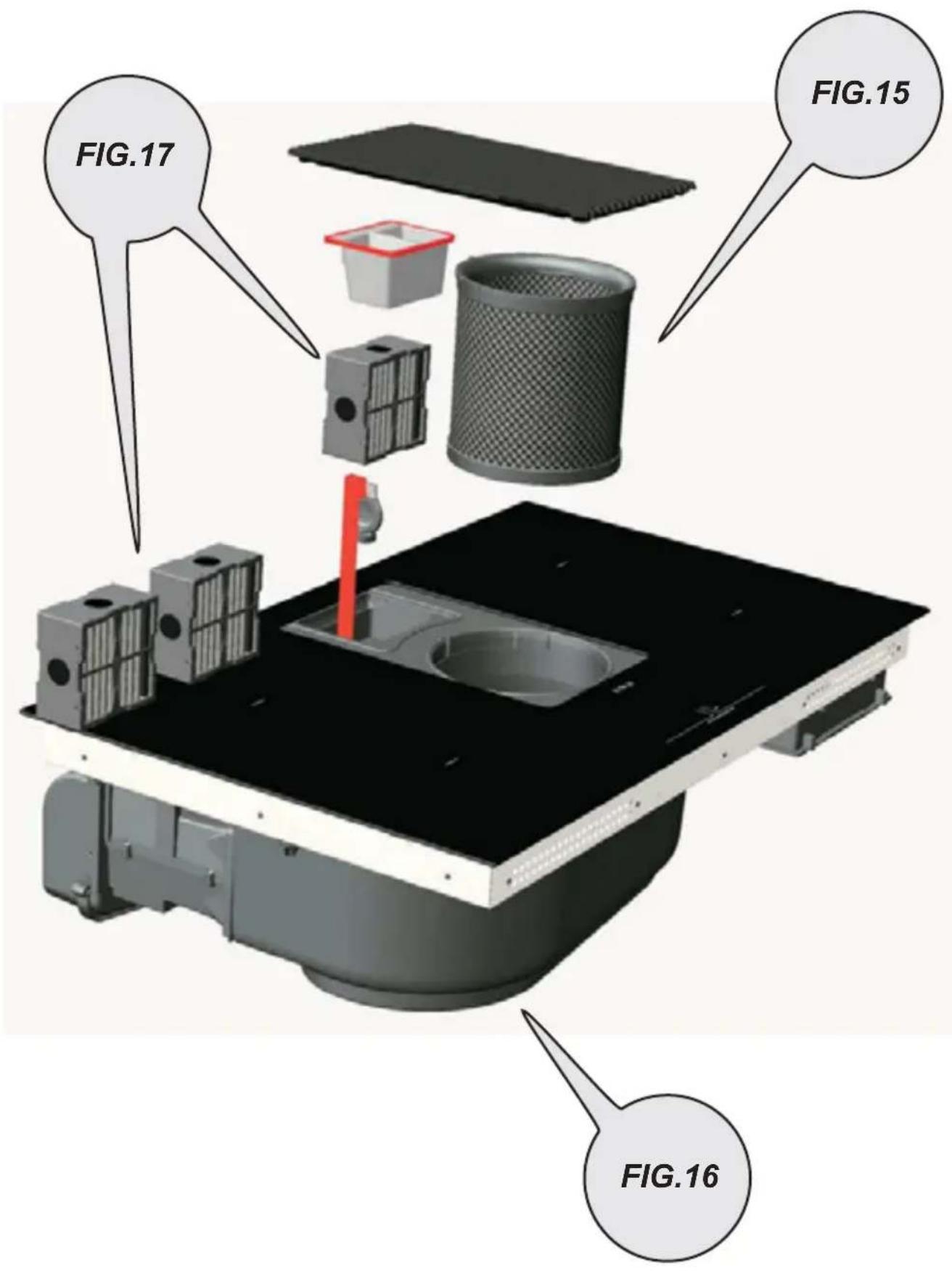
Fig. 16
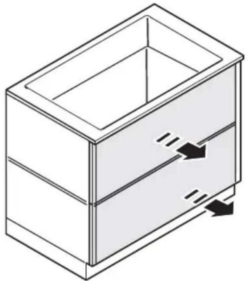
For a more complete and in-depth clean, the lower tray can be completely removed.
Fig. 18a - 18b
Extractor fan maintenance
Cleaning
For cleaning, use ONLY a cloth moistened with neutral liquid detergents. DO NOT USE CLEANING UTENSILS OR TOOLS!
Avoid the use of products containing abrasives.
DO NOT USE ALCOHOL!
Grease filter
Traps grease particles generated by cooking.
Must be cleaned once per month (or when the filter saturation indication system indicates this need), with non-aggressive detergents, either manually or in the dishwasher at a low temperature and in a short cycle.
When cleaned in the dishwasher, the metal grease filter may discolour, but its filtering characteristics remain unchanged.
Fig. 15
Activated carbon filters
(Only for Filtration Version)
Traps unpleasant odours generated by cooking.
The product is equipped with four filter packs that trap odours thanks to the activated carbons. The activated carbons are incorporated into a ceramic structure, making them easily and completely accessible by impurities, thus creating a large absorption surface. Saturation of the activated charcoal ceramic filters occurs after a more or less prolonged use, depending on the type of kitchen and the cleaning frequency of the grease filter. These odour filters cannot be regenerated and must be replaced when the warning lamp turns on.
Fig. 17 - 17a - 17b - 17c
5.2 Troubleshooting
| ERROR CODE DESCRIPTION POSSIBLE CAUSES ERROR REMOVAL | |||
| E2 | The command zone switches off due to an excessively high temperature | The temperature inside the electronic parts is too high | Wait for the hob to cool before reusing it |
| E3 | Container unsuitable | Loss of magnetic properties | Remove the pot |
| E5 | Communication problems between the user interface and induction module | Electricity is not reaching the module; The power cable is incorrectly connected or faulty | Disconnect the hob from the electrical network and check the connection |
| For all other error signals ( E ... U ... C ... ) | Call customer service and report the error code | ||
5.3 Customer service
Before contacting Customer Service
-
Check that you cannot solve the problem yourself based on the points described in "Troubleshooting".
-
Switch the device off and on again to see if the problem resolves itself.
If the fault persists after the above checks, contact the nearest Customer Service.
Residual Heat Indicator
■ Temperature Manager (Warming Function)
chemical
Chemical reaction diagram showing transformation of compounds RL-2, III°, IV°, and II° with labeled positions and directional arrows$$ 0 = 7, 4 \mathrm{KW} $$
$$ 1 = 4, 5 \mathrm{KW} $$
$$ 2 = 3, 1 \mathrm{KW} $$
chemical
Chemical reaction diagram showing transformation of compounds RL-2, III°, IV°, and II° with labeled positions and rotation directions$$ 0 = 7, 4 \mathrm{KW} $$
$$ 1 = 4, 5 \mathrm{KW} $$
$$ 2 = 3, 1 \mathrm{KW} $$
5.3 Service assistance
chemical
Chemical reaction diagram showing transformation of compounds RL-2, III°, IV°, and II° to flucturated products with labeled positions 2-RR, 2-FR, 2-FR, I°, I°$$ 0 = 7, 4 \mathrm{KW} $$
$$ 1 = 4, 5 \mathrm{KW} $$
$$ 2 = 3, 1 \mathrm{KW} $$
chemical
Chemical reaction diagram showing transformation of compounds III° and IV° into II° and I° with labeled positions and rotation directions$$ 0 = 7, 4 \mathrm{KW} $$
$$ 1 = 4, 5 \mathrm{KW} $$
$$ 2 = 3, 1 \mathrm{KW} $$
chemical
Chemical reaction diagram showing transformation of compounds RL-2, III°, IV°, and II° with labeled positions and directional arrows$$ 0 = 7, 4 \mathrm{KW} $$
$$ 1 = 4, 5 \mathrm{KW} $$
$$ 2 = 3, 1 \mathrm{KW} $$
Activering indicator Verzadiging Filters
- selecteer Zone/Display (4)
chemical
Chemical reaction diagram showing transformation of compounds RL-2, III°, IV°, and II° to flucturated products with labeled positions I°, II°, 2-RR, 2-FR$$ 0 = 7, 4 \mathrm{KW} $$
$$ 1 = 4, 5 \mathrm{KW} $$
$$ 2 = 3, 1 \mathrm{KW} $$
text_image
10 9 8 7 5 3 O I I I I I I I I I I I P 6 11 6 HOOO 2 8-12 8 FILTER-13 -6 1 ON/OFF (A)-14 8 2 ? 8 2chemical
Chemical reaction diagram showing transformation of compounds RL-2, III°, IV°, and II° with labeled positions and directional arrows$$ 0 = 7, 4 \mathrm{KW} $$
$$ 1 = 4, 5 \mathrm{KW} $$
$$ 2 = 3, 1 \mathrm{KW} $$
$$ 0 = 7, 4 \mathrm{KW} $$
$$ 1 = 4, 5 \mathrm{KW} $$
$$ 2 = 3, 1 \mathrm{KW} $$
chemical
Chemical reaction diagram showing transformation of compounds RL-2, III°, IV°, and II° to flucturated products with labeled positions I° and 2-FR$$ 0 = 7, 4 \mathrm{KW} $$
$$ 1 = 4, 5 \mathrm{KW} $$
$$ 2 = 3, 1 \mathrm{KW} $$
text_image
10 9 8 7 5 3 O I I I I I I I I I I I P 6 2 8 4 6- 11 HOOD 6 2 8-12 FILTER-13 6- ON/OFF (A)-14 2 ? 8 2Кнопки / дисплей
chemical
Chemical reaction diagram showing transformation of compounds RL-2, III°, IV°, and II° with labeled positions and directional arrowschemical
Chemical reaction diagram showing transformation of compounds RL-2, III°, IV°, and II° with labeled positions and rotation directionschemical
Chemical reaction diagram showing transformation of compounds RL-2, III°, IV°, and II° to flucturated products with labeled positions I° and 2-FRchemical
Chemical reaction diagram showing transformation of compounds RL-2 and FL-2 into II°, III°, IV°, and I° with labeled positions and rotation directions(6) Comcastي (6) Comcastي