ENF430BL - Cooker ELICA - Free user manual and instructions
Find the device manual for free ENF430BL ELICA in PDF.

User questions about ENF430BL ELICA
0 question about this device. Answer the ones you know or ask your own.
Ask a new question about this device
Download the instructions for your Cooker in PDF format for free! Find your manual ENF430BL - ELICA and take your electronic device back in hand. On this page are published all the documents necessary for the use of your device. ENF430BL by ELICA.
USER MANUAL ENF430BL ELICA
natural_image
Technical line drawing of a mechanical assembly with a flat top and internal components (no text or symbols)Models: ENF430BL ENF436BL
Use, care, and installation guide
READ AND SAVE THESE INSTRUCTIONS
LISEZ CES INSTRUCTIONS ET CONSERVEZ-LES
LEA Y CONSERVE ESTAS INSTRUCCIONES
LIB0190426 Printed in Mexico
ENGLISH
Contents
Important safety notice ....3
Electrical & installation requirements....5
List of materials 6
Cutout 6
Product dimensions 7
Installation 8
Description of the hood & controls....10
Use 11
Use of the extractor fan ....14
Power tables 15
Cooking tables 16
User servicing & maintenance intructions ....17
Troubleshooting....18
Electrical diagram 19
Warranty 20
READ AND SAVE THESE INSTRUCTIONS
We have provided many important safety messages in this manual and on your appliance. Always read and obey all safety messages.

This is the safety alert symbol.
This symbol alerts you to potential hazards that can kill or hurt you and others.
All safety messages will follow the safety alert symbol and either the word "DANGER" or "WARNING."
These words mean:
DANGER
You can be killed or seriously injured if you don't immediately follow instructions.
WARNING
You can be killed or seriously injured if you don't follow instructions.
All safety messages will tell you what the potential hazard is, tell you how to reduce the chance of injury, and tell you what can happen if the instructions are not followed.
⚠️ Important Safety Notice
⚠ WARNING
To reduce the risk of fire, electrical shock, injury to persons, or damage when using the cooktop, follow basic precautions, including the following:
CAUTION
Do not store items of interest to children in cabinets above a cooktop – Children climbing on the cooktop could be seriously injured.
- Proper Installation – Be sure your cooktop is properly installed and grounded by a qualified technician.
- Never use your cooktop for warming or heating the room.
- Do not leave children alone – Children should not be left alone or unattended in area where cooktop is in use. They should never be allowed to sit or stand on any part of the cooktop.
- Wear proper apparel – Loose-fitting or hanging garments should never be worn while using the cooktop.
- User servicing – Do not repair or replace any part of the cooktop unless specifically recommended in the manual. All other servicing should be referred to a qualified technician.
- Storage on cooktop – Flammable materials should not be stored near surface units.
- Do not use water on grease fires – Smother fire or flame or use dry chemical or foam-type extinguisher.
- Use only dry potholders - Moist or damp potholders on hot surfaces may result in burns from steam. Do not let potholder touch hot heating elements. Do not use a towel or other bulky cloth.
- DO NOT TOUCH SURFACE UNITS OR AREAS NEAR UNITS – Surface units may be hot even though they are dark in color. Areas near surface units may become hot enough to cause burns.
- During and after use, do not touch, or let clothing or other flammable materials contact surface units or areas near units until they have had sufficient time to cool. Among those areas are the cooktop and surfaces facing the cooktop.
- Use proper pan size – This cooktop is equipped with one or more surface units of different size. Select utensils having flat bottoms large enough to cover the surface unit heating element. Proper relationship of utensil to burner will also improve efficiency.
- Never leave surface units unattended at high heat settings - Boilover causes smoking and greasy spillovers that may ignite.
- Glazed cooking utensils - Only certain types of glass, glass/ceramic, ceramic, earthenware, or other glazed utensils are suitable for cooktop service without breaking due to the sudden change in temperature.
- Utensil handles should be turned inward and not extend over adjacent surface units – To reduce the risk of burns, ignition of flammable materials, and spillage due to unintentional contact with the utensil, the handle of a utensil should be positioned so that it is turned inward, and does not extend over adjacent surface units.
- Do not cook on broken cooktop – If cooktop should break, cleaning solutions and spillovers may penetrate the broken cooktop and create a risk of electric shock. Contact a qualified technician immediately.
- Clean cooktop with caution – If a wet sponge or cloth is used to wipe spills on a hot cooking area, be careful to avoid steam burn. Some cleaners can produce noxious fumes if applied to a hot surface.
- Do not place metal objects such as knives, forks, spoons and lids on the hob surface as they may overheat.
FOR UNITS WITH VENTILATING
- Clean frequently – Grease should not be allowed to accumulate on cooktop or filter.
FOR UNITS WITH COIL ELEMENTS
- Make sure reflector pans or drip bowls are in place - Absence of these pans or bowls during cooking may subject wiring or components underneath to damage.
- Protective liners – Do not use aluminum foil to line surface unit drip bowls, except as suggested in the manual. Improper installation of these liners may result in a risk of electric shock, or fire.
- Do not soak removable heating elements - Heating elements should never be immersed in water.
This induction cooktop generates and uses ISM frequency energy that heats cookware by using an electromagnetic field. It has been tested and complies with Part 18 of the FCC Rules for ISM equipment. This induction cooktop meets the FCC requirements to minimize interference with other devices in residential installation.
This induction cooktop may cause interference with television or radio reception. If interference occurs, the user should try to correct the interference by:
- Relocating the receiving antenna of the radio or television.
- Increasing the distance between the cooktop and the receiver.
- Connecting the receiver into a different outlet.
It is the user's responsibility to correct any interference.
NOTE: People with a pacemaker or similar medical device should use care when standing near this induction cook-top while it is on. The electromagnetic field may affect the pacemaker or similar device. Consult your doctor or the manufacturer of the pacemaker or similar medical device for additional information about its effects with electromagnetic fields of the induction cooktop.
CAUTION
Strictly observe the following instructions:
- The device must be disconnected from the electrical network before performing any installation work.
- Installation or maintenance must be performed by a qualified technician, in compliance with the manufacturer's instructions and with local safety regulations. Do not repair or replace any part of the device unless specifically stated in the operating manual.
- Earthing the device is compulsory.
- Do not use multiple sockets or extension cords.
- Once installation is complete, the electrical components must no longer be accessible by the user.
- The device and its accessible parts heat up during use.
- Be careful not to touch the heating elements.
- Ensure that children do not play with the device; keep children away and supervise them, as the accessible parts may become very hot during use.
- For people with pacemakers and active implants it is important to check, prior to using the induction hob, that their pacemaker is compatible with the device.
- During and after use, do not touch the heating elements of the device.
- Avoid contact with cloths or other flammable materials until all the device components have sufficiently cooled.
- Do not place flammable materials on or near the device.
• Overheated fats and oils easily catch fire. Supervise the cooking of foods rich in fat and oil.
- If the surface is cracked, switch off the device to avoid the possibility of an electric shock.
- The device is not intended to be run with an external timer or a separate remote control system.
- Unattended cooking on a hob with oil or fat may be dangerous and may cause a fire.
- The cooking process must be supervised. A short-term cooking process must be constantly monitored.
- NEVER attempt to put fires out using water. Instead, turn off the device and smother the flames, for example with a lid or a fire blanket. Fire hazard: do not rest objects on the cooking surfaces.
- Do not use steam cleaners.
- Before connecting the device to the electrical network: check the data plate (on the bottom of the device) to ensure that the voltage and power correspond to the network values and that the connection socket is suitable. If in doubt, consult a qualified electrician.
△IMPORTANT
- After use, turn off the hob and do not rely on the pan detector.
- Prevent liquids from boiling over, so turn the heat down when boiling or heating liquids.
- Do not leave the heating elements turned on with empty pots and pans or with no pans.
- Switch off the relevant hot plate when you have finished cooking.
- Never use aluminium foil for cooking and never place products packaged in aluminium on the hob. The aluminium would melt and irreparably damage your device.
-
Never heat a tin or can containing foods without opening it first: it might explode.
-
High power levels such as the Booster function should not be used to heat certain liquids, such as oil for frying. Excessive heat may be dangerous. In these cases, we recommend the use of a lower power level.
- Containers must be placed directly on the hob center. Under no circumstances may any other objects be placed between the pan and the hob.
- If the temperature becomes high, the device automatically decreases the power level of the cooking zones.
- Before doing any cleaning or maintenance work, disconnect the device from the mains power supply by removing the plug or turning off the mains switch.
- Wear protective gloves for all installation and maintenance operations.
- The device can be used by children over the age of eight and by people with impaired physical, sensory or mental abilities or lacking in experience or the necessary knowledge provided that they are supervised or after they have received instruction about how to safely use the device and understand the inherent dangers.
- Cleaning and maintenance must never be performed by children unless they are properly supervised. The room must be properly ventilated when the device is used at the same time as other gas-powered devices, or powered by other fuel.
The device must be regularly cleaned both internally and externally (AT LEAST ONCE A MONTH), in strict accordance with the maintenance instructions. Failure to follow the rules for device cleaning and filter replacement and cleaning may result in a fire hazard. Food must never be cooked flambè. Using a naked flame may damage the filters and cause a fire hazard; it must, therefore, be avoided under all circumstances. Extra care must be taken when frying to prevent the oil from overheating and catching fire.
PLEASE NOTE:
- The accessible parts of the device may become hot when cooktop is switched on.
- Do not connect the device to the electric power supply until installation has been fully completed. The regulations laid down by local authorities must be strictly followed with regard to the technical and safety measures to adopt for fume extraction.
•The extracted air must not be conveyed through the same ducts used to extract the fumes generated by gas combustion or other types of combustion devices. Never use the device without the grille properly installed. - When the device is used together with other devices powered with non-electrical energy, the negative pressure of the room must not exceed 4 Pa (4 x 10 • 5 bar). This manual must be stored for future consultation at any time. If sold, transferred or moved, it must remain with the device.
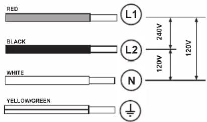
ELECTRICAL REQUIREMENTS
120/240V 3 wire 60Hz
text_image
RED BLACK WHITE YELLOW/GREEN L1 L2 N 240V 120V 120V- Disconnect the device from the electrical network.
- The installation must be performed by professionally qualified personnel familiar with the applicable installation and safety standards.
- The manufacturer declines any liability to people, animals or things in the case of failure to follow the guidelines provided in this chapter.
- Make sure that the voltage on the rating plate on the bottom of the device corresponds to that of the house where it will be installed.
- Do not use extension cords.
- Earthing is required by law
IMPORTANT
Observe all governing codes and ordinances.
It is the customer's responsibility:
• To contact a qualified electrical installer.
- To assure that the electrical installation is adequate and in conformance with:
National Electrical Code, ANSI/NFPA 70 — latest edition*, or CSA Standards C22.1-94, Canadian Electrical Code, Part 1 and C22.2 No.0-M91 - latest edition** and all local codes and ordinances.
- If codes permit and a separate ground wire is used, it is recommended that a qualified electrician determine that the ground path is adequate.
- Do not ground to a gas pipe.
- Check with a qualified electrician if you are not sure cooktop is properly grounded.
- Do not have a fuse in the neutral or ground circuit.
CAUTION
Risk of electric shock, frame grounded to neutral of appliance through a link. Grounding through the neutral conductor is prohibited for new branch-circuit installations (1996 NEC); mobile homes; and recreational vehicles, or in an area where local codes prohibit grounding through the neutral conductor. When installed where it is not permitted to ground through the neutral, the 3-conductor cord or cable assembly must be replaced by a 4-conductor cord or cable assembly. See manufacturer's instructions.
IMPORTANT
USE COPPER OR ALUMINIUM CONDUCTORS.
- Save Installation Instructions for electrical inspector's use.
- The appliance should be connected directly to the fused disconnect (Or circuit breaker) box through metal electrical conduit.
- Wire sizes must conform to the requirements of the National Electrical Code ANSI/NFPA 70 — latest edition*, or CSA Standards C22.1-94, Canadian Electrical Code Part 1 and C22.2 No. O-M91 - latest edition** and all local codes and ordinances.
- A U.L.- or C.S.A.-listed conduit connector must be provided at each end of the power supply conduit (at the appliance and at the junction box).
- Copies of the standards listed may be obtained from:
* National Fire Protection Association Batterymarch Park Quincy, Massachusetts 02269
** CSA International 8501 East Pleasant Valley Road Cleveland, Ohio 44131-5575
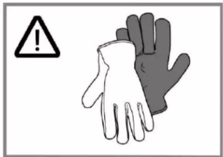
BEFORE INSTALLING
At least two people are necessary for installation. Wear gloves to protect against sharp edges.
text_image
Warning symbol with exclamation mark and two gloves, one open showing hand, one closed showing suitThe exhaust air should not be vented into a wall, a ceiling, or a concealed space of a building.
To eliminate the risk of burns or fire by reaching over heated surface units, cabinet storage space located above the surface units should be avoided.
BOTH ELECTRIC AND MECHANICAL INSTALLATION MUST BE CARRIED OUT BY SPECIALISED PERSONNEL.
The cooktop is designed to be built into a work top with a minimum thickness of 3 cm for both types of installation.
- The minimum distance between the hob and the wall must be at least 5 cm in front, at least 4 cm on the sides and at least 50 cm from overhead wall units.
NB = The recommended distances are given as examples: when planning the spaces, the indications of the kitchen manufacturer must be observed.
LIST OF MATERIALS
Supplied Part Pieces
| Cooktop assembly | 1 |
| Grease filter | 1 |
| Adhesive tape for glass | 30": 1 36": 2 |
| Round transition | 1 |
Supplied Part Pieces
| Spring for installation | 4 | |
| Spacers .5 mm | 8 | |
| Spacers 1 mm | 4 | |
| Spacers 2 mm | 4 | |
| Screws 4.2 x 8 mm | 2 | |
| Torx 20 adapter | 1 | |
| Insulating tape | 1 | |
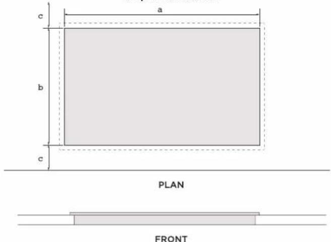
CUTOUT
Top Installation
text_image
a b c PLAN FRONTFlush Installation
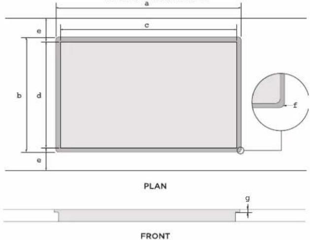
text_image
a c e b d e PLAN g FRONTModel Model
| ENF430BL ENF436BL | ||
| a 28 | 34" (73.03 cm) 34 | 516" (87.79 cm) |
| b 21 | 18" (53.65 cm) | |
| c 1 | ^15/_16" (5 cm) minimum | |
Model Model
| ENF430BL ENF436BL | ||
| a 30 | 716" (77.35 cm) 36 | 18" (91.8 cm) |
| b 22 | 13" (56.76 cm) | |
| c 28 | 34" (73.03 cm) 34 | 916" (87.79 cm) |
| d 21 | 18" (53.65 cm) | |
| e 1 | 1516" (5 cm) minimum | |
| f 4 x ∅ 7 | ||
| g | 14" (0.63 cm) | |
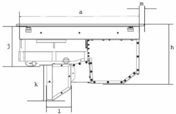
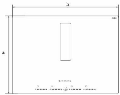
PRODUCT DIMENSIONS
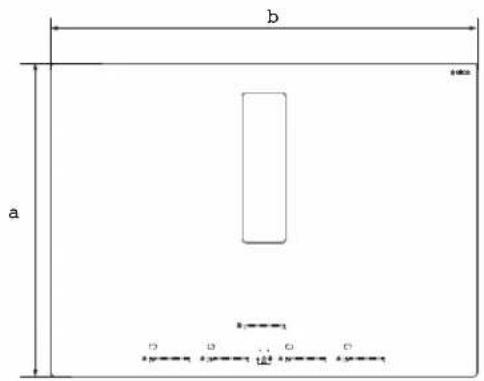
text_image
b a b=1 0.5=0.24 0.5=0.1
text_image
c i d e h g fPLAN FRONT

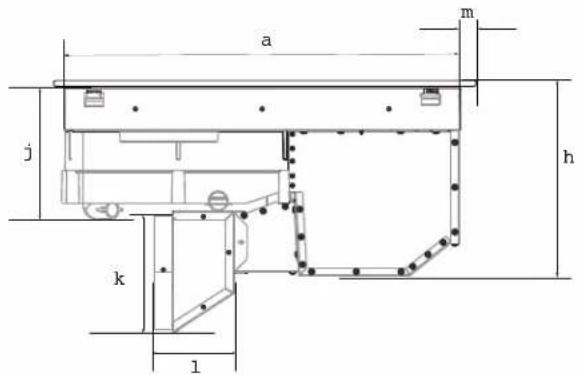
text_image
a m j h k lPROFILE
| Model Model | ||
| ENF430BL ENF436BL | ||
| a 22 | 732" (56.46 cm) | |
| b 30 | 2164" (77.05 cm) 36" | (91.5 cm) |
| c 28 | 1364" (71.64 cm) | 34" (86.39 cm) |
| d 2 | 1732" (6.45 cm) | |
| e 13 | 316" (33.48 cm) | |
| f 16 | 916" (42.1 cm) | |
| g 10 | 58" (27.05 cm) | |
| Model Model | ||
| ENF430BL ENF436BL | ||
| h 10 | 316" (25.9 cm) | |
| i 1" (2.56 cm) | ||
| j 6 | 1316" (17.29 cm) | |
| k 6 | 1332" (16.33 cm) | |
| l 4 | 1584" (10.75 cm) | |
| m | 2132" (1.7 cm) | 58" (1.66 cm) |
ACCESSORIES AND CONSUMABLE PARTS
| KIT | # Part |
| Duct Kit | KIT0192361 |
| Carbon Filters Kit | KIT0192765 |
INSTALLATION
PREPARATION FOR INSTALLATION
Before starting the installation:
- After unpacking the product, check that it has not been damaged during transport and in the event of problem, please contact the reseller or the customer support service before installing it.
- Check that the product is the right size for the installation area.
- Check for accessories (e.g. bags containing screws, warranty certificates, etc.) inside the packaging (placed there for transport reasons). Remove and keep them safe, if present.
- Also check that there is a power socket near the installation area.
PREPARING THE CABINET FOR INSTALLATION:
- The product cannot be installed above cooling appliances, dishwashers, heaters, ovens, washing machines and dryers.
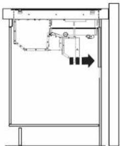
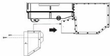
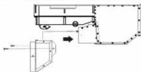
- If your air exhaust is rectangular, throw away the round transition.
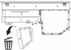
text_image
Diagram showing a trash bin with an arrow indicating direction, likely illustrating a waste sorting or disposal process.IMPORTANT
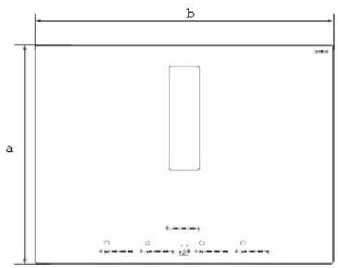
- Create the cut-outs in the cabinet before inserting the hob and carefully remove any shavings or sawdust.
- For the air outlet of the round transition, a 6" cut must be made in the cabinet, considering 12.95 cm from top to the center of the grill outlet.
natural_image
Pure architectural floor plan lines without any text, numbers, or symbols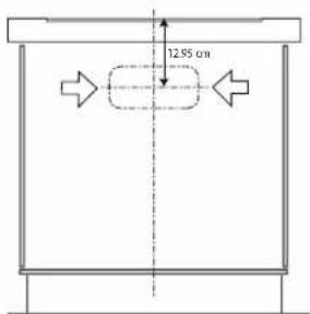
text_image
12.95 cm- A cutout is required to make the connection through the countertop, consider that the cable conduit measurement is 1.5 m (4.9 ft) to reach the connection to your electrical installation.
CAUTION
Failure to install screws and fasteners in accordance with these instructions may result in electrical hazards.
Note: to ensure the correct installation of the product, it is recommended to tape the pipes using an adhesive with the following characteristics:
- soft elastic PVC film, with an acrylic-based adhesive
• compliant with DIN EN 60454 regulations - flame retardant
• excellent resistance to wear
• resistant to temperature fluctuations
• can be used at low temperatures
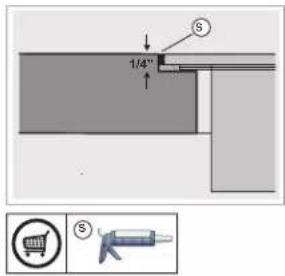
IMPORTANT
Use a single-component adhesive sealant (S), which withstands temperatures up to 250°; before installation, thoroughly clean the surfaces to stick and eliminate any substance that may compromise adhesion, (e.g. release agents, preservatives, oil, dust, traces of old adhesives, etc.); the adhesive should be uniformly spread all around the outside of the frame; after sticking, leave the adhesive to dry for about 24 hours.
text_image
1/4" S S4-WIRE CABLE FROM HOME POWER SUPPLY TO 4-WIRE CABLE FROM COOKTOP
IMPORTANT
Use the 4-wire cable from home power supply in the U.S. where local codes do not allow grounding through homes and campers, new construction, and in Canada.
text_image
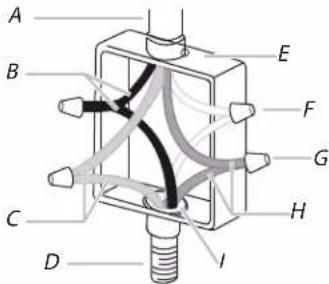
A B C D E F G H IA. Cable from home power supply
B. Black wires (phase)
C. Green or yellow-green ground wires (ground)
D. 4-wire cable from cooktop
E. Junction box.
F. White wires.
G. UL listed wire connector (not supplied)
H. Red wires (Phase).
I. UL listed or CSA approved conduit connector (not supplied).
- Connect the 2 black wires together using the UL listed wire connectors.
- Connect the 2 red wires together using the UL listed wire connectors.
- Connect the 2 white wires together using the UL listed wire connectors.
- Connect the green (or yellow-green) ground from the cooktop cable ti the green (or yellow-green) ground wire (in the junction box) using the UL listed wire connectors.
- Install junction box cover.4-wire cable from home power supply to 4-wire cable from Cooktop - U.S. Only.
TOP INSTALLATION FLUSH INSTALLAT
- Turn the cooktop upside down on a protective cover.
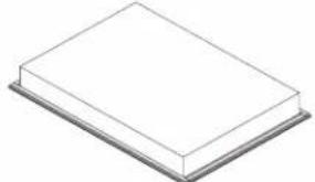
natural_image
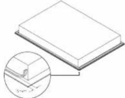
Simple 3D illustration of a rectangular block on a flat base (no text or symbols)- Apply adhesive foam seal around the glass overhang, 5mm from the edge of the glass. Ensure the adhesive side facing is down to form a continuous seal around the cooktop.
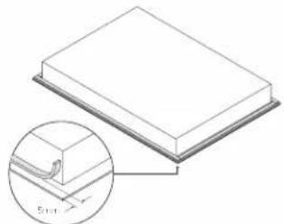
natural_image
Technical illustration of a rectangular block with a magnified inset showing a small curved component (no text or symbols)- Trim the excess sealing material using a sharp cutter or trimmer knife. Take care not to damage the benchtop.

natural_image
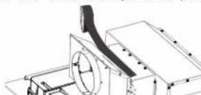
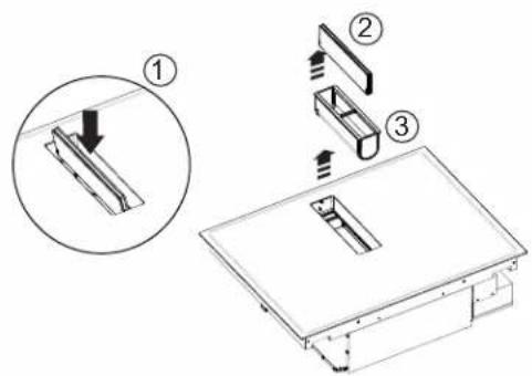
Diagram showing a rectangular block on a flat surface with an inset magnified view of a thin wire or wire joint (no text or symbols)- Install the transition on the bottom of the plate, make sure that the transition flaps are on the outside and push it to the bottom. Secure it with 2 screws (4.2 x 8 mm)
flowchart
graph TD
    A["Component"] --> B{Flow}
    B --> C["Part 1"]
    B --> D["Part 2"]
    style A fill:#f9f,stroke:#333
    style B fill:#ccf,stroke:#333
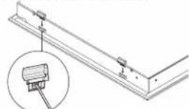
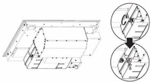
- Attach the four side clips to the cooktop chassis. Make sure the clips are oriented correctly, press the center tab with a flat screwdriver to pass the clip through and secure against the plate..

natural_image
Technical line drawing of a mechanical bracket with mounting holes and a magnified inset showing a mounted component (no text or symbols)-
Lift the cooktop and place it in the center by dropping carefully both sides of the grill at the same time.
-
Clean the cooktop with a cloth.
N
- Prepare the countertop for flush installation. Use a router to cutout the edges of the countertop to specified depth (.63cm). Ensure all bare edges are sealed.
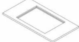
- Turn the cooktop upside down on a protective cover & apply adhesive foam seal around the glass overhang, 5mm from the edge of the glass. Ensure the adhesive side facing is down to form a continuous seal around the cooktop.
natural_image
Illustration of a rectangular block placed on a flat surface with an inset showing a small detail (no text or symbols)- Install the transition on the bottom of the plate, make sure that the transition flaps are on the outside and push it to the bottom. Secure it with 2 screws (4.2 x 8 mm)
text_image
Technical diagram showing a mechanical assembly with labeled components and directional arrow indicating motion or flow.- Place tape over the transition joint to prevent air from escaping.
natural_image
Technical line drawing of a mechanical assembly with no visible text or symbols- Attach the four side clips to the cooktop chassis. Ensure the clips are oriented correctly, press the center flap of the clip to pass through and secure.
natural_image
Technical line drawing of a mechanical bracket assembly with a magnified inset showing a component detail (no text or symbols)-
Lift the cooktop and place it in the center by dropping carefully both sides of the grill at the same time.
-
If necessary, spacers should be installed to adjust the size of the plate to the space.
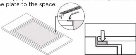
text_image
e plate to the space.- Apply silicone in the gap between countertop and cook-top. Wipe off any excess silicone.
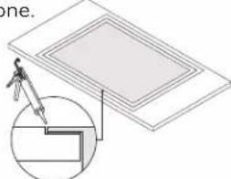
text_image
one.- Clean the cooktop carefully with glass cleaner and a cloth.
DESCRIPTION OF THE HOOD AND CONTROLS
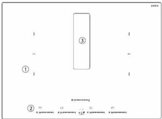
text_image
① ③ ②1-Cookingzones
2 - Control panel
3 - Extractor fan
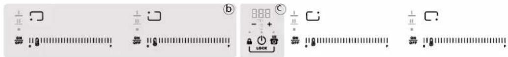
text_image
Digital display control interface showing analog clock, lock, and numeric keypad with labeled buttons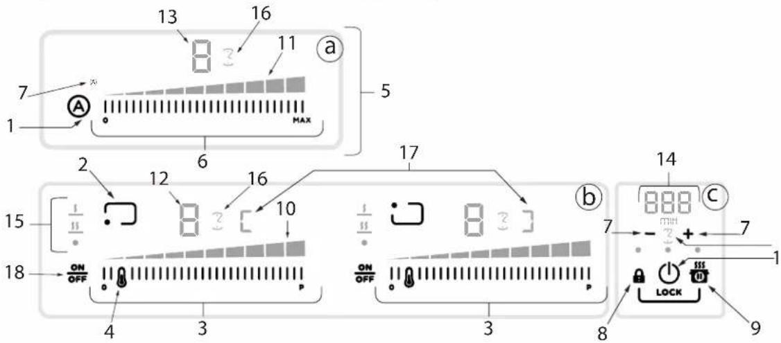
text_image
13 16 11 a 7 1 MAX 5 2 6 17 15 12 16 10 ON OFF 4 3 ON OFF 3 8 14 888 c 7 + 7 1 LOCK 9Keys Display / LED
| 1 ON/OFF of the hob / extractor fan for hob 10 View power level | |||
| 2 Cooking zone position indicator 11 View extraction speed (power) | |||
| 3 | Cooking zone selection Increase/Decrease power level | 12 Cooking zone display | |
| 4 Temperature manager activation 13 Extractor fan display | |||
| 5 | Keys fan | 14 | Timer display |
| 6 | Extractor fan selection Increase/Decrease extraction speed (power) | 15 | Temperature manager display |
| 7 | Activate timer Increase/Decrease timer value | 16 | Timer indicator active |
| 8 | Key lock | 17 | Bridge indicator active |
| 8+9 | Child lock | ||
| 9 | Pause | ||
| 18 | ON/OFF Cooking zone | ||
USE

ON

OFF
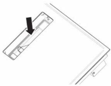
- Turn around the flap by pushing down one side.
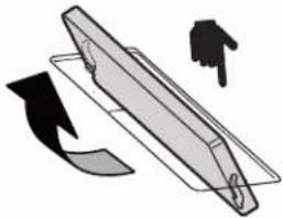
natural_image
Diagram of a mechanical component with arrows indicating motion, no text or symbols present- Turn on the hob touching the power button.

text_image
Diagram showing a mechanical component with a magnified view highlighting a specific feature, including a warning symbol and a hand icon.- Touch the "A" button to turn on the fan.
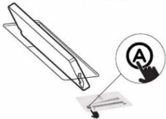
text_image
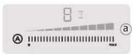
Diagram showing a mechanical component with an annotation pointing to a labeled point 'A' and a cursor icon.- Touch and swipe to the right to increase power.
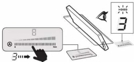
text_image
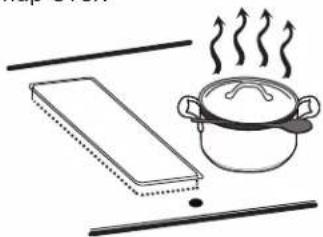
Diagram illustrating smart home control interface with display, navigation, and LCD screen displaying '3' and '8'- The extractor will start working.
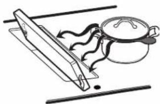
natural_image
Simple line drawing of a cooking pan with a lid and a cooking pot, no text or symbols presentThe extractor will keep off you don't turn around the flap.
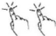
natural_image
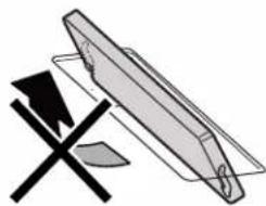
Simple line drawing of a pencil and a cross symbol (no text or labels)It will keep off even if you:
- Touch the "A" button
natural_image
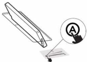
Technical line drawing of a mechanical component with an inset showing a labeled circular icon (no text or symbols present)• Or if you try to increase power
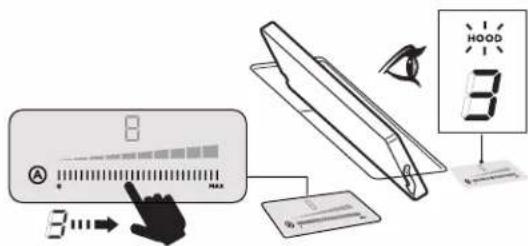
text_image
Diagram illustrating smart home control interface with touchscreen, LCD screen, and 3D display showing 'HOOD 3'The motor will not start and there will be no extraction until you turn the flap over.
natural_image
Simple line drawing of a cooking pan with a pot and steam rising (no text or symbols)The induction cooking system is based on the physical phenomenon of magnetic induction. The main characteristic of this system is the direct transfer of energy from the generator to the pot.
Advantages:
When compared to electric hobs, your induction hob is:
- Safer: lower temperature on the glass surface.
- Faster: shorter food heating times.
- More accurate: the hob immediately reacts to your commands
- More efficient: 90% of the absorbed energy is transformed into heat. Moreover, once the pot is removed from the hob, heat transmission is immediately interrupted, avoiding unnecessary heat losses.
COOKING CONTAINERS

Use only pots bearing the symbol
Important:
To avoid permanent damage to the hob surface,
DO NOT USE:
- containers with less than perfectly flat bottoms.
- metal containers with enamelled bottoms.
- containers with a rough base, to avoid scratching the hob surface.
- never place hot pots and pans on the surface of the hob's control panel
- do not slide pans across the cooking surface.
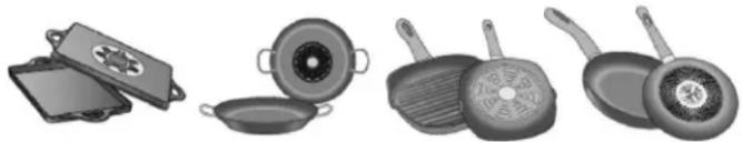
natural_image
Illustration of kitchen utensils including a fire kit, pan, and cooking panes (no text or symbols)PRE-EXISTING CONTAINERS
Induction cooking uses magnetism to generate heat. Containers must therefore contain iron. Check if the pot material is magnetic using a magnet. Pots are not suitable if they are not magnetically detectabl
ENERGY SAVING
Recommendations for best results:
- Use only pots and pans with flat bottoms.
- Where possible, keep the lid on pots during cooking
- Cook vegetables, potatoes, etc. with a minimal amount of water to reduce cooking time.
- Use a pressure cooker, as it further reduces the energy consumption and cooking time
USING THE HOB
Before you begin, it is important to know:
All functions of this hob are designed in order to comply with the most stringent safety regulations.
For this reason:
- Some functions will not be activated, or will be automatically deactivated, in the absence of pots on the burners or when they are poorly positioned.
- In other cases the activated functions will be automatically deactivated after a few seconds when the specific function requires a further setting that has not been selected (e.g.: "Turn the hob on" without "Selecting the cooking zone" and the "Operating temperature").
⚠ WARNING
In the case (for example) of prolonged use, the cooking zone may not immediately shut down because it is in the cooling phase; the "H" symbol will appear on the cooking zone display to indicate the execution of this phase.
Wait for the display to turn off before approaching the cooking zone.
COOKING ZONE DISPLAY
the cooking area display indicates:
| Cooking zone on | 0 |
| Power level | 1...9-P |
| Residual heat Indicator | H |
| Pot detector | U |
| Temperature manager function active | U |
| Child lock function active | L |
| Pause function | II |
| Automatic heat UP function | A |
HOB CHARACTERISTICS
Safe activation
The product is activated only in the presence of pots on the cooking zone: the heating process does not start or is interrupted if there are no pots, or if these are removed.
- Pot detector
The product automatically detects the presence of pots on the cooking zones.
- Safety shut down
For safety reasons, each cooking zone has a maximum operating time, which depends on the maximum power level set.
• Residual heat indicator
When one or more cooking zones shut down, the presence of residual heat is indicated by a visual signal on the corresponding zone display, by way of the symbol. “H”
Note: Before activating any functions, the desired zone must be activated.
- Power-on
Press (touch) ON/OFF hob/ extractor
The indicator light will turn on to indicate that the hob/extractor is ready for use
Press again to turn off.
Note: This function has priority over the others.
- Selecting the cooking zone
Touch ON/OFF press the Selection bar corresponding to the desired cooking zone.
- 9 Power levels
The hob features 9 power levels
Touch and scroll along the Selection bar: to the right to increase the level of power; to the left to decrease the level of power.
- Power booster
The product features a supplementary power level (after level 9), which remains active for 10 minutes, after which the temperature returns to the previously set value.
Touch and scroll along the Selection bar (after level9) and activate the Power Booster.
The Power Booster level is shown on the display of the selected zone with the symbol "p".
- Bridge zones
Thanks to the Bridge function, the cooking zones are able to work in a combined manner, creating a single zone with the same power level. This function allows evenly distributed cooking with large-sized pots and pans.
The front "Master" cooking zone can be used in combination with the corresponding "Secondary" cooking zone at the back.
To activate the bridge function:
- simultaneously select the two cooking zones you want to use
- the Bridge indicator of the "Secondary" cooking zone lights up "3"
- by means of the Selection bar of the "Master" cooking zone it will be possible to set the operating level (power).
- to deactivate the Bridge Function simply repeat same activation procedure.
• Temperature manager
Temperature Manager is a function that allows to set the most suitable pre-set temperature to achieve the desired result (see the Power table table at the end of this chapter).
Select the desired cooking zone.
- Press once or multiple times 📄 to choose the most suitable level among the ones available:
 | Melting* |  |
 | Warming* |  |
| *See the Temperature Manager at the end of this chapter. | ||
- Press again to turn it off.
The following symbol appears on the display of the zone working in Temperature Manager mode "U".
- Key Lock
The Key Lock allows to block the settings of the hob to prevent accidental tampering, leaving the functions that have already been set active.
Activation:
- press 🔒
- The LED over the button will turn on, to indicate that it has been activated.
Repeat the operation to deactivate.
- Child Lock
The Child Lock makes it possible to prevent children from accidentally accessing the cooking zone and extraction zone, preventing the activation of any functions.
The Child Lock can only be activated when the product is on, but with the cooking zones (and extraction zone) off.
Activation:
- remove any pots from the hob
- simultaneously press and hold , signal indicates that the function is active, and a “L” appears on display. Repeat the operation to deactivate.
- Timer
The Timer function is a countdown, which can be set for each cooking zone (and extraction zone), even simultaneously.
Note: the timer is a simple warning buzzer, which at the end of the set minutes DOES NOT turn off the cooking zone.
Activation/Regulation of hob Timer function
- Select the cooking zone (power ^1 O).
- Press - to access the Timer function
- Regulate the duration of the Timer: press the selector +to increase the automatic shut-down time. Press the selector -to decrease the automatic shutdown time. Repeat the operation for the other cooking zones.
Note: Each cooking zone can have a different Timer set; on the display, the countdown of the last selected hob will be shown for 10 seconds, after which the countdown with the least remaining time will be shown.
When the timer has finished the countdown, there is an acoustic signal (for 2 minutes, or it will stop when one of the buttons on the hob is pressed), while the display will flash, with the symbol "0.00
Note: on the side of the display of the cooking zone, the following symbol will appear ☑
To switch off the Timer:
- select the cooking zone
- set the value of the timer to “☐”, by means of —
Note: the function remains active if no other key is pressed in the meantime.
- Egg Timer
The Egg Timer function is a countdown independent of the cooking zones (and the extraction zone). The Egg Timer is activated by pressing - +
Note: to regulate the Egg Timer function, follow the same procedure as for the Timer function.
When the timer has finished the countdown, there is an acoustic signal (for 2 minutes, or it will stop when one of the buttons on the hob is pressed), while the display will flash, with the symbol "0.00
- Pause
The Pause function allows to suspend any function active on the hob, bringing the cooking power to zero.
Activation:
- press
- a "is displayed.
To deactivate the function:
Note: this operation restores the hob settings to those prior to the pause.
- press
- within 10 seconds scroll to the right along the
Selection bar, relating to the cooking zone 2
Note: if the operation is not performed within this time the pause function will remain active.
Note: if after 10 minutes, the Pause Function is not deactivated, the hob will turn off automatically.
- Recall
The Recall function allows to recover all the hob settings, in case of accidental shut-down.
Activation:
- turn the hob back on ⏻ within 6 seconds after shutdown
- press Ⓞ within the next 6 seconds
• Automatic heat up
The Automatic Heat UP function allows to reach the set power faster; with this function it is possible to cook food faster, but without the risk of burning it, because the temperature does not exceed the set level.
This function is available for the levels of power 1-8.
Activation:
- press and hold, on the Selection bar, the desired power.
- a “H” is displayed.
USE OF THE EXTRACTOR FAN
The extraction system can be used in two versions: external extraction and evacuation or as a filter (not included) with internal recirculation.
EXTRACTION VERSION

- The fumes are evacuated towards the outside through a series of pipes (bought separately) fastened to the supplied connecting flange.
- The diameter of the exhaust pipe must be equivalent to the diameter of the connecting ring:
- for rectangular outlets 10"x 3 1/4" (25.4 cm x 8.3 cm)
- for circular outlets ∅ 6" (15.2 cm)
- Connect the product to wall-mounted exhaust pipes and holes with a diameter equivalent to the air outlet (connecting flange).
- Using wall-mounted exhaust pipes and holes with a smaller diameter may reduce the efficiency of extraction and drastically increase noise levels.
- All responsibility in this regard is therefore denied.
- Use ducting with the minimal indispensable length.
- Use ducting with the least possible number of curves (maximum angle: 90^ ).
- Avoid drastic changes in the ducting diameter.
- Power-on
Press (touch) ON/OFF(1) hob/ extractor
The indicator light will turn on to indicate that the hob/extractor is ready for use
Press again to turn off
Note: This function has priority over the others.
- Switching on the extractor fan
Touch (press) the Selection bar to activate the extractor fan.
• Extraction speed (power)
Touch and scroll along the Selection bar:
to the right to increase the speed (power) of the extractor fan (0-4); to the left to decrease the speed (power) of the extractor fan (4-0).
- Timer
Activation/Regulation of Timer function for the extractor fan
- Select the extractor fan (speed ^1 O).
- Press - + to access the Timer function (from any speed).
- Regulate the duration of the Timer:
press the selector +to increase the automatic shut-down time
press the selector — to decrease the automatic shut-down time the display will show the countdown,
Note: on the side of the display of the extractor fan, with the Timer in use, the following symbol will appear ⓊWhen the timer has finished the countdown, there is an acoustic signal (for 2 minutes, or it will stop when one of the buttons on the hob is pressed), while the display will flash, with the symbol “0.00
To switch off the timer:
- select the cooking zone
- set the value of the timer to "☐", by means of
Note: the function remains active if no other key is pressed in the meantime.
• Automatic mode
The hood will turn on at the most suitable speed, adapting the extraction capacity to the maximum cooking level used in the cooking zone.
Once the hob is turned off, the hood adapts its aspiration speed, gradually decreasing it, so as to eliminate residual vapours and odours
To activate this function:
Briefly press Athe LED “ (A)” will light up to indicate that the hood is working in this mode.
- CFM reduction
Functionality included, configuration by the technician with support of the service manual.
| Temperature Manager Description | ||
| § | Melting | It identifies a suitable cooking level to slowly melt delicate products without compromising their sensory characteristics (chocolate, butter, etc.). |
| §§ | Warming | It identifies a suitable cooking level to allow to delicately keep the food at the same temperature, without letting it boil. |
| Power Level Cooking Type | Use of level (display combines the experience and cooking habits) | ||
| Max power | P | Heat quickly | Ideal to quickly increase the temperature of the food up to fast boiling in the case of water or quickly heat cooking liquids |
| 8.9 | Fry - boil | Ideal for browning, starting to cook, frying frozen products, boiling rapidly | |
| High power | 8.8 | Brown - fry - boil - grill | Ideal for frying, keeping the boil, cooking and grilling (for short times, 5-10 minutes) |
| 8.7 | Brown - cook - stew - fry - grill | Ideal for frying, maintaining a simmer, cooking and grilling (for average times, 10-20 minutes), preheating accessories | |
| Medium power | 8.6 | Cook - stew - fry - grill | Ideal for stewing, maintaining a light boil, cooking (for longer times). Stir pasta |
| 8.4 | Cook - simmer - thicken - stir | Ideal for slow cooking (rice, sauces, roasts, fish) in the presence of liquid (e.g. water, wine, broth, milk), stirring pasta | |
| 8.3 | Cook - simmer - thicken - stir | Ideal for slow cooking (volume less than one litre: rice, sauces, roasts, fish) in the presence of liquid (e.g. water, wine, broth, milk | |
| Low power | 8.8 | Melt - thaw - keep warm - stir | Ideal for softening butter, gently melting chocolate, thawing small products |
| 8 | Melt - thaw - keep warm - stir | Ideal for keeping small portions of freshly cooked food warm or keeping the temperature of serving dishes and stirring risotto | |
| OFF | 0 | Support surface | Hob in stand-by or off (possible presence of residual heat from the end of cooking, signalled by H-L-O) |
| Category of foods | Dishes or type of cooking | Power level and cooking patterns | |||
| First stage Powers | Second stage Powers | ||||
| Pasta, rice | Fresh pasta Heating water Booster-9 | Cooking pasta and maintaining the boil | 7-8 | ||
| Fresh pasta Heating water Booster-9 | Cooking pasta and maintaining the boil | 7-8 | |||
| Boiled rice Heating water Booster-9 | Cooking pasta and maintaining the boil | 5-6 | |||
| Risotto Frying and roasting 7-8 Cooking 4-5 | |||||
| Vegetables, legumes | Boiled Heating water Booster-9 Boiling 6-7 | ||||
| Fried Heating oil 9 | Frying 8-9 | ||||
| Sauté | Heating water | 7-8 | Cooking | 6-7 | |
| Stewed | Heating water | 7-8 | Cooking | 3-4 | |
| Fried | Heating water | 7-8 | Browning fried | 7-8 | |
| Meats | Roast | Meat browning with oil if with butter, power 6) | 7-8 cooking | 3-4 | |
| Grilled | Pre-heating pan | 7-8 | Grilling on both sides | 7-8 | |
| Browning | Browning with oil (if with butter, power 6) | 7-8 Cooking 4-5 | |||
| Stew | Browning with oil (if with butter, power 6) | 7-8 Cooking 3-4 | |||
| Fish | Grilled | Pre-heating pan | 7-8 | Cooking | 7-8 |
| Stew | Browning with oil (if with butter, power 6) | 7-8 Cooking 3-4 | |||
| Fried | Heating oil or fat | 8-9 | Frying | 7-8 | |
| Eggs | Omelettes | Heating pan with but-ter or fat | 6 | Cooking | 6-7 |
| Omelettes | Heating pan with but-ter or fat | 6 | Cooking 5-6 | ||
| Soft boiled / boiled | Heating water Booster-9 | Cooking 5-6 | |||
| Pancakes | Heating pan with butter | 6 | Cooking | 6-7 | |
| Sauces | Tomato | Browning with oil (if with butter, power 6) | 6-7 Cooking 3-4 | ||
| Meat sauce | Browning with oil if with butter, power 6) | 6-7 Cooking 3-4 | |||
| Béchamel | Preparing the base (melt butter and flour) | 5-6 | Bring to simmering point | 3-4 | |
| Desserts, creams | Custard | Boil the milk | 4-5 | Keep simmering | 4-5 |
| Puddings | Boil the milk | 4-5 | Keep simmering | 2-3 | |
| Rice pudding | Heat the milk | 5-6 | Keep simmering | 2-3 | |
CAUTION
Before any cleaning or maintenance, make sure the cooking zones are switched off and the heat indicator has turned off.
CLEANING
The hob must be cleaned after each use.
IMPORTANT
- Do not use abrasive sponges, scouring pads. Their use, over time, may ruin the glass
- Do not use chemical irritants, such as oven sprays or stain removers.
• After each use, leave the hob to cool and clean it to remove deposits and stains caused by food residue - Sugar or food with a high sugar content damages the hob and must be immediately removed
- Salt, sugar and sand may scratch the glass surface
- Use a soft cloth, paper towel or specific products to clean the hob (follow the Manufacturer's instructions).
DO NOT USE STEAM JET CLEANERS
IMPORTANT
If liquids accidentally or excessively leak out of the pots, do not allow the liquid to exceed the plastic base, otherwise it may cause damage to the motor or an electric shock.
natural_image
Technical line drawing of a mechanical component with an arrow indicating direction (no text or symbols)The drain valve located on the lower part of the product can be opened so as to remove any residue and be able to clean in conditions of maximum hygiene.
natural_image
Technical line drawing of a mechanical assembly with two circular insets showing close-up views of components (no text or symbols)- For cleaning, use ONLY a cloth moistened with neutral liquid detergents.
• DO NOT USE CLEANING UTENSILS OR TOOL - Avoid the use of products containing abrasives
• DO NOT USE ALCOHOL
GREASE FILTER
Traps grease particles generated by cooking.
Must be cleaned once per month (or when the filter saturation indication system indicates this need), with non-aggressive detergents, either manually or in the dishwasher at a low temperature and in a short cycle.
When cleaned in the dishwasher, the metal grease filter may discolour, but its filtering characteristics remain unchanged.
text_image
Technical diagram showing three labeled mechanical components with arrows indicating motion or assembly, including a magnified inset view.TROUBLESHOOTING
| Information Code Description Possible Causes Solution | |||
 | The command zone switches off due to an excessively high temperature | The temperature inside the electronic parts is too high | Wait for the hob to cool before reusing it |
 Acoustic signal Acoustic signal | Continuous (permanent) key activation is detected. The interface switches off after 10 seconds. | Water, pots or kitchen tools are on top of the user interface. | Clean the surface, remove any objects from the surface. |
| For all other error signals (E...U...) | Call customer service and report the error code | ||
CUSTOMER SERVICE
Before contacting Customer Service
- Check that you cannot solve the problem yourself based on the points described in "Troubleshooting".
- Switch the device off and on again to see if the problem resolves itself.
If the fault persists after the above checks, contact the nearest Customer Service.
Induction hob: ENF430BL / ENF436BL
Rated Voltage: 220 V\~
Frequency: 60 Hz
Power consumption: 7.7 kW
Current consumption: 34.5 A
Content: 1 piece.
Made in Mexico
Manufactured by: ELICAMEX S.A. de C.V.
Owner must present proof of original purchase date. Please keep a copy of your dated proof of purchase (sales slip) in order to obtain service under warranty.
PARTS AND SERVICE WARRANTY
For the period of two (2) years from the date of the original purchase, Elica will provide free of charge, non consumable parts or components that failed due to manufacturing defects. During these two (2) years limited warranty, Elica will also provide free of charge, all labor and in-home service to replace any defective parts.
WHAT IS NOT COVERED
• Damage or failure to the product caused by accident or act of God, such as, flood, fire or earthquake.
- Damage or failure caused by modification of the product or use of non-genuine parts.
- Damage or failure to the product caused during delivery, handling or installation.
- Damage or failure to the product caused by operator abuse.
- Damage or failure to the product caused by dwelling fuse replacement or resetting of circuit breakers.
- Damage or failure caused by use of product in a commercial application.
• Service trips to dwelling to provide use or installation guidance.
• Light bulbs, metal or carbon filters and any other consumable part.
- Normal wear of finish.
- Wear to finish due to operator abuse, improper maintenance, use of corrosive or abrasive cleaning products/pads and oven cleaner products.
- When the product has not been operated in accordance with the accompanying instructions for use.
WHO IS COVERED
This warranty is extended to the original purchaser for products purchased for ordinary residential use in North America (Including the United States, Guam, Puerto Rico, US Virgin Islands & Canada).
This warranty is non-transferable and applies only to the original purchaser and does not extend to subsequent owners of the product. This warranty is made expressly in lieu of all other warranties, expressed or implied, including, but not limited to any implied warranty of merchantability or fitness for a particular purpose and all other obligations on the part of Elica North America, provided, however, that if the disclaimer of implied warranties is ineffective under applicable law, the duration of any implied warranty arising by operation of law shall be limited to two (2) years from the date of original purchase at retail or such longer period as may be required by applicable law.
This warranty does not cover any special, incidental and/or consequential damages, nor loss of profits, suffered by the original purchaser, its customers and/or the users of the Products.
WHO TO CONTACT
To obtain service under warranty or for any service related question:
• USA & CANADA - Western Provinces SERVICE POWER
888 732 8018
elica@servicepower.com
• CANADA - Ontario Province AGI Services
888 651 2534
service@agintl.qc.ca
• CANADA - Quebec & Atlantic Provinces Ateliers G. Paquette
800 463 0119
service@ateliersgpaquette.com
To ensure prompt after-sales service, when you call we will kindly ask you to provide the following information: model, 12 NC and date of purchase on original invoice.
12NC:
Model:
Serial No:
Date of purchase on original invoice:
FRANÇAIS
Table des matières
Ces mots signifient:
DANGER
After use, turn off the hob at the switch and do not rely on the pan detector.
* La National Fire Protection Association, Batterymarch Park Quincy, Massachusetts, 02269
** La CSA International, 8501 East Pleasant Valley Road, Cleveland, Ohio, 44131-5575
AVANT D'INSTALLER
text_image
Warning symbol with exclamation mark and hand gesture illustrationnatural_image
Technical line drawing of a mechanical assembly or mounting bracket (no text or symbols)natural_image
Pure technical diagram showing a stepped profile with a labeled dimension 'g' (no text or symbols beyond the label)FRONT
Modèle Modèle
| ENF430BL ENF436BL | ||
| a 28 | 34" (73.03 cm) 34 | %_16" (87.79 cm) |
| b 21 | 18" (53.65 cm) | |
| c 1 | ^15/_16" (5 cm) minimum | |
Modèle Modèle
| ENF430BL ENF436BL | ||
| a 30 | 716" (77.35 cm) 36 | 18" (91.8 cm) |
| b 22 | 13" (56.76 cm) | |
| c 28 | 34" (73.03 cm) 34 | 916" (87.79 cm) |
| d 21 | 18" (53.65 cm) | |
| e 1 | 1516" (5 cm) minimum | |
| f 4 x ∅ 7 | ||
| g | 14" (0.63 cm) | |
DIMENSIONS DU PRODUIT
text_image
b a 10 = 1 20 = 1.25 = 10 = 1.25 = 10 = 1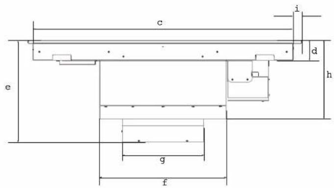
text_image
c i d e h g fPLAN FRONT
text_image
a m j h k lPROFIL
| Modèle Modèle | ||
| ENF430BL ENF436BL | ||
| a 22 | 732" (56.46 cm) | |
| b 30 | 2164" (77.05 cm) 36" | (91.5 cm) |
| c 28 | 1364" (71.64 cm) 34" | (86.39 cm) |
| d 2 | 1732" (6.45 cm) | |
| e 13 | 316" (33.48 cm) | |
| f 16 | 916" (42.1 cm) | |
| g 10 | 58" (27.05 cm) | |
| Modèle Modèle | ||
| ENF430BL ENF436BL | ||
| h 10 | 316'' (25.9 cm) | |
| i 1" (2.56 cm) | ||
| j | 6^13/16'' (17.29 cm) | |
| k | 6^13/32'' (16.33 cm) | |
| l 4 | ^15/_64'' (10.75 cm) | |
| m | ^21/32'' (1.7 cm) | 58'' (1.66 cm) |
ACCESSOIRES ET PIÈCES CONSOMMABLES
text_image
Diagram showing a trash bin with an arrow indicating direction, likely illustrating a disposal or recycling process.IMPORTANT
natural_image
Pure mechanical diagram showing a vertical frame with internal components and an arrow indicating direction (no text or symbols)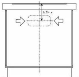
text_image
12.95 cmtext_image
A B C D E F G H Inatural_image
Simple 3D illustration of a rectangular block on a flat base (no text or symbols)natural_image
Isometric illustration of a rectangular block with a magnified inset showing a small 3D section labeled '5mm' (no text or symbols on the main diagram)natural_image
Diagram of a rectangular block with a flat base and an inset showing a mechanical component (no text or symbols)natural_image
Technical line drawing of a mechanical assembly with mounting brackets and a magnified inset showing a component detail (no text or symbols)natural_image
Isometric line drawing of a rectangular frame with a recessed inner square (no text or symbols)natural_image
Illustration of a rectangular electronic component with a magnified inset showing a small cutaway detail (no text or symbols)natural_image
Technical line drawing of a mechanical assembly with no visible text or symbolsnatural_image
Diagram showing a layered structure with an inset close-up of a mechanical component (no text or symbols)natural_image
Diagram showing a layered structure with an inset magnified view of a rectangular component (no text or symbols)text_image
Digital display control interface showing analog clock, lock, and numeric input signals with labeled buttons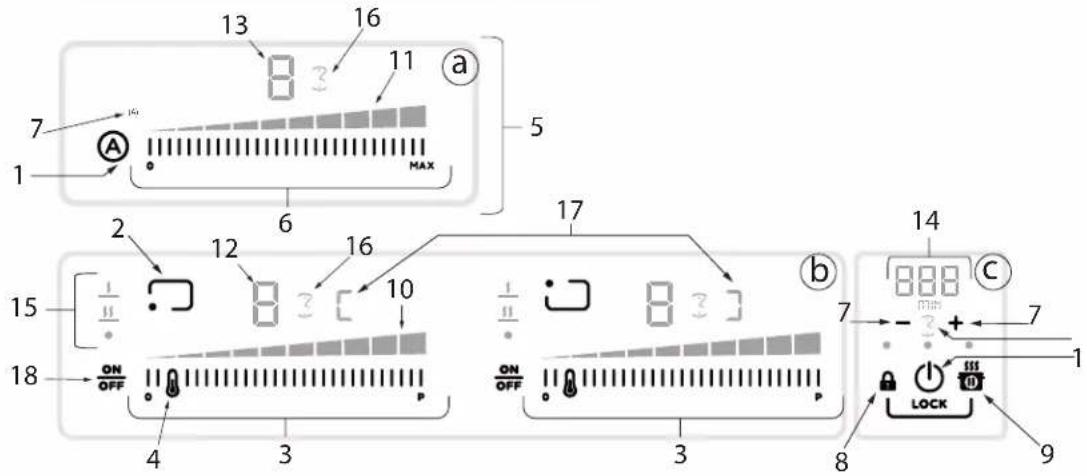
text_image
13 16 11 a 7 1 MAX 5 2 12 16 10 17 15 ON OFF 4 3 3 ON OFF ON OFF 8 14 888 c 7 + - 7 1 LOCK 9Clés Led de dissipation
natural_image
Diagram of a mechanical component with arrows indicating motion or force direction (no text or symbols)text_image
Technical diagram showing a mechanical component with an inset magnified view highlighting a hand gesture.text_image
Diagram showing a mechanical component with an annotation pointing to an icon labeled 'A' and a cursor, likely illustrating a process or assembly.natural_image
Simple line drawing of a cooking pan with a lid and a side table, no text or symbols presentnatural_image
Simple line drawing of a mechanical component with a cross mark and triangular shapes (no text or symbols)text_image
Diagram showing a 3D object with an arrow pointing to a document, accompanied by a circular icon labeled 'A' with a finger pointing at it.text_image
Diagram illustrating smart home control interface with hand, navigation bar, and LCD display showing 'HOOD 3'natural_image
Simple line drawing of a cooking pan with a pot and steam rising (no text or symbols)natural_image
Illustration of kitchen utensils including a flat plate, cooking pan, and three panes with visible contents (no text or symbols)CONTENEURS PRÉEXISTANTS
natural_image
Pure technical line drawing of a mechanical component with no text or symbolsnatural_image
Technical line drawing of a mechanical assembly with two circular insets showing close-up views of internal components (no text or symbols)ENTRETIEN DE NETTOYAGE
text_image
Technical diagram showing a mechanical assembly with three labeled components and an inset view of a component being inserted.RECHERCHE DES PANNES
* National Fire Protection Association Batterymarch Park Quincy, Massachusetts 02269
** CSA International 8501 East Pleasant Valley Road Cleveland, Ohio 44131-5575
ANTES DE INSTALAR
text_image
Warning symbol with exclamation mark and two hands, one white and one gray, indicating hazard or caution.DIMENSIONES DEL PRODUCTO
text_image
b a S = 1 D D C D S = 1.000 - 1.000 - 1.000 - 1.000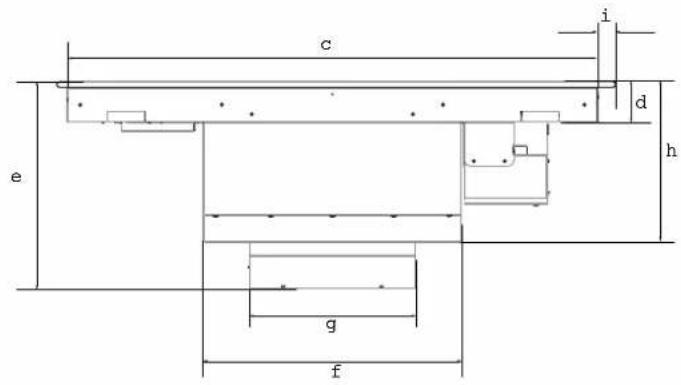
text_image
c i d e h g fPLANO FRONTAL
text_image
a m j h k lPERFIL
| Modelo Modelo | ||
| ENF430BL ENF436BL | ||
| a 22 | 732" (56.46 cm) | |
| b 30 | 2164" (77.05 cm) 36" | (91.5 cm) |
| c 28 | 13164" (71.64 cm) 34" | (86.39 cm) |
| d 2 | 1732" (6.45 cm) | |
| e 13 | 316" (33.48 cm) | |
| f 16 | 916" (42.1 cm) | |
| g 10 | 58" (27.05 cm) | |
| Modelo Modelo | ||
| ENF430BL ENF436BL | ||
| h 10 | 316" (25.9 cm) | |
| i 1" (2.56 cm) | ||
| j | 6^13/16" (17.29 cm) | |
| k | 6^13/32" (16.33 cm) | |
| l 4 | ^15/_64" (10.75 cm) | |
| m | ^21/32" (1.7 cm) | 58" (1.66 cm) |
ACCESSOIRES ET PIÈCES CONSOMMABLES
| KIT | # No. Parte |
| Kit de Ductos | KIT0192361 |
| Kit Filtros de Carbón | KIT0192765 |
INSTALACIÓN
text_image
Diagram showing a trash bin with an arrow indicating direction, likely illustrating a waste sorting or disposal process.IMPORTANTE
natural_image
Pure architectural or mechanical diagram showing a vertical frame with internal components and an arrow indicating direction (no text or symbols)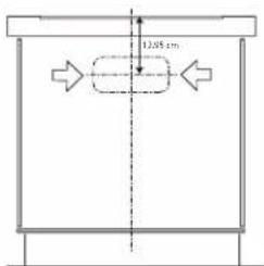
text_image
12.85 cmtext_image
A B C D E F G H Inatural_image
Isometric view of a rectangular block with a flat top and base, no text or symbols present.natural_image
Technical illustration of a rectangular block with an inset showing a small curved component labeled '5mm' (no text or symbols beyond the label)natural_image
Diagram showing a rectangular block with a magnified inset of a mechanical joint detail (no text or symbols)flowchart
graph TD
    A["Vehicle"] --> B["Zoomed Section View"]
    B --> C["Arrow indicating direction"]
    C --> D["Left Side"]
    C --> E["Right Side"]
natural_image
Simple line drawing of a rectangle centered on a vertical axis, with no text or symbols present.
ENCENDIDO