One+ CCG1801MHG - Glue gun RYOBI - Free user manual and instructions
Find the device manual for free One+ CCG1801MHG RYOBI in PDF.
| Product Type | Cordless Glue Gun |
| Brand | RYOBI |
| Model | CCG-1801 (One+ CCG1801MHG) |
| Voltage | 18 V |
| No-load speed (high) | 5.5 mm/s |
| No-load speed (low) | 1 mm/s |
| Sound pressure level | 59 dB(A) (uncertainty K 3 dB) |
| Sound power level | 70 dB(A) (uncertainty K 3 dB) |
| Vibrations (total value) | 2.5 m/s² (uncertainty K 1.5 m/s²) |
| Operating temperature range | 0 °C to 40 °C |
| Storage temperature range | 0 °C to 40 °C |
| Recommended charging temperature range | 10 °C to 38 °C |
| Compatible batteries | RYOBI ONE+ 18 V Lithium-ion and Nickel-Cadmium (models: RB18L13, RB18L15, RB18L15B, RB18L25, RB18L30, RB18L40, RB18L50, RB18L90) |
| Compatible chargers | BCL14181H, BCL14183H, RC18150, RC18627, RC18115, RC18120, RC18118C |
| Intended uses | Filling cracks, filling holes, insulation, adhesive application |
| Safety | Trigger lock, electronic overload protection |
| Maintenance | Clean with a clean cloth; avoid solvents; keep the push rod clean |
| Spare parts and repairability | Only the listed parts can be replaced by the user; other parts by an authorized RYOBI service center |
| Warranty | 24 months from the date of purchase, extendable under conditions |
Frequently Asked Questions - One+ CCG1801MHG RYOBI
User questions about One+ CCG1801MHG RYOBI
0 question about this device. Answer the ones you know or ask your own.
Ask a new question about this device
Download the instructions for your Glue gun in PDF format for free! Find your manual One+ CCG1801MHG - RYOBI and take your electronic device back in hand. On this page are published all the documents necessary for the use of your device. One+ CCG1801MHG by RYOBI.
USER MANUAL One+ CCG1801MHG RYOBI
natural_image
Line drawing of a handheld electric shaver tool with no text or symbols


natural_image
Technical diagram of a mechanical assembly with labeled component 11 and directional arrow (no text or symbols beyond labels)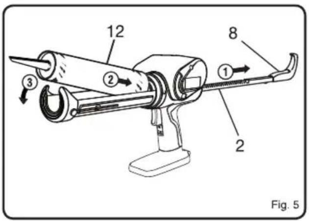
natural_image
Technical diagram of a mechanical device with directional arrows indicating motion or force (no text or symbols present)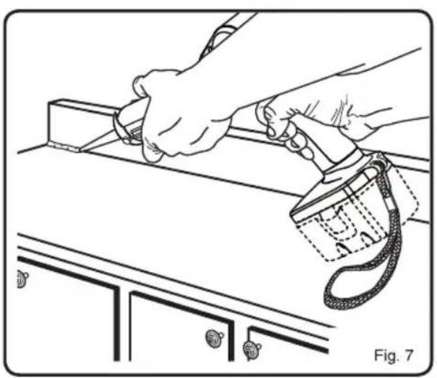
natural_image
Line drawing of a hand using a handheld device to clean or install a cabinet (no text or symbols present)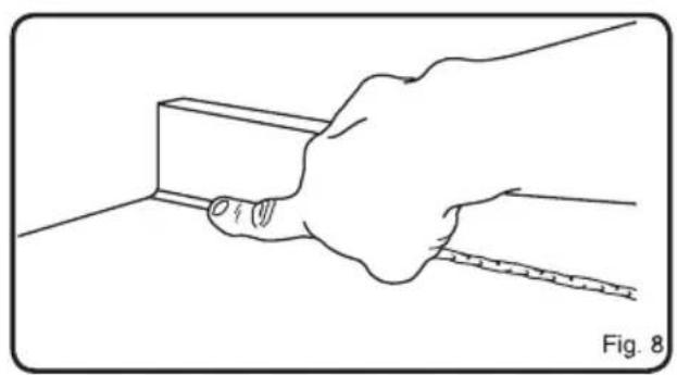
natural_image
Line drawing of a hand using a measuring tool to measure a rectangular object, labeled Fig. 8 (no text or symbols on the diagram itself)| Important! | It is essential that you read the instructions in this manual before assembling, maintaining and operating the product. |
| Attention! | Il est essentiel que vous lisiez les instructions contenues dans ce manuel avant d'assembler, d'entretenir et d'utiliser le produit. |
| Achtung! | Es ist wichtig, dass Sie vor Zusammenbau, Wartung und Benutzung des Produktes die Anweisungen in dieser Anleitung lesen. |
| ¡Atención! | Resulta fundamental que lea este manual de instrucciones antes de realizar el montaje, el mantenimiento y de utilizar este producto |
| Attenzione! | E' importante leggere le istruzioni contenute nel presente manuale prima di montare il prodotto, svolgere le operazioni di manutenzione sullo stesso e metterlo in funzione. |
| Let op! | Het is van essentieel belang dat u de instructies in deze gebruiksaanwijzing leest voor u het product monteert, onderhoudt en gebruikt. |
| Atenção! | É fundamental que leia as instruções deste manual antes da montagem, manutenção e operação do aparelho. |
| OBS! | Det er vigtigt, at man læser instrukserne i denne brugsanvisning, inden man samler, vedligeholder og betjener produktet. |
| Observera! | Det är viktigt att du läser instruktionerna i manualen före montering, användning och underhåll av produkten. |
| Huomio! | On tärkeää, että luet tämän käsikirjan ohjeet ennen tuotteen kokoamista, huoltoa ja käyttöä. |
| Advarsel! | Det er viktig at du leser instruksjonene i denne manualen før sammensetning, vedlikehold og bruk av produktet |
| Внимание! | Необходимо прочитать инструкции в данном руководстве перед сборкой, обслуживанием и эксплуатацией этого изделия. |
| Uwaga! | Koniecznie należy przeczytać instrukcje zawarte w tym podręczniku przed montażem, obsługą oraz konserwacją produktu. |
| Dúležité upozornění! | Neinstalujte, neprovádějte údržbu ani nepoužívejte tento výrobek dříve, než si přečtete pokyny uvedené v tomto návodu. |
| Figyelem! | Fontos, hogy a termék összeszerelése, karbantartása és használata előtt elolvassa a kézikönyvben található utasításokat. |
| Atenție! | Este esențial să citiți instrucțiunile din acest manual înainte de asamblare, efectuarea întreținerii și operarea produsului. |
| Uzmanību! | Ir svarīgi izlasīt šīs rokasgrāmatas instrukcijas pirms uzstādīšanas, apkopes un preces darbināšanas. |
| Dèmesio! | Prieš surenkant, prižiūrint ir naudojant gaminį, būtina perskaityti šiame vadove pateiktus nurodymus. |
| Tähtis! | Enne masina kokkupanekut, hooldamist ja kasutama hakkamist tuleb käesolevas juhendis esitatud juhised kindlasti läbi lugeda. |
| Upozorenje! | Vrlo je važno da ste prije sklapanja, održavanja i rada s ovim proizvodom pročitali upute u ovom priručniku. |
| Pomembno! | Pomembno je da pred montažo vzdrževanjem in uporabo tega izdelka preberete navodila v tem priročniku. |
| Upzornenie! | Je dôležité, aby ste si pred montázou, údržbou a obsluhou produktu prečitali pokyny v tomto návode. |
| Bажно! | Изключително важно е да прочетете инструкциите в настоящото ръководство, преди да преминете към сглобяване, поддръжка или работа с продукта. |
| Bажливо! | Дуже важливо, щоб ви прочитали інструкції в цьому керівництві перед складанням, обслуговуванням та експлуатацією цієї машини. |
| Dikkat! | Ürünün montajını, bakımını yapmadan ve ürünü çalıştırmadan önce bu kılavuzda yer alan talimatları okumanız önemlidir. |
| Просохн! | Еівали полú σημαντικό να διαβάσετε τις οδηγίες στο παρόν εγχειρίδιο πριν συναρμολογήσετε, συντηρήσετε ή λειτουργήσετε το προϊόν. |
Subject to technical modification | Sous réserve de modifications techniques | Technische Änderungen vorbehalten | Bajo reserva de modificaciones técnicas | Con riserva di eventuali modifiche tecniche | Technische wijzigingen voorbehouden | Com reserva de modificações técnicas | Med forbehold for tekniske ændringer | Med förbehåll för tekniska ändringar | Tekniset muutokset varataan | Med forbehold om tekniske endringer | могут быть внесены технические изменения | Z zastrzeżeniem modyfikacji technicznych | Změny technických údajů vyhrazeny | A můszaki módosítás jogát fenntartjuk | Sub rezerva modificațiilor tehnice | Paturam tiesības mainīt tehniskos raksturlielumus | Pasiliekant teisę daryti techninius pakeitimus | Tehnilised muudatused võimalikud | Podloæno tehniëkim promjenama | Tehnične spremembe dopuščene | Právo na technické zmeny je vyhradené | Подлежи на технически модификации | Є об'єктом для технічних змін | Teknik değişiklik hakkı saklıdır | Утю тнв єтифúлаξη τεχνικών троттопоїσεων


English
Safety, performance, and dependability have been given top priority in the design of your cordless caulking gun.
INTENDED USE
The product is intended to be used only by adults who have read and understood the instructions and warnings in this manual, and can be considered responsible for their actions.
Sealing cracks to keep your home's conditioned air inside while keeping unconditioned air outside, increasing your home's energy efficiency.
■ Filling holes and cracks before painting.
■ Creating a moisture barrier around areas that could be damaged by water.
■ Sealing cracks to keep insects from crawling inside your home.
■ Applying adhesive.
Do not use the product in any way other than those stated for intended use.
WARNING
Read all safety warnings, instructions, illustrations and specifications provided with this power tool.
Failure to follow all instructions listed below may result in electric shock, fire and/or serious injury.
Save all warnings and instructions for future reference.
CAULKING GUN SAFETY WARNINGS
- Hold power tool by insulated gripping surfaces, when performing an operation where the cutting accessory may contact hidden wiring. Cutting accessory contacting a "live" wire may make exposed metal parts of the power tool "live" and could give the operator an electric shock.
■ Ambient temperature range for tool during operation is between 0°C and 40°C.
■ Ambient temperature range for tool storage is between 0°C and 40°C.
■ The recommended ambient temperature range for the charging system during charging is between 10°C and 38°C.
ADDITIONAL BATTERY SAFETY WARNINGS
WARNING
To reduce the risk of fire, personal injury, and product damage due to a short circuit, never immerse your tool, battery pack or charger in fluid or allow a fluid to flow inside them. Corrosive or conductive fluids, such as seawater, certain industrial chemicals, and bleach or bleach-containing products, etc., can cause a short circuit.
■ Ambient temperature range for battery during use is between 0°C and 40°C.
■ Ambient temperature range for battery storage is between 0°C and 20°C.
TRANSPORTING LITHIUM BATTERIES
Transport the battery in accordance with local and national provisions and regulations.
Follow all special requirements on packaging and labelling when transporting batteries by a third party. Ensure that no batteries can come in contact with other batteries or conductive materials while in transport by protecting exposed connectors with insulating, non-conductive caps or tape. Do not transport batteries that are cracked or leaking. Check with the forwarding company for further advice.
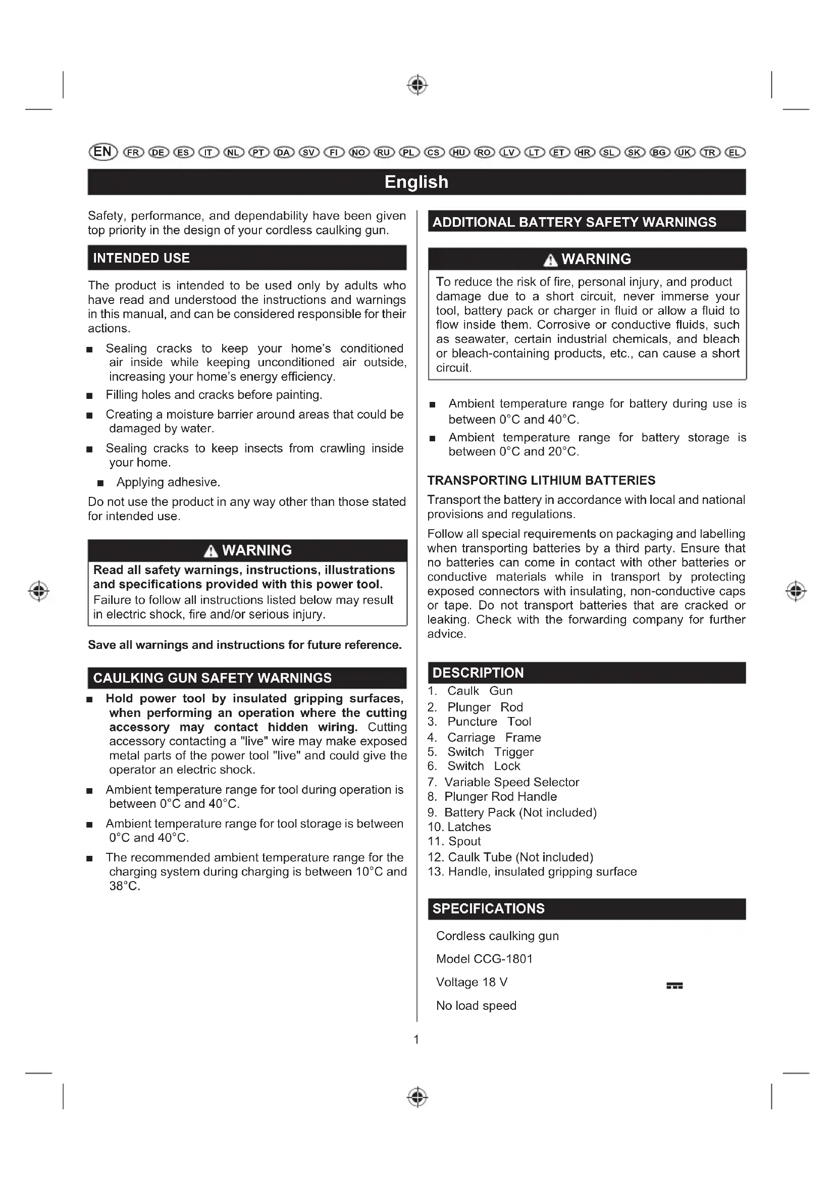
DESCRIPTION
- Caulk Gun
- Plunger Rod
- Puncture Tool
- Carriage Frame
- Switch Trigger
- Switch Lock
- Variable Speed Selector
- Plunger Rod Handle
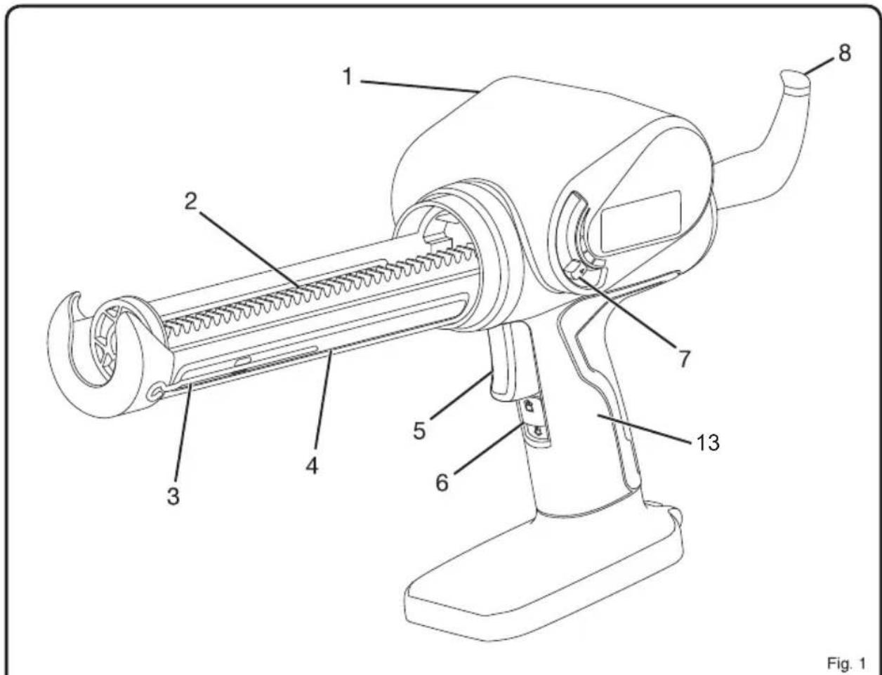
- Battery Pack (Not included)
- Latches
- Spout
- Caulk Tube (Not included)
- Handle, insulated gripping surface
SPECIFICATIONS
Cordless caulking gun
Model CCG-1801
Voltage 18 V
No load speed
English
High 5,5 mm/s
Low 1 mm/s
Measured sound values determined according to EN 62841:
A-weighted sound pressure level Lp = 59 dB(A)
Uncertainty K 3 dB (A)
A-weighted sound power level LW = 70 dB(A)
Uncertainty K 3 dB (A)
Wear ear protectors.
Weighted root mean
The vibration total values(triax vector sum) determined according to EN 62841:
Vibration emission value not exceed 2,5 m/s ^4
Uncertainty K 1,5 m/s 2
| MODEL | BATTERY PACK (not included) | COMPATIBLE CHARGER (not included) |
| Lithium-ion | RB18L13 RB18L15 RB18L15B RB18L25 RB18L30 RB18L40 RB18L50 RB18L90 | BCL14181H BCL14183H RC18150 RC18627 RC18115 RC18120 RC18118C |
OPERATION
WARNING
Do not allow familiarity with products to make you careless. Remember that a careless fraction of a second is sufficient to inflict serious injury.
WARNING
Always wear safety goggles or safety glasses with side shields when operating products. Failure to do so could result in objects being thrown into your eyes, resulting in possible serious injury.
WARNING
Do not use any attachments or accessories not recommended by the manufacturer of this product. The use of attachments or accessories not recommended can result in serious personal injury.
This product will accept RYOBI ONE+ 18 V lithium-ion battery packs and RYOBI ONE+ 18 V nickel-cadmium battery packs.
WARNING
Always remove battery pack from the product when you are assembling parts, making adjustments, cleaning, or when it is not in use. Removing battery pack will prevent accidental starting that could cause serious personal injury.
BATTERY PROTECTION FEATURES
RYOBI 18 V lithium-ion batteries are designed with features that protect the lithium-ion cells and maximize battery life. Under some operating conditions, these built-in features may cause the battery and the tool it is powering to act differently from nickel-cadmium batteries.
During some applications, the battery electronics may signal the battery to shut down, and cause the tool to stop running. To reset the battery and tool, release the trigger and resume normal operation.
NOTE: To prevent further shut down of the battery, avoid forcing the tool.
If releasing the trigger does not reset the battery and tool, the battery pack is depleted. If depleted, the battery pack will begin charging when placed on the lithium-ion charger.
TO INSTALL BATTERY PACK (NOT INCLUDED)
See figure 2.
■ Lock the switch trigger by sliding the switch lock up.
■ Place the battery pack on the tool.
■ Make sure the latches on each side of the battery pack snap into place and the battery pack is secured on the tool before beginning operation.
CAUTION
When placing battery pack in the tool, be sure raised rib on battery pack aligns with the bottom of the drill and latches into place properly. Improper installation of the battery pack can cause damage to internal components.
English
TO REMOVE BATTERY PACK (NOT INCLUDED)
See figure 2.
■ Lock the switch trigger by sliding the switch lock up.
■ Depress the latches on the side of battery pack.
■ Remove the battery pack from the tool.
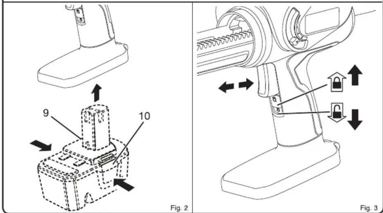
STARTING/STOPPING THE CAULK GUN
See figure 3.
Before attempting to start the caulk gun, be sure the switch lock is in the unlocked position.
■ To turn the caulk gun ON, depress the switch trigger.
■ To turn the caulk gun OFF, release the switch trigger.
LOCKING THE SWITCH TRIGGER
See figure 3.
The switch trigger of the caulk gun can be locked off using the slide switch located below the switch trigger.
■ To lock the switch trigger, slide the switch lock up. This will prevent the caulk gun switch trigger from being depressed.
■ To unlock the switch trigger, slide the switch down. This will allow the caulk gun switch trigger to be depressed.
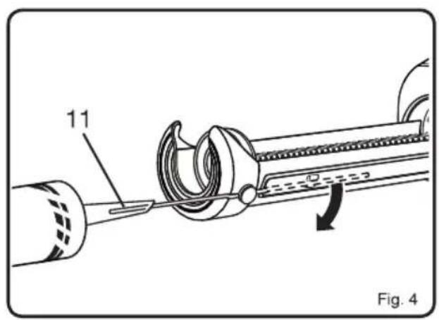
LOADING CAULK (NOT INCLUDED)
See figure 4-5.
Lock the switch trigger by sliding the switch lock up.
■ Using a utility knife, cut off the tip of the spout on a standard 10 oz. tube of caulk. Cut the tip at a 45° angle.
■ Remove as little as possible, taking into consideration the size of the "bead" of caulk you need.
- Check for a second inner seal at the base of the spout. If found, insert the puncture tool inside the spout to break the seal before using. If using a partially filled tube, use the puncture tool to remove any hardened material from the tip.
NOTE: An inner seal is usually found only in cardboard caulk tubes.
■ While holding the caulk gun steady with one hand, pull the handle of the plunger rod away from the caulk gun. Continue pulling until plunger base reaches the back of the carriage frame.
■ Load the caulk tube into the carriage frame, making sure it is well seated at both ends.
ELECTRONIC OVERLOAD PROTECTION
The caulk gun is protected by an electronic overload protection feature. If too much pressure is exerted on the tube, the motor will shut down. This helps to prevent damage to the tool and the caulk tube. If the motor shuts off, make sure that:
■ Nozzle tip is cut
■ Inner seal in the caulk tube is broken
■ Hardened material is removed from the nozzle
■ Caulk tube is not damaged or frozen
■ Plunger rod is free of caulk/adhesive materials
Release the trigger and wait for 3 to 5 seconds to allow the electronics to reset. If the motor again shuts off, move the variable speed selector to the middle position and press the trigger again. If the motor continues to shut off, try another tube of material or take the tool to an authorized service center.
WARNING
Battery tools are always in operating condition. Therefore, switch should always be locked when not in use or carrying at your side.
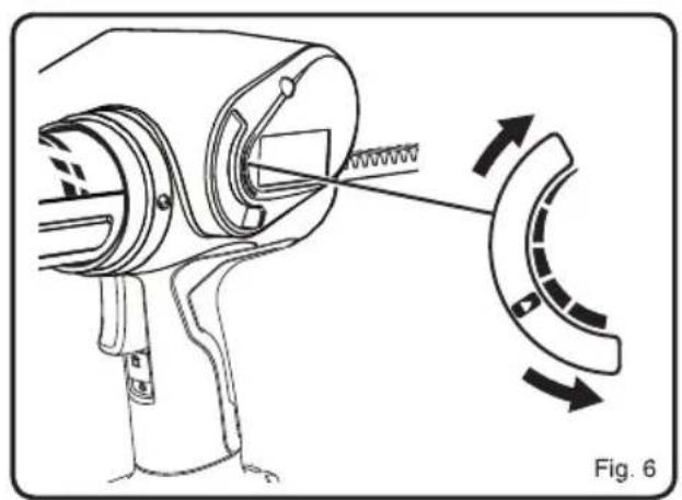
APPLYING CAULK
See figure 6-8.
■ Prepare the surface to be caulked by removing any dust, dirt, or remnants of old caulking. Make sure the area to be caulked is clean and dry.
■ Set the speed of the caulk gun to match your application needs, using just enough caulk to do the job. Experiment in an out-of-the-way area to find the best speed to use to deliver the caulk bead you want.
- Hold the gun at a slight angle. If filling a crack, insert the spout into the crack, if possible; otherwise, run the caulk gun along the surface.
■ Squeeze the trigger on the caulk gun, allowing the caulk to extrude from the tube tip.
NOTE: If the bead of caulk is too narrow, re-cut the nozzle to provide a larger opening. However, it is better to apply a thin bead of caulk and add a little more if necessary than to apply too much and attempt to remove the excess.
- Carefully move the caulk gun at an even pace along the gap to be filled as you continue to depress the switch trigger. Make sure the caulk comes in full contact with both application surfaces. If necessary, use your finger to gently press the caulk into a corner or crack.
NOTE: The best fill is usually achieved by pushing the caulk out into the gap in a forward motion. However, in some cases (particularly where the side materials are rough or uneven), a pulling motion may work better as the cartridge will be less likely to get snagged along the joint.
EN FR DE ES IT NL PT DA SV FI NO RU PL CS HU RO LV LT ET HR SL SK BG UK TR EL
English
■ The motor will shut off automatically when a caulk tube becomes empty. Pull the plunger rod back and replace the caulk tube as necessary.
■ To end the caulk bead, release the switch trigger.
- Draw a moistened finger or other "smoothing tool" along the caulk bead after applying. This will help the caulk adhere to the application surfaces and will create a clean, finished appearance.
■ Use a damp towel or rag to clean off any excess caulk.
MAINTENANCE
WARNING
When servicing, use only original replacement parts. Use of any other parts may create a hazard or cause product damage.
WARNING
Always wear safety goggles or safety glasses with side shields during power tool operation or when blowing dust. If operation is dusty, also wear a dust mask.
WARNING
To avoid serious personal injury, always remove the battery pack from the tool when cleaning or performing any maintenance.
GENERAL MAINTENANCE
Avoid using solvents when cleaning plastic parts. Most plastics are susceptible to damage from various types of commercial solvents and may be damaged by their use. Use clean cloths to remove dirt, dust, oil, grease, etc.
WARNING
Do not at any time let brake fluids, gasoline, petroleum-based products, penetrating oils, etc., come in contact with plastic parts. Chemicals can damage, weaken or destroy plastic which may result in serious personal injury.
To work properly, the plunger rod of the tool must remain clean and free of all caulk and adhesive material. If material does get on the plunger rod mechanism, clean the material off according to the directions of the caulk or adhesive manufacturer.
When the tool is shut off by the electronic overload protection system, always wait for 3 to 5 seconds before depressing the trigger for restart. Frequently depressing
and releasing the trigger under these circumstances may cause interior damage to the caulk gun.
Only the parts shown on the parts list are intended to be repaired or replaced by the customer. All other parts should be replaced at an Authorized Service Center.
ENVIRONMENTAL PROTECTION

Recycle raw materials instead of disposing as waste. The machine, accessories and packaging should be sorted for environmental-friendly recycling.
SYMBOLS

Safety Alert
V Volts
min ^-1

Revolutions or reciprocations per minute
Direct current

EurAsian Conformity Mark

Ukrainian mark of conformity

CE Conformity

Please read the instructions carefully before starting the machine.
Waste electrical products should not be disposed of with household waste. Please recycle where facilities exist. Check with your local authority or retailer for recycling advice.
Français
MISE EN PLACE D'UNE CARTOUCHE (NON FOURNIE)
Voir figure 4-5.
VEILIGHEIDSWAARSCHUWINGEN SPUITKIT
Incerteza K 3 dB (A)
Incerteza K 3 dB (A)
GENERELT VEDLIKEHOLD
| Modelis | CCG-1801 |
| Itampa | 18 V = |
Negotovost K 3 dB (A)
Negotovost K 3 dB (A)
In addition to any statutory rights resulting from the purchase, this product is covered by a warranty as stated below.
- The warranty period is 24 months for consumers and commences on the date the product was purchased. This date has to be documented by an invoice or other proof of purchase. The product is designed and dedicated to consumer and private use only. So there is no warranty provided in case of professional or commercial use. This warranty applies only on new products.
- There is a possibility to extend for a part of the range of power tools (AC/DC) the warranty period over the period described above using the registration on the www.ryobitools.eu website. The eligibility of products for extended warranty is clearly displayed in stores and / or on packaging and is contained within the product documentation. The end user is required to register his/her newly-acquired products online within 30 days from the date of purchase. The end user may register for the extended warranty in his/her country of residence if listed on the online registration form where this option is valid. Furthermore, end users must give their consent to the storage of their personal data that is required to be entered online. They must also accept the terms and conditions. The registration confirmation receipt, which is sent out by e-mail, and the original invoice showing the date of purchase will serve as proof of the extended warranty.
- The warranty covers all defects of the product during the warranty period due to faults in workmanship or material at the purchase date. The warranty is limited to repair and/or replacement and does not include any other obligations including but not limited to incidental or consequential damages. The warranty is not valid if the product has been misused, used contrary to the instruction manual, or has been incorrectly connected to a power supply. This warranty does not apply to:
any damage to the product that is the result of improper or lack of maintenance
–any product that has been altered or modified
– any product where original identification (trade mark, serial number) markings have been defaced, altered or removed
-any damage caused by non-observance of the instruction manual
–any product not displaying the CE approval mark on the rating plate
– any product that has been attempted to be repaired by a non-authorised warranty service centre or without prior authorisation by Techtronic Industries
– any product connected to improper power supply (amps, voltage, frequency)
– any damage caused by external influences (water, chemical, physical, shocks) or foreign substances
-normal wear and tear spare parts
-inappropriate use, overloading of the tool
-use of non-approved accessories or parts
- Power tool accessories provided with the tool or purchased separately, including but not limited to screw driver bits, drill bits, abrasive discs, sand paper and blades, lateral guide, etc.
-
Components (parts and accessories) subject to natural wear and tear, including but not limited to service & maintenance kits, carbon brushes, bearings, chuck, SDS drill bit attachment or reception, power cord, auxiliary handle, transport carry case, sanding plate, dust bag, dust exhaust tube, felt washers, impact wrench pins & springs, etc.
-
For servicing, the product must be sent or presented to a RYOBI authorised service station listed for each country in the following list of service station addresses. In some countries your local RYOBI dealer undertakes to send the product to the RYOBI service organisation. When sending a product to a RYOBI service station, the product should be safely packed without any dangerous contents such as petrol, marked with sender's address and accompanied by a short description of the fault.
- A repair / replacement under this warranty is free of charge. It does not constitute an extension or a new start of the warranty period. Exchanged parts or products become our property. In some countries delivery charges or postage will have to be paid by the sender. Your statutory rights arising from the purchase of the product remain unaffected
- This warranty is valid in the European Community, Switzerland, Iceland, Norway, Liechtenstein, Turkey and Russia. Outside these areas, please contact your authorised RYOBI dealer to determine if another warranty applies.
AUTHORISED SERVICE CENTRE
To find an authorised service centre near you, visit http://uk.ryobitools.eu/header/service-and-support/service-agents.
FR RYOBI® CONDITIONS D'APPLICATION DE LA GARANTIE
EN DECLARATION OF CONFORMITY
Techtronic Industries GmbH
Max-Eyth-Straße 10, 71364 Winnenden, Germany
Herewith we declare that the product
Cordless Caulking Gun
Brand: RYOBI
Model number: CCG-1801
Serial number range: 44404204000001 - 44404204999999
is in conformity with the following European Directives and harmonised standards 2006/42/EC, 2014/30/EU, 2011/65/EU
EN 62841-1:2015, EN 55014-1:2017, EN 55014-2:2015
RoHS documentation is compiled according to EN 50581:2012

Todd Chipner
Sr. Director, CPT Quality and Asia Regulatory & Safety
Winnenden, Dec. 31, 2018
Authorised to compile the technical file:
Alexander Krug, Managing Director
Techtronic Industries GmbH
Max-Eyth-Straße 10, 71364 Winnenden, Germany
FR DÉCLARATION DE CONFORMITÉ
Techtronic Industries GmbH
Max-Eyth-Straße 10, 71364 Winnenden, Germany
Winnenden, Dec. 31, 2018
Max-Eyth-Straße 10, 71364 Winnenden, Germany
Max-Eyth-Straße 10, 71364 Winnenden, Germany
Winnenden, Dec. 31, 2018
Max-Eyth-Straße 10, 71364 Winnenden, Germany

Max-Eyth-Straße 10, 71364 Winnenden, Germany
Winnenden, Dec. 31, 2018
Max-Eyth-Straße 10, 71364 Winnenden, Germany
Max-Eyth-Straße 10, 71364 Winnenden, Germany
Winnenden, Dec. 31, 2018
Max-Eyth-Straße 10, 71364 Winnenden, Germany
NL CONFORMITEITSVERKLARING
Techtronic Industries GmbH
Max-Eyth-Straße 10, 71364 Winnenden, Germany
Winnenden, Dec. 31, 2018
Max-Eyth-Straße 10, 71364 Winnenden, Germany

Max-Eyth-Straße 10, 71364 Winnenden, Germany
Max-Eyth-Straße 10, 71364 Winnenden, Germany
DA OVERENSSTEMMELSESERKLÆRING
Techtronic Industries GmbH
Max-Eyth-Straße 10, 71364 Winnenden, Germany
Vi erklærer hermed, at produktet
Batteridreven Limpistol
Brand: RYOBI
Modelnummer: CCG-1801
Serienummerområde: 44404204000001 - 44404204999999
Winnenden, Dec. 31, 2018
Max-Eyth-Straße 10, 71364 Winnenden, Germany
SV KONFORMITETSDEKLARATION
Techtronic Industries GmbH
Max-Eyth-Straße 10, 71364 Winnenden, Germany
Winnenden, Dec. 31, 2018
Max-Eyth-Straße 10, 71364 Winnenden, Germany
FI SÄÄNNÖSTEN NOUDATTAMINEN
Techtronic Industries GmbH
Max-Eyth-Straße 10, 71364 Winnenden, Germany
Winnenden, Dec. 31, 2018
Max-Eyth-Straße 10, 71364 Winnenden, Germany
NO SAMSVARSERKLÆRING
Techtronic Industries GmbH
Max-Eyth-Straße 10, 71364 Winnenden, Germany
Winnenden, Dec. 31, 2018
Max-Eyth-Straße 10, 71364 Winnenden, Germany
Max-Eyth-Straße 10, 71364 Winnenden, Germany
Winnenden, Dec. 31, 2018
Max-Eyth-Straße 10, 71364 Winnenden, Germany

PL DEKLARACJA ZGODNOŚCI
Techtronic Industries GmbH
Max-Eyth-Straße 10, 71364 Winnenden, Germany
Winnenden, Dec. 31, 2018
Max-Eyth-Straße 10, 71364 Winnenden, Germany
CS PROHLÁŠENÍ O SHODĚ
Techtronic Industries GmbH
Max-Eyth-Straße 10, 71364 Winnenden, Germany
Winnenden, Dec. 31, 2018
Max-Eyth-Straße 10, 71364 Winnenden, Germany
HU MEGFELELŐSÉGI NYILATKOZAT
Techtronic Industries GmbH
Max-Eyth-Straße 10, 71364 Winnenden, Germany
Winnenden, Dec. 31, 2018
Max-Eyth-Straße 10, 71364 Winnenden, Germany
RO DECLARATIE DE CONFORMITATE
Techtronic Industries GmbH
Max-Eyth-Straße 10, 71364 Winnenden, Germany
Alexander Krug, Director General
Techtronic Industries GmbH
Max-Eyth-Straße 10, 71364 Winnenden, Germany
LV ATBILSTĪBAS DEKLARĀCIJA
Techtronic Industries GmbH
Max-Eyth-Straße 10, 71364 Winnenden, Germany
Winnenden, Dec. 31, 2018
Max-Eyth-Straße 10, 71364 Winnenden, Germany
LT ATITIKTIES PAREIŠKIMAS
Techtronic Industries GmbH
Max-Eyth-Straße 10, 71364 Winnenden, Germany
Winnenden, Dec. 31, 2018
Max-Eyth-Straße 10, 71364 Winnenden, Germany

ET VASTAVUSDEKLARATSIOON
Techtronic Industries GmbH
Max-Eyth-Straße 10, 71364 Winnenden, Germany
Kinnitame, et see toode
Winnenden, Dec. 31, 2018
Max-Eyth-Straße 10, 71364 Winnenden, Germany
HR IZJAVA O USKLAĐENOSTI
Techtronic Industries GmbH
Max-Eyth-Straße 10, 71364 Winnenden, Germany
Winnenden, Dec. 31, 2018
Max-Eyth-Straße 10, 71364 Winnenden, Germany
SL IZJAVA O SKLADNOSTI
Techtronic Industries GmbH
Max-Eyth-Straße 10, 71364 Winnenden, Germany
Winnenden, Dec. 31, 2018
Max-Eyth-Straße 10, 71364 Winnenden, Germany
SK PREHLÁSENIE O ZHODE
Techtronic Industries GmbH
Max-Eyth-Straße 10, 71364 Winnenden, Germany
Winnenden, Dec. 31, 2018
Max-Eyth-Straße 10, 71364 Winnenden, Germany
Max-Eyth-Straße 10, 71364 Winnenden, Germany
Winnenden, Dec. 31, 2018
Max-Eyth-Straße 10, 71364 Winnenden, Germany
Max-Eyth-Straße 10, 71364 Winnenden, Germany
Winnenden, Dec. 31, 2018
Max-Eyth-Straße 10, 71364 Winnenden, Germany


UYGUNLUK BEYANI
Techtronic Industries GmbH
Max-Eyth-Straße 10, 71364 Winnenden, Germany
Winnenden, Dec. 31, 2018
Max-Eyth-Straße 10, 71364 Winnenden, Germany

ΔΗΛΩΣΗ ΣΥΜΜΟΡΦΩΣΗΣ
Techtronic Industries GmbH
Max-Eyth-Straße 10, 71364 Winnenden, Germany
Winnenden, Dec. 31, 2018
Max-Eyth-Straße 10, 71364 Winnenden, Germany


EN RYOBI is a trademark of Ryobi Limited, and is used under license.
© 2019 Techtronic Cordless GP. All rights reserved.
71364 Winnenden, Germany