USER MANUAL PGKGA 40Li B2 PARKSIDE
natural_image
Disassembled tool set including a diagonal shaver, chain, and mechanical components (no text or symbols visible)

DE AT CH
Translation of the original instructions
NL BE
Tuin-accu-combi-apparaat 40 V
Before reading, unfold the page containing the illustrations and familiarise yourself with all functions of the device.
FR BE
GB / MT Translation of the original instructions Page
Heckenschere ...... ca. 5,0 kg
Trimmer...... ca. 4,3 kg
natural_image
Diagram showing a mechanical joint or fracture with an arrow indicating direction (no text or symbols present)
natural_image
Diagram showing three rectangular blocks with downward arrows indicating flow or movement (no text or symbols)
natural_image
Diagram of a mechanical or electrical component with a tool interacting with a grid-like structure (no text or symbols)
Wartungsintervalle
Intended Use......43
General Description......43
Extentofdelivery 43
Overview....44
Safety features 45
Function Description ....45
Technical Data......45
Chargingtime 46
Notes on Safety 47
Symbols in the manual....47
Symbols on the Equipment .....47
General Notes on Safety......49
General safety instructions for power tools....49
Hedge trimmer safety warnings .....52
Safety information for chainsaws .....53
Kickback causes and how to avoid them with pole-mounted pruners.....54
Safety information for lawn and lawn edge trimmers....55
Brush cutter - kickback causes and how to avoid them with a 3-tooth blade.....57
Additional safety instructions .....57
Assembly....58
Remove/insert battery ....58
Mounting the tubular shaft....58
Mounting the round handle .....58
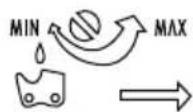
Mounting the saw chain....59
Tensioning the saw chain 59
Mounting the protective cover......60
Removing/mounting the
protective cover extension....60
Initial Operation....60
Chainlubrication 60
Swivelling Out the Blade Beam......61
Pivoting the pole-mounted pruner .....61
Putting on the carrying harness......61
Sliding the carrying eye......62
Assemble the 3-tooth blade....62
Mount the spool....63
Extendthethread 63
Switching on and off 63
Checking the charge status of the batteries 64
Working with the hedge trimmer.....64
Working with the pole-mounted pruner 64
Working using the thread spool ......65
Working with the 3-tooth blade......65
Putting down the device 65
Cutting techniques using the hedge trimmer 65
Cutting techniques using the pole-mounted pruner....66
Working Safely......67
Maintenance/Cleaning ......67
Cleaning......67
Service intervals....68
Service intervals table....68
Sharpening the cutting teeth ......68
Maintaining/turning the blade bar...69
Replacing the spool......69
Sharpen the line cutter......69
Winding up the spool....70
Lubricating the gears 70
Storage....70
Transport 70
Waste Disposal and
Environmental Protection .....71
Guarantee 71
Repair Service....72
Service-Center....72
Importer 73
Spare Parts/Accessories......73
Trouble Shooting....74
Translation of the original
EC declaration of conformity ....425
Exploded Drawing ......437
Introduction
Congratulations on the purchase of your new device. With it, you have chosen a high quality product.
During production, this equipment has been checked for quality and subjected to a final inspection. The functionality of your equipment is therefore guaranteed. It cannot be ruled out that residual quantities of lubricants will remain on or in the equipment in isolated cases. This is not a fault or defect and it represents no cause for concern.

The operating instructions constitute part of this product. They contain important information on safety, use and disposal. Before using the product, familiarise yourself with all of the operating and safety instructions. Use the product only as described and for the applications specified. Keep this manual safely and in the event that the product is passed on, hand over all documents to the third party.
Intended Use
With the hedge trimmer attachment, this device is intended for cutting and trimming hedges, bushes and ornamental shrubs. The pole-mounted pruner attachment is intended for trimming large branches and limbs. The trimmer and 3-tooth blade attachment is intended for cutting grass in the garden, along flower beds, around trees or fence posts, and light under-growth. The device is intended for use in residential applications.
This device is not intended for commercial use. Commercial use will invalidate the guarantee. Any other use that is not expressly permitted in these instructions may result in damage to the device and pose a serious hazard to the user.
The equipment is designed for use by adults. Adolescents over the age of 16 may use the device only under supervision. Local regulations may specify an age limit for the user. Do not use the device in the rain. The operator or user is responsible for accidents or damage to other people or their property.
The manufacturer is not liable for damages caused by unspecified use or incorrect operation.
The device is part of the Parkside X 20 V TEAM series and can be operated using Parkside X 20 V TEAM series batteries. The batteries may only be charged using chargers from the Parkside X 20 V TEAM series.
General Description
The illustration of the principal functioning parts can be found on the front and back foldout pages.
Extent of delivery
- Motor unit
- Hedge trimmer attachment with protective cover
- Pole-mounted pruner attachment with protective cover
- Trimmer attachment with spool and 3-tooth blade
- Carrying harness
- Round handle
- 2 x hexagon socket wrench (AF 4 mm, AF 5 mm)
- Mounting key (AF 13 mm, AF 19 mm)
- Phillips screwdriver (useable on both sides)
- Oil bottle
- Assembly materials
- Operating instructions
GB MT

The Allen key (AF 4 mm) is stored in the device housing on delivery.

Battery and charger are not included.
Overview

1 Saw chain
2 Front tubular shaft
3 Wing nut
4 Tubular shaft on the appliance housing
5 Round handle, front handgrip
6 Carrying eye
7 Leg protection
8 Lock, tubular shaft
9 Transport protection cap, saw chain
10 Transport protection cap, cutter bar
11 Cutter bar
12 3-tooth blade
13 Transport protection, 3-tooth blade
14 Protective cover
15 Thread cutter
16 Extension, protective cover
17 Spool cap
18 Saw chain oil
19 Carrying harness
20 Body protection
21 Hexagon socket wrench (AF 4 mm)
22 Hexagon socket wrench (AF 5 mm)
23 Mounting key
(AF 13 mm, AF 19 mm)
24 Phillips screwdriver/slotted screwdriver
25 Rechargeable battery
26 Charger
27 Battery charge level indicator
28 Button for charge level indicator
29 Safety switch
30 On/off switch
31 Hexagon socket wrench storage

32 Star grip screw, round handle assembly

33 Chain wheel cover
34 Nut, chain wheel cover
35 Blade bar
36 Chain sprocket
37 Bar bolt
38 Chain tensioning screw

39 Oil tank
40 "MIN" marking, oil level indicator
41 Oil tank cover
42 Adjusting screw, oil feed

43 Handle, cutter bar adjustment
44 Safety lever, cutter bar
45 Lock lever, cutter bar

46 Lock, pole-mounted pruner

47 Lug, quick-release device
48 Screw, carrying eye

49 Phillips screwdriver, protective cover
50 Cover, protective cover
51 Screws, cover

52 Mounting spindle
53 Washer
54 Conical spring washer
55 Nut

56 Click lock
57 Spool
58 Thread outlet eye
M 59 Notch, spool
60 Groove, spool
D 61 Oil passage
N 62 Lubrication nipple, pole-mounted pruner
63 Screw, gear lubrication
Safety features
29 Safety switch
The switch lock must be unlocked in order to switch on the device.
30 Start switch
The device switches off immediately once the start switch is released.
19 Carrying harness
Ensures the load is evenly spread across the shoulders, back, hips and thighs.
Function Description
The device is powered by an electric motor. The device is equipped with a hedge trimming attachment (with safety cutter bars), a pole-mounted pruning attachment (with blade and saw chain) and a lawn trimming attachment (with thread spool or 3-tooth blade). The device can only be operated whilst the safety switch is pressed to protect the user. Please refer to the descriptions below for information on how the operating elements work.
Technical Data
Motor voltage U .....40 V== (2 x 20 V)
Current strength I 16 A
Motor idle speed n_0 .....7500 rpm
Protection type.....IPXO
Weight, motor unit 2.3 kg
Weight (operationally ready)
Pole-mounted pruner .....ca. 4.5 kg
Hedge trimmer ...... ca. 5.0 kg
Trimmer ca. 4.3 kg
Brush cutter ...... ca. 4.3 kg
Hedge trimmer
Cutting length....410 mm
Max. recommended
branch thickness 15 mm
Idle speed (without load) n_0 ....1200 rpm
Cuts/min....2400
Vibration on handgrip
(a_h) 3.690 m/s²; K=1.5 m/s²
Vibration on round handle
(a_h) 4.320 m/s ^2 ; K= 1.5 m/s ^2
Sound pressure level
(L_pA) 86.3 dB(A); K_pA = 3 dB
Sound power level ( L_WA )
measured 100.9 dB(A), K_WA = 1.97 dB
guaranteed 106 dB(A)
Pole-mounted pruner
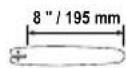
Blade .... Trilink 8" - M1430833-1041TL
Blade length....8"/195mm
Cutting length......approx. 180 mm
Sprocket teeth 5
Chain ..... Trilink 8" - CL14333TL
Chain thickness 1.1 mm
Chain speed v_0 ......max. 10 m/s
Oil tank volume ...... 160 cm ^3 / 160 ml
Vibration on handgrip
(a_h) 3.690 m/s²; K=1.5 m/s²
Vibration on round handle
(a_h) 4.320 m/s ^2 ; K= 1.5 m/s ^3
Sound pressure level
(L_pA) 87.1 dB(A); K_pA = 3 dB
Sound power level (LWA)
measured.101.5 dB(A), K_WA = 2,38 dB
guaranteed 106 dB(A)
Trimmer
Cutting diameter,
spool....30 cm / 300 mm
String thickness....2.4 mm
String length....5 m
Speed, spool n 7000 rpm
Max. speed, spool n_max .....13300 rpm
Vibration on handgrip
(a_h) 3.690 m/s²; K= 1.5 m/s²
Vibration on round handle
(a_h) 4.320 m/s ^2 ; K= 1.5 m/s ^2
Sound pressure level
(L_pA) 82 dB(A); K_pA = 3 dB
Sound power level ( L_WA )
measured..93.6 dB(A), K_WA = 2.24 dB
guaranteed 96 dB(A)
Brush cutter
Cutting diameter, 3-tooth blade 25.4 cm
Speed, blade n....7300 rpm
Max. speed, blade n_max ..... 10000 rpm
Vibration on handgrip
(a_h) 3.690 m/s²; K= 1,5 m/s²
Vibration on round handle
(a_h) 4.320 m/s²; K=1,5 m/§
Sound pressure level
(L_pA) 82 dB(A); K_pA = 3 dB
Sound power level ( L_WA )
measured..93.6 dB(A), K_WA = 2.24 dB
guaranteed 96 dB(A)
Noise and vibration values have been determined according to the standards and regulations mentioned in the declaration of conformity.
The stated vibration emission value was measured in accordance with a standard testing procedure and may be used to compare one power tool to another.
The stated vibration emission value may also be used for a preliminary exposure assessment.
Warning: The vibration emission value may differ during actual use of the power tool from the stated value depending on the manner in which the power tool is used.
Try to keep the exposure to vibrations as low as possible. Examples of measures to reduce vibration exposure are the wearing of gloves when using the tool and limiting the working hours. For this purpose all parts of the operating cycle have to be considered (for example, times when the electric tool is switched off and times when it is switched on but running without any load).
Charging time
The device is part of the Parkside X 20 V TEAM series and can be operated with batteries of the Parkside X 20 V TEAM series.
Batteries of the Parkside X 20 V TEAM series may only be charged using chargers of the Parkside X 20 V TEAM series.
We recommend that you operate this appliance with the following batteries only: PAP 20 B1, PAP 20 B3
We recommend charging these batteries with the following chargers: PLG 20 A3, PLG 20 A4, PLG 20 C1, PDSLG 20 A1
An up-to-date list of battery compatibility can be found at:
www.lidl.de/akku
| Charging time (min) | PAP 20 A1 PAP 20 B1 | PAP 20 A2 | PAP 20 A3 PAP 20 B3 | Smart PAPS 204 A1 | Smart PAPS 208 A1 |
| PLG 20 A1 PLG 20 A4 PLG 20 C1 | 60 90 | 120 120 210 | | | |
| PLG 20 A2 45 | 60 80 80 | 165 | | | |
| PLG 20 A3 PLG 20 C3 | 35 45 | 60 50 120 | | | |
| PDSLG 20 A1 3 | 5 45 60 50 | 120 | | | |
| Smart PLGS 2012 A1 | 35 40 | 40 40 50 | | | |
Notes on Safety
This section describes the basic safety rules when working with the device.
This device must not be used by children. Children should be supervised to ensure that they do not play with the device. Cleaning and maintenance must not be carried out by children.
The device must not be used by persons with impaired physical, sensory or mental capabilities, or anyone who does not have sufficient experience or knowledge.
Symbols in the manual


Instruction symbols with information on preventing damage.

Wear cut-resistant gloves.

Help symbols with information on improving tool handling.
Symbols on the Equipment

This device is part of the Parkside X 20 V TEAM series

Caution!

Read through the instruction manual carefully.


Wear safety goggles!


Wear hearing protection!

Wear a safety helmet!

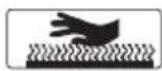
Wear cut-resistant gloves.

Wear cut-resistant work clothing.

Wear anti-slip safety shoes.

Do not leave long hair uncovered. Keep hair away from moving parts.

Keep the equipment away from nearby people.

Do not use the device in the rain or on wet hedges.

GB MT
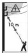
Danger of death by electro-
cution!
Keep at least 10m away from
power lines.

Caution! Falling objects. Particularly when cutting overhead.

Caution! Risk of injury from blades in operation.

Danger due to ejected parts!
Keep other people away.

Attention! Kickback - be aware that you may experience kickback while working with the machine.

Danger due to ejected parts!
Keep other people away.
Caution! Hot surface.
Risk of burns.
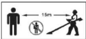
Maintain a safe distance of at least 15 m from other people.

Remove the battery before maintenance work.

Information of the acoustic power level L_WA in dB. (hedge trimmer attachment)

Information of the acoustic power level L_WA in dB.
(pole-mounted pruner attachment)

Information of the acoustic power level L_wA in dB.
(Trimmer and 3-tooth blade)

Machines are not to be place with domestic waste.

Cutting length
Blade bar length

Cutting diameter (spool)
30 cm

Cutting diameter (3-tooth blade)

Battery charge level indicator

Direction of rotation, nut, chain wheel cover
Chain lubrication
Direction of rotation,
screw

Chain oil
Attaching the additional handle
Direction of travel,
saw chain

Direction of travel, spool
General Notes on Safety

Before working with the equipment, familiarise yourself with all operating components. Practice handling the equipment and have the function, operation and working methods explained to you by an experienced user or specialist. Ensure that you can shut off the equipment immediately in an emergency. Inappropriate use of the device may result in serious injury.
In the case of an accident or malfunction during operation, the device must be switched off immediately and the battery removed. Treat injuries appropriately or consult a doctor. For the correction of faults, read the "Troubleshooting" chapter or contact our service centre.

RESIDUAL RISKS
Even if properly operating and handling this electric tool, some residual risks will remain. Due to its construction and build, this electric tool may present the following hazards:
a) Cuts
b) Ear damage if working without ear protection.
c) Damage to your health caused by swinging your hands and arms when operating the appliance for longer periods of time or if the unit is not held or maintained properly.

WARNING! Read all safety directions and instructions.
Omissions in the compliance with safety directions and instructions can cause electrical shock, fire and/or severe injuries.
Retain all safety directions and instructions for future use.
The term "Power Tools" used in the safety instructions refers to mains-operated power tools (with power cord) and to battery-operated power tools (without power cord).
1) Work area safety
a) Keep work area clean and well lit. Cluttered or dark areas invite accidents.
b) Do not operate power tools in explosive atmospheres, such as in the presence of flammable liquids, gases or dust. Power tools create sparks which may ignite the dust or fumes.
c) Keep children and bystanders away while operating a power tool. Distractions can cause you to lose control.
2) Electrical safety

Caution: This is how to avoid accidents and injuries by an electric shock:
a) Power tool plugs must match the outlet. Never modify the plug in any way. Do not use any adapter plugs with earthed (grounded) power tools. Unmodi-
GB MT
fied plugs and matching outlets will reduce risk of electric shock
b) Avoid body contact with earthed or grounded surfaces, such as pipes, radiators, ranges and refrigerators. There is an increased risk of electric shock if your body is earthed or grounded.
c) Do not expose power tools to rain or wet conditions. Water entering a power tool will increase the risk of electric shock.
d) Do not abuse the cord. Never use the cord for carrying, pulling or unplugging the power tool. Keep cord away from heat, oil, sharp edges or moving parts.
Damaged or entangled cords increase the risk of electric shock.
e) When operating a power tool outdoors, use an extension cord suitable for outdoor use. Use of a cord suitable for outdoor use reduces the risk of electric shock.
f) If operating a power tool in a damp location is unavoidable, use a residual current device (RCD) protected supply. Use of an RCD reduces the risk of electric shock.
3) Personal safety

Caution: This is how to avoid accidents and injuries:
a) Stay alert, watch what you are doing and use common sense when operating a power tool. Do not use a power tool while you are tired or under the influence of drugs, alcohol or medication. A moment of inattention white operating power tools may result in serious personal injury.
b) Use personal protective equipment. Always wear eye protection. Protective equipment such as dust mask, non-skid safety shoes, hard hat, or hearing protection used for appropriate conditions will reduce personal injuries.
c) Avoid starting the device unintentionally. Ensure that the power tool is switched off before you connect it to the power supply and/or before you connect the rechargeable battery, or before picking it up or carrying it. Carrying power tools with your finger on the switch or energising power tools that have the switch on invites accidents.
d) Remove any adjusting key or wrench before turning the power tool on. A wrench or a key left attached to a rotating part of the power tool may result in personal injury.
e) Do not overreach. Keep proper footing and balance at all times.
This enables better control of the power tool in unexpected situations.
f) Dress properly. Do not wear loose clothing or jewellery. Keep your hair, clothing and gloves away from moving parts. Loose clothes, jewellery or long hair can be caught in moving parts.
g) If dust extraction and collection devices can be installed, make sure that these are connected and used correctly. Using a dust collector can reduce hazards caused by dust.
a) Do not force the power tool. Use the correct power tool for your application. The correct power tool will do the job better and safer at the rate for which it was designed.
b) Do not use the power tool if the switch does not turn it on and off. Any power tool that cannot be controlled with the switch is dangerous and must be repaired.
c) Remove the plug from the wall socket and/or remove the rechargeable battery before you change the settings of the device, change accessory parts or put away the device. Such preventive safety measures reduce the risk of starting the power tool accidentally.
d) Store idle power tools out of the reach of children and do not allow persons unfamiliar with the power tool or these instructions to operate the power tool.
Power tools are dangerous in the hands of untrained users.
e) Maintain power tools. Check for misalignment or binding of moving parts, breakage of parts and any other condition that may affect the power tool's operation. If damaged, have the power tool repaired before use. Many accidents are caused by poorly maintained power tools.
f) Keep cutting tools sharp and clean. Properly maintained cutting tools with sharp cutting edges are less likely to bind and are easier to control.
g) Use the power tool, accessories and tool bits etc. in accordance with these instructions, taking into account the working
conditions and the work to be performed. Use of the power tool for operations different from those intended could result in a hazardous situation.
a) Only recharge batteries using chargers recommended by the manufacturer. If a charger that has been designed for a particular type of battery is used to charge other batteries, there is a risk of fire.
b) Only use the battery that is intended in an electric tool. The use of other batteries may create a fire hazard and lead to injury.
c) When not in use, keep batteries away from paper clips, coins, keys, nails, screws or other small metal objects that could cause the contacts to be bridged. A short circuit between battery contacts can result in burns or a fire.
d) When misused, fluid may leak from the battery. Avoid any contact with it. On accidental contact, wash in running water. If the fluid comes into contact with the eyes, seek medical assistance also. Leaking battery fluid can cause skin irritation or burns.
6) Service
a) Have your power tool serviced by a qualified repair person using only identical replacement parts. This will ensure that the safety of the power tool is maintained.
Hedge trimmer safety warnings
Preparation
- THIS HEDGE TRIMMER CAN CAUSE SERIOUS INJURIES! Read the instructions carefully regarding the correct handling, preparation and maintenance, for starting and stopping the hedge trimmer. Familiarise with all controls and the proper use of the hedge trimmer.
- Caution! Notice overhead power lines.
- Use of the hedge trimmer should be avoided when people, especially children, are nearby.
- If the cutting unit contacts a foreign body or if the operating noises increase or the hedge trimmer vibrates with unusually high force, turn off the motor and let the hedge trimmer come to a standstill. Pull the mains plug or remove the battery and take the following measures:
- check for damages;
- check for loose parts and fasten all loose parts;
- replace damaged parts with equivalent parts or have them repaired.
- Wear suitable clothing! Do not wear loose clothing or jewellery that can become jammed in the moving parts. It is recommended that you wear solid gloves, non-slip shoes and protective goggles.
- Warning! Wear hearing and eye protection.
Operation
- Switch the appliance off and remove the mains plug or battery before:
moving. Make sure the switch is off when clearing jammed material. Also remove the plug from the mains socket or remove the rechargeable battery from the device. A moment of inattention while operating the hedge trimmer may result in serious personal injury.
• Children must never use the hedge trimmer.
- While operating the hedge trimmer, always ensure that you have a secure footing.
Maintenance and storage
- If the hedge trimmer is taken out of operation for purposes of maintenance, inspection or storage, turn off the motor, unplug the mains plug or remove the battery and make absolutely sure that all rotating parts have come to a standstill. Let the machine cool down before you check or adjust it, etc.
- Carry the hedge trim-mer by the handle with the cutter blade stopped. When transporting or storing the hedge trimmer always fit the cutting device cover. Proper handling of the hedge trimmer will reduce possible personal injury from the cutter blades.
- Store the hedge trimmer in a place where fuel vapours cannot come into contact with open flames or sparks. Always let the hedge trimmer cool down before you put it into storage.
- When in operation, keep all body parts away from the saw chain. Before you start the saw, ensure that the saw chain is not touching anything. When using a chainsaw, losing concentration for just a moment can lead to clothing or body parts being caught up in the saw chain.
• Always hold the chainsaw with your right hand on the rear handle and left hand on the front handle. Holding the chainsaw the other way around increases the risk of injuries and is not permitted.
- Wear protective goggles and hearing protection. Further protective equipment for the head, hands, legs and feet is required. Appropriate protective clothing reduces the risk of injury from flying chip material and accidental contact with the saw chain.
- Do not use the chainsaw to work on trees. Operating a chainsaw on a tree poses the risk of injury.
- Ensure you are standing firmly and only use the chainsaw if the ground beneath you is solid, secure and even. Slippery ground or unstable surfaces such as on a ladder can lead to loss of balance or loss of control over the chainsaw.
GB MT
- If working on a branch under tension, be aware that it will spring back.
Once the tension in the wood fibres has been released, the branch may hit the user and/or control over the chainsaw may be lost.
- Be particularly careful when cutting brushwood and young trees. The thin material may become caught in the saw chain and hit you or cause you to lose balance.
- Carry the chainsaw by the front handle when it is switched off with the saw chain pointing away from your body. Always place the protective cover onto the chainsaw when transporting or storing it.
Careful handling of the chain-saw reduces the probability of accidentally coming into contact with the running saw chain.
- Observe the instructions for lubrication, chain tensioning and replacing accessories. An improperly tensioned or lubricated chain may rip apart or increase the risk of kickback.
- Keep handles dry, clean and free from oil and grease. Greasy, oily handles are slippery and lead to loss of control.
- Only saw wood. Do not use the chainsaw for unintended applications - example: do not use the chainsaw to saw through
plastic, masonry or construction materials not made from wood. Use of the chainsaw for unintended applications can lead to hazardous situations.
Kickback causes and how to avoid them with pole-mounted pruners
Caution - kickbacks! Be aware that you may experience kickback while working with the device. There is a risk of injury. Kickbacks can be avoided through taking the appropriate care and using the correct sawing technique.
- Kickbacks may occur if the tip of the guide rail touches an object, or if the wood bends and the saw chain gets caught in the cut (see Fig. b).
-
Under some circumstances, contact with tip of the rails can lead to an unexpected backwards reaction movement during which the guide rails move upwards and strike the operator (see Fig. a).
-
If the saw chain becomes stuck along the top edge of the guide rail, the rail can kick back heavily towards to the operator.
- Each of these reactions can lead to you losing control of the saw and potentially being seriously injured. Do not rely exclusively on the safety devices built into the chainsaw. As user of the chain-saw, you should undertake various measures to enable accident- and injury-free working.
A kickback is caused by wrongly or incorrectly operating the electric tool. It can be avoided by suitable cautionary measures, such as described below:
- Hold the saw firmly with both hands with thumbs and fingers surrounding the chainsaw handles. Place your body and arms in a position where you can withstand the kick-back forces. The user will be capable of withstanding the kickback forces if suitable measures are undertaken. Never let go of the chainsaw.
- Avoid an abnormal body posture. This will enable better control over the chainsaw in unforeseen situations.
• Always use the replacement rails and saw chains specified by the manufacturer. Incorrect replacement rails and saw chains can cause the chain to break apart and/or may lead to kickback.
- Comply with the manufacturer's instructions for sharpening and maintaining the saw chain. Depth limiters placed too low increase the potential for kickbacks.
- Do not saw with the tip of the blade bar (see Fig. b). There is a risk of kickback.
- Ensure there are no objects on the ground which could cause you to stumble.
Training
a) Read the instructions carefully. Familiarise yourself with the controls and proper use.
b) Never allow people who are not familiar with the instructions or children to use the machine. Local regulations may specify an age limit for the user.
c) Children, individuals with limited physical, sensory or mental capabilities, as well as those who have insufficient experience or knowledge or are not familiar with the instructions must never be permitted to use the device. Local regulations may specify an age limit for the user.
d) Note that the user is responsible for any accidents or risks to others and their property.
Preparation
a) Before use, check the machine for damaged, missing or incor-
rectly installed safety devices or covers.
b) Never use the device if people – especially children – or pets are nearby.
Operation
a) Always wear eye protection, long trousers and sturdy shoes whenever using the machine.
b) Do not use the machine in poor weather, especially if there is a risk of lightning.
c) Use the machine only in daylight or with good artificial lighting.
d) Never use the machine if the cover or guard is damaged, or without a cover or guard.
e) Only switch on the motor when your hands and feet are out of the range of the cutting unit.
f) Always disconnect the machine from the power supply (i.e. remove the removable battery).
1) whenever leaving the machine unattended,
2) before removing blockages,
3) before checking, cleaning or modifying the machine,
4) after contact with a foreign object,
5) if the machine begins to vibrate in an unusual way. If the device starts to vibrate abnormally strong, an immediate inspection is required.
- search for signs of damage;
- have any necessary repairs carried out on damaged parts;
- make sure that all nuts, bolts and screws are properly tightened.
g) Be careful to avoid injuries to your feet and hands by the cutting unit.
h) Make sure to keep the ventilation openings free of foreign objects.
i) Never replace a non-metallic cutting unit with a metallic cutting unit.
i) Avoid an abnormal body posture, keep your balance at all times and ensure secure footing on slopes.
Walk when holding the device in your hand. Do not run!
k) Never operate the machine with defective guards or covers or without protection or without guards.
I) Warning! Ensure that you do not touch any of the dangerous moving parts before you have removed the rechargeable battery and that the dangerous moving parts have come to a complete standstill.
Maintenance and storage
a) Always disconnect the machine from the power supply (i.e. remove the removable battery) before performing maintenance or cleaning.
b) Only use spare and accessory parts recommended by the manufacturer.
c) Regularly inspect and maintain the machine. Only have maintenance performed by a contract workshop.
d) When the machine is not being used, store it out of the reach of children.
Brush cutter - kickback causes and how to avoid them with a 3-tooth blade

In the event of a kick-
back, the operator will
feel a powerful blow
from the combination
machine. This may lead
to losing control of the
device and serious inju-
ry. You can avoid kick-
backs through caution
and proper technique.
While working with the 3- tooth blade there is a risk of kickback if the blade edge hits an obstacle (stone, wood).
- Hold the device with both hands.
• Make sure there are no obstacles on the ground and do not use the 3-tooth blade near fences, metal posts or similar.
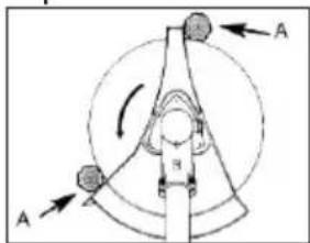
Use only properly sharpened tools. To cut thick stems, switch the device to position A.
Additional safety instructions
- Hold the power tool only by the insulated gripping surfaces as the cutting blade may come into contact with concealed power lines. Contact with a live wire can also cause a charge in metal parts of the appliance and result in an electric shock.
- Carefully inspect the surface to be cut, and remove all wires and other foreign bodies.
- Check the appliance before each use for obvious defects such as loose, worn or damaged parts. Check the appliance for significant damage or defects if it is dropped.
- If the device has been dropped or struck, you must check the device before starting it and ensure it is in a good condition.
- Caution! Local regulations may restrict use of the machine.
• Always maintain the device and cutting tool in a good condition.
- Observe the following: Improper maintenance, the use of non-compliant spare parts or the unauthorised removal or modification of safety equipment can lead to damage to the device and serious injuries to the person working with the device.
- Secure the device well during transport to prevent damage to the device and injuries.
- Before use, check the device for loose fastenings and damaged parts, such as cracks in the cutting attachments.
- Do not use any accessories that are not recommended by PARKSIDE. This can result in electric shock or fire.

Observe the safety information and notes on charging and proper use as shown in the instruction manual for your battery and charger from the Parkside
X 20 V Team series. A detailed description of the charging process and further information can be found in the separate operating instructions.
Assembly

Remove the battery from the device before carrying out any work on the device.

Only use original parts.

The device can be used with either the hedge trimmer, pole-mounted pruner or trimmer attachment, either with spool or 3-tooth blade.

Dismantling is carried out in reverse order.
Remove/insert battery
-
To remove the battery (25) from the device, press the release button on the battery and pull the battery out.
-
To insert the battery (25), push the battery along the guide rail into the device. You will hear it click into place.

Only insert the rechargeable batteries once the device is completely assembled. Risk of injury!

Mounting the tubular shaft

Before mounting, remove the protective cap(s) from the front tubular shaft (2).
- Loosen the wing nut (3).
- Pull the lock (8) outward and turn it left or right as far as it goes.
- Slide the front tubular shaft (2) onto the tubular shaft on the device housing (4).
- Pull the lock (8) outward and turn it back to its original position.
- Turn the front tubular shaft (2) with a gentle rotating movement until the lock (8) clicks into place in the bore on the front tubular shaft (2).
- Fix the tubular shaft in place with the wing nut (3).

Tighten the butterfly screw (3) until no more play is discernible on the front tubular shaft (2)! The use of maximum manual force will damage the tubular shaft.

Mounting the round handle

The round handle must be mounted with a spacing of at least 25 cm to the device handle!

The leg protection must always be mounted on the operator side!
- Loosen the star grip screw (3) and fold the leg protection (7) away.
- Place the round handle (5) onto the tubular shaft of the device housing (4). Choose a position within the levelled adjustment range marked on the bottom of the tubular shaft. The area is marked with a label.
- Close the leg protection (7) and tighten it using the star grip screw (3).

Mounting the saw chain

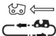
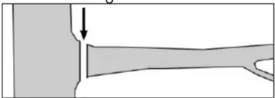
Pay attention to the correct rotation direction of the saw chain. This is indicated on the chain wheel cover (33) and above the bar bolt (37).

Tension the saw chain in accordance with the first 5-6 steps. See section "Tensioning the saw chain".
- Place the device on a level surface.
- Remove the chain wheel cover (33) by loosening the nut (34) with the mounting key (23).
- Place the sawing chain (1) into the blade groove. Place the sawing chain (1) into the chain sprocket (36).
- Place the blade bar (35) and saw chain (1) onto the rail bolts (37). When the nose on the right below the guide bolt (37) sits in the lower round recess on the blade bar, the blade bar is placed correctly. It is normal for the saw chain (1) to sag.
- Pre-tension the saw chain (1) by turning the screw (38) in a clockwise direction with the mounting key (23).
- Put the chain wheel cover (33) back in position. Tighten the chain wheel cover nut (34).

Caution! The pole-mounted pruner can be prone to leaks.
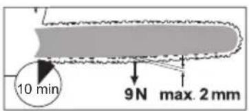
Tensioning the saw chain
Regularly tightening the saw chain provides safety for the user and reduces and/or prevents wear and chain damage. Before starting work and at intervals of approx. 10 minute, we recommend the user to examine the chain tension and correct it if necessary.
The saw chain warms up when working with the saw and thus expands slightly. These „expansions“ can be expected especially from newer saw chains.

Do not re-tension or change the saw chain when it is hot because it shrinks slightly once it has cooled down. If this is not observed it can lead to damage on the guide rail or the motor because the saw chain is now too taut on the blade bar.
Chain tension and chain lubrication have a significant impact on the service life of the saw chain.
The saw chain is properly tensioned when it does not hang from the underside of the blade bar and cannot be moved around by a gloved hand. When pulling on the saw chain with 9 N (approx. 1 kg) of force, the saw chain and blade bar should not be separated by a distance of more than 2 mm.

Risk of injury!
Remove the batteries from
the device before working
on the device.

- Loosen the nut (34) of the sprocket cover (33) with the mounting key (23).
- Tension the saw chain (1) by turning the screw (38) in a clockwise direction with the mounting key (23).
Reduce the saw chain tension by turning the screw anti-clockwise.
- Fix the sprocket cover (33) by tightening the nut (34) with the mounting key (23).

The chain tension of a new saw chain must be readjusted after a maximum of 5 cuts.

Mounting the protective cover
The protective cover (14) must be mounted to the front tubular shaft (2) with the retainer for spool and 3-tooth blade.
-
Screw the protective cover (14) to the front tubular shaft (2) using the two small Phillips screws (49). Use the Phillips screwdriver (24) for this.
-
Fasten the cover (50) to the protective hood (14). Use the hexagon socket wrench (22) and the three screws (51).

Removing/mounting the protective cover extension
If using the 3-tooth blade, the protective cover extension must be removed.
If using the spool, the extension must be mounted.
Removing the protective cover extension:
-
Unlock the lock for the protective cover extension (16) using a slotted screw-driver (24) on the side of the line cutter (15).
-
Remove the protective cover extension (16).
Mounting the protective cover extension:
- Slide the extension (16) onto the protective cover (14). Begin on the side without the string cutter (15).
- Slide the extension (16) up until it clicks into place.
Initial Operation

When working with the device, wear suitable clothing, work gloves, eye protection, protective headgear, hearing protection and cut-resistant work boots. Prior to each use, ensure that the machine is working correctly. Do not lock the On/Off switch in place. Do not use the device if a switch is damaged. Risk of injury and damage to property.

Note noise protection and local specifications. The use of the equipment on certain days (e.g. Sundays and national holidays), at certain times of day (lunch times, night time quiet periods) or in special areas (e.g. health resorts, clinics etc.) is restricted or forbidden.

Chain lubrication

The blade bar and saw chain must never be operated without oil. If the pole-mounted pruner is used with too little oil, the cutting performance and lifespan of the saw chain will decrease as the saw chain will become blunt more quickly. You can identify when there is too little oil if smoke develops or the blade bar changes colour.
The oil flows to the blade bar as soon as the motor starts working.
Filling with chain oil:
- Check the oil level indicator on the oil tank (E 39) regularly and top-up the oil if the minimum mark „MIN“ (E 40) is reached on the oil level indicator. The oil tank holds about 160 ml of oil.
- Use bio-oil containing additives to reduce friction and wear. You can order this from our service centre.
Alternatively, use chain lubricating oil with a low proportion of adhesion additives.
- Empty the oil tank if it will not be used for a prolonged period of time (6-8 weeks).
- Unscrew the oil tank cap (41) and pour the chain oil into the tank.
- Wipe away any spilt oil and close the oil tank cap (41).
- You can regulate the oil flow with the adjusting screw (42).

Always turn off the device and let the motor cool down before filling with chain oil. Overflowing oil can cause a fire.

Swivelling Out the Blade Beam

The blade bar must be checked regularly for wear and reground. A blunt blade bar causes the device to overload. Any damage that results is not covered by the warranty.
- Hold the safety blade beam on the handle to adjust the blade beam (43).
-
Unlock the safety lever (44) and keep it pressed.
-
By simultaneously exerting pressure on the lock lever (45), you will loosen the fixation of the cutter bar.
- The safety blade beam can now be swivelled out. Use the stop stages and allow the stop lever (45) to click back in. The device has 7 possible working positions (+ 1 storage position).
- Then, release the safety lever (44) again and ensure that it latches back into its initial position.

Pivoting the pole-mounted pruner
- Pull the lock (46) outward and turn it 90°.
- Hold the pole-mounted pruner at the protective transport (9) and turn it to the desired position.
There are five possible positions.
- Fix the pole-mounted pruner by pulling the lock (46) outward and turning it 90° back to the original position.

Putting on the carrying harness

The body protection (20) on the carrying harness must be placed between the body and the device.

Always wear the carrying harness when working with the 3-tooth blade! Always turn the device off before taking off the carrying harness. Accident hazard.

Generally, we recommend using the carrying harness whenever using the device.

The harness is equipped with a quick-release lock (47). Squeezing the quick-release lock (47) together releases the device quickly from the harness in a dangerous situation.
- Wear the carrying harness (19) like a backpack. The clip must be situated on the chest.
- Adjust the strap length so that the body protection (20) is level with the hip.
- Open the quick-release lock (47).
- Push open the snap hook.
- Attach the snap hook to the eyelet (6) on the tube shaft of the device.
- Clip the quick-release lock (47) back together with the device.

Place the body protection (20) on your hip between your body and the device.

While wearing the carrying harness, ensure that the pad is placed on your shoulders to increase comfort.

Sliding the carrying eye
Select the appropriate position for the carrying harness eyelet according to whether you are using a spool/3-toothed blade or pruner/hedge trimmer.
You can slide the carrying eye (A 6) to better distribute the weight of the device.
- Loosen the screw (48) on the eyelet (6) for the carrying harness, using the hexagon socket wrench (21) from the storage (A 31).
- Slide the eyelet (6) to the appropriate position.
- Tighten the screw (48) again.
For the trimmer/3-tooth blade operation: Without touching it by hand, the device attached to the harness should
① allow the spool to rest lightly on the ground
② balance the blade approximately 20 cm above the ground.
- Loosen the screw (48) on the carrying harness eye with the hexagon socket wrench (21) and tighten it slightly.
- Depending on the cutting tool, balance the tool according to the criteria mentioned above by moving the eyelet (6) along the tube shaft (4).
- Tighten the screw (48) when the device is in the desired position.

Assemble the 3-tooth blade

Whenever you use the 3-tooth blade, the protective cover without extension must be used. (See Chapter: "Removing/mounting the protective cover extension")
- Remove the rechargeable batteries.
- Place the device on the ground in a stable position.
- Block the mounting spindle (52) using the hexagon socket wrench (22) as depicted.
- Place the 3-toothed blade onto the mounting spindle (52). The blade can be used on both sides.
- Fasten the blade using the thinner washer (53), conical spring washer (54) and nut (55).
Insert the nut (55) into the conical
spring washer (54) as shown.
Use the assembly key (23) to secure it.
- Remove the hexagon socket wrench (22)!

Dismantling is carried out in reverse order.

Mount the spool

The protective cover must be mounted with the extension when using the thread spool.
(See Chapter: "Removing/mounting the protective cover extension")

Do not replace the non-metallic filaments of the spool end with metallic filaments! Risk of injury!
- Remove the rechargeable batteries.
- Place the device on the ground in a stable position.
- Block the mounting spindle (52) using the hexagon socket wrench (22) as depicted.
- Place the thin washer (53) on the mounting spindle (52).
- Screw the spool cap (17) anticlockwise back onto the mounting spindle (52).

Dismantling is carried out in reverse order.
Extend the thread
Your device is equipped with a double-string activated touch control, i.e. the two strings are extended when you tap the cutting head on the ground.
- Hold the device in operation over a grassy area and lightly tap the cutting head a few times on the ground. This causes the thread to lengthen.
- The protective cover (A 15) inserted into the protective cover extension (A 16) cuts the thread to the desired length.
If the thread ends can not be lengthened:
- Turn off the device.
- Press the core insert as far as it will go and pull firmly on the end of the string.
If no line ends are visible:
- Replace the spool (see chapter on 'Replacing the spool').

Attention! Thread remnants can be projected and lead to injuries.

Switching on and off

The charge levels of the inserted batteries do not need to be identical. However, the device will not start if one of the two batteries is exhausted.

Ensure your stance is stable and hold the appliance tightly with both hands and away from your body. Before switching the apparatus on, make sure that it is not touching any objects.
- To start, press and hold the safety switch (29) while pressing the on/off switch (30). You can release the safety switch (29) again.
GB MT

The hedge trimmer and pruner attachment is automatically speed-controlled according to the load condition. When idling without load, the motor speed is lower.
- To turn off, release the on/off switch (30).
Checking the charge status of the batteries
The battery charge level indicator (27) shows the state of charge of the battery (25).
Press the button for the charge level indicator (28) on the device. The charge level of the battery is indicated by illumination of the corresponding LED lights (3 LEDs per charge level indicator).
3 LEDs illuminated (red, orange and green):
Battery charged
2 LEDs illuminated (red and orange):
Battery partially charged
1 LED illuminated (red):
Battery needs to be charged

Charge the battery (25) when only the red LED on the level indicator (27) is illuminated.
Working with the hedge trimmer

While cutting, make sure that you do not touch any objects, such as wire fences or plant supports. This can cause damage to the cutter bar.
- To avoid eye injuries, always wear safety goggles while working with the hedge trimmer.
- Always hold the device tightly with both hands, with one hand on the rear handle and the other hand on the front round handle (A 5).
Your thumb and fingers must tightly clasp the handles.
- Check the carrying harness ( A 19) for comfortable positioning which facilitates holding the hedge trimmer.
- If the blades become jammed with solid objects, switch the device off immediately, pull the mains plug, and remove the object.
- Avoid over-stressing the device while working.
Working with the pole-mounted pruner

If the saw chain gets stuck, do not attempt to pull out the pruner with force. There is a risk of injury. Turn the motor off and use a lever arm or wedge to release the pruner.
- The saw chain should have reached it maximum speed before you begin sawing.
- You will have better control over the device if you saw using the lower edge of the blade bar (saw chain in pulling direction) and not using the upper edge of the blade bar (saw chain in pushing direction).
- The saw chain must not touch the ground or any object while sawing through the material or thereafter.
- Ensure that the saw chain does not get stuck while sawing. The log must not break or splinter.
- Please also observe the precautionary measures to protect against kickback (see the safety information).
- Remove branches hanging downwards by sawing from the top of the branch.
- Twisted branches must be individually cut down to size.
Working using the thread spool
- In small grass areas hold the device at an angle of about 30^ and swing the cutting head evenly to the right and left with a semi-circular movement.
- The best results are obtained with a maximum grass length of 15 cm. If the grass is taller, it is recommended to mow several times.
- To cut around trees, fence posts or other obstacles, slowly move the device around the obstacle and cut with the thread ends.
- Avoid any contact with fixed obstacles (rocks, walls, picket fences, etc.). The thread would wear out quickly. Use the edge of the protective cover to keep the device at the correct distance.

Attention! Do not lay the cutting head on the ground during operation!
Working with the 3-tooth blade

Always wear the harness and suitable protection clothing when working with the device. Wear eye, hearing and head protection.
Ensure that the blade is installed correctly. Replace damaged or blunt tool parts.
There is a risk of injury.

Only use the blade to work on open, even areas. Carefully inspect the area to be cut and remove all foreign bodies. Avoid hitting stones, metal or other obstacles. The blade can be damaged and there is a risk of kickback by the machine.
- When working, hold the cutter above the ground and slowly swivel the device back and forth like a scythe in an equal arch.
- Do not hold the cutting head at an angle.
- Do not use the device to cut wild growth or brushwood.
- Regularly check the blades for damage and replace as needed.
Putting down the device
- Place the device on the ground with the motor housing first.
- The cutting unit (A 1/11/12/17) must be placed on the ground without being subjected to any pressure.
- Do not apply any static pressure whatsoever to the cutting unit (A 1/11/12/17).
Cutting techniques using the hedge trimmer
- Cut thick branches beforehand using a branch clippers.
- The double-sided cutter bar enables cutting in both directions or, with a swinging action, from one side to the other.
- In case of vertical cutting, move the hedge trimmer uniformly forward or up and down in an arc movement.
- In case of horizontal cutting, move the hedge trimmer in a sickle-shaped movement to the edge of the hedge, so that cut branches fall to the ground.
GB MT
- In order to achieve long straight lines, the placing of tensioned guiding cords is recommended.
Cutting Shaped Hedges: It is recommended that hedges be cut in a trapezoidal shape, in order to prevent stripping off of the lower branches. This corresponds to the natural plant growth and allows the hedge to thrive optimally. During cutting, only the new annual growths are reduced and thus a dense branching and a good screen will develop.
- Cut the sides of a hedge first. To do this, move the hedge trimmer in the direction of growth from bottom to top. If you cut down from the top, the thinner branches will move out, which may result in some areas having sparse growth or holes.
- Cut the top edge, according to taste, in a flat shape, roof shape or rounded shape
- Trim young plants to the required shape. The main growth should remain undamaged until the hedge has reached the planned height. All other shoots are lopped off to half size.
Care of Free-Growing Hedges: Free-growing hedges are not shaped when cut, although they must be regularly maintained so the hedge does not become too high.
Cutting techniques using the pole-mounted pruner

Be aware of the risk of kick-back as well as falling branches and branches on the ground.
- Sawing off small branches:
Place the locating surface of the saw against the branch in order to prevent
jerky movements of the saw when you begin to cut it. Guide the saw with light pressure from the top to the bottom through the branch.
Watch out for premature breakage of the branch if you have misjudged the size and weight.
natural_image
Diagram showing a mechanical joint or fracture with an arrow indicating direction (no text or symbols present)
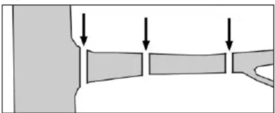
- Sawing off larger branches:
In the case of larger branches, select a relief cut first of all to ensure that the sawing process is controlled. To do this, saw an incision (a) into the bottom third of the branch (with the upper side of the blade). Then saw from top to bottom towards the first cut (with the underside of the blade) (b).

- Sawing in sections:
Saw off large or long branches in sections so that you have control over the place where the branch section lands.
natural_image
Diagram showing three rectangular blocks with downward arrows indicating flow or movement (no text or symbols)
- Saw the lower branches of the tree off first in order to make it easier for the branches that have been cut off to fall to the ground.
- After the cut is completed, the weight of the saw increases abruptly for the operator, as the saw is no longer supported on the branch. There is a danger that you will lose control of the device.
- You should only pull the saw out of the cut with the saw chain running in order to avoid jamming.
- Do not saw with the tip of the cutting equipment.
- Do not saw the bulge at the base of the branch because this will prevent the tree from healing.
Working Safely
- Do not use the high pruning saw when standing on a ladder or in an unsafe position.
- Do not be tempted to make unconsidered cuts. Doing so may endanger both yourself and others.
- Children must be supervised to ensure that they do not play with the equipment.
- Long use of the equipment can result in vibration-related circulatory disorders in the hands. However, the length of use can be extended by using suitable gloves or taking regular breaks. Note that a personal tendency for poor circulation, low outdoor temperatures, or high gripping forces during work will reduce the length of use.
- While using the pole pruner/hedge trimmer, pay attention to the specified working angle of max. 60° in order to ensure that you work safely with the device.
• Always stand on the slope above or to the side of the branch to be sawn.
- Hold the device as close as possible to your body. This will ensure the best balance.
Maintenance/Cleaning

Warning! Risk of injury by dangerous moving parts!

Repair and servicing work not described in this manual should always be carried by our Service Centre. Use only original parts.

Remove the rechargeable battery from the device before cleaning and maintenance.

Wear gloves when working with the blade, saw chain and cutter bar.
Carry out the following maintenance and cleaning work regularly. This will guarantee a long and reliable service life.
- Check the device before each use for obvious defects such as loose, worn or damaged parts. Ensure that the screws are firmly in place.
- Do not cut with blunt or worn blades or chains as otherwise you will overload the motor and gears of your device.
- Check coverings and safety devices for damage and correct seating. Replace these where necessary.
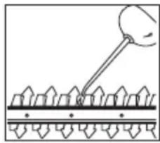
Cleaning

Remove the rechargeable battery from the device before cleaning.
- Clean the appliance after each use. Clean the motor housing with a damp cloth or a brush. The device must neither be sprayed with water nor be put into water.
GB MT
- Keep the ventilation channels of the device clean. Use a damp cloth or brush to do this.
-
Do not use any cleaning agents or solvents. This could damage the device irreparably. Chemical substances may attack the plastic parts of the device.
• Always keep the device clean. After each use of the device, you must
-
clean the blade (with an oily cloth);
- oil the cutter bar with an oil can/spray.
natural_image
Diagram showing a droplet interacting with a surface, no text or symbols present
Service intervals table
| Machine part Action Before each use After 10 hrs of use | | |
| Complete machine | Check condition, replace damaged parts as needed | √ | |
| Accessible screws and nuts | Tighten | √ | |
| Chain wheel Check, replace as needed | √ | |
| Saw chain Check, apply oil, reground or replace | √ | |
| Blade bar Check, rotate, clean, apply oil | √ | √ |
| Cutter head | Check correct installation | √ | |
| Gears | lubricating | | √ |
Sharpening the cutting teeth
Have the saw chain sharpened by a specialist, or proceed in accordance with the operating manual for your saw chain sharpening device. Sharpening a saw chain requires some practice. Replacing the saw chain is preferable in case of doubt.
Service intervals
Carefully perform the maintenance tasks listed in the following table on a regular basis. Regular servicing of your unit will extend the life of your equipment.
Additionally, you will achieve optimum cutting performance and prevent accidents.
Changing the saw chain

Never attach a new saw chain onto worn teeth, or onto a damaged or worn blade bar.
- Switch off the device and remove the batteries.
- Release the nut (D 34) and remove the chain wheel cover (D 33).
- Remove the old saw chain (A 1).
The mounting and tensioning of the new saw chain is described in the "Assembly - Tensioning the saw chain" section.
D Maintaining/turning the blade bar
The blade bar has to be reversed every 8-10 operational hours in order to ensure even wear.
- Switch off the device and remove the batteries from the device.
- Release the nut (34) and remove the sprocket cover (33). Remove the saw chain (1) and the blade bar (35).
- Check the blade bar (D 35) for wear. Remove burrs and straighten the guide surfaces with a flat file.
- Clean the oil passage (D 61) to ensure fault-free, automatic oiling of the saw chain during operation.
- Turn the blade bar (35) once along its horizontal axis.
- Place the saw chain (1) into the blade groove. Place the saw chain (1) into the chain sprocket (36).
- Place the blade (35) and saw chain (1) on the coach screws (37). When the nose on the right below the coach screw (37) sits in the lower round recess on the blade bar, the blade bar is placed correctly. It is normal for the saw chain (1) to sag.
- Pre-tension the saw chain (1) by turning the screw (38) to tension the chain in a clockwise direction. Also see section "Tensioning the saw chain".
- Place the sprocket cover (33) into position. Tighten the nut (34) of the socket cover.
J Replacing the spool
-
Remove the rechargeable batteries.
-
Place the device on the ground in a stable position.
-
Block the mounting spindle (K 52) using the hexagon socket wrench (K 22) as depicted.
Screw the spool cap (17) clockwise to the mounting spindle (52).
-
Open the spool cap (17) by firmly pressing the quick-release catch (56) inwards on both sides of the spool cap (17), and remove the spool cap cover.
-
Place the new spool (57) into the spool cap cover (17) and insert the two ends of the thread through the thread outlets (58). Loosen the two thread ends from the grooves (M 60) on the spool.
-
Place the spool (57) inside the lid of the spool cap (17) and reassemble the lid and base.
-
Screw the spool cap (17) anticlockwise back onto the mounting spindle (K 52). Remove the hexagon socket wrench (K22).
-
Trim the thread line to approx. 15 cm.
L Sharpen the line cutter

Never use the device without a string cutter or defective line cutter. There is a risk of injury. If the thread trimming blade is damaged, be sure to contact our service centre.

Wear protective gloves in order to avoid cutting yourself.
- Switch off the engine and remove the batteries.
- Screw off the line cutter (15) from the protective cover extension (16).
-
Clamp the line cutter (15) in a vice and sharpen the knife with a flat file. File carefully, and always in one direction only.
-
Screw the line cutter (15) back onto the protective cover extension (16).
M Winding up the spool
As an alternative to a new thread spool, you can purchase a 2.4 mm-thick, 5 m-long nylon thread in specialist shops and wind this yourself onto the thread spool.
- Fold the thread in the middle and place the middle of the thread in the notch (59) of the spool (17).
Wind up the two ends in the direction of the arrow, which is shown on the topside of the spool.
- Then clamp the end of each thread in one of the grooves (60) on the spool (17).
N Lubricating the gears
The gear units of the attachments require lubrication after around 10 hours of operation.
Pole pruner
- Use the lubricating nipple (62) to press up to 5 g of standard grease into the gearbox housing with a grease gun.
Trimmer/brush cutter
- Release the screw (63) on the gears.
- Insert up to 5 g of commercially-available lubricating grease into the lubrication opening on the gearbox housing.
- Close the gears again using the screw (63).
Storage

Perform cleaning and maintenance work before storage.
- Store the device in the transport protection (A 9/10) provided in a dry
location and out of reach of children. Store the appliance in horizontal position or secured against toppling over.
- Store the 3-tooth blade (A 12) with the supplied transport protection (A 13) attached.
- For storage, you can hang the unit at the bottom of the motor unit.
- Empty the oil tank if it will not be used for a prolonged period of time (6-8 weeks).
- Clean the device and accessories carefully before storage.
- Store the device in a dry and dustproof location and out of reach of children.
- Do not wrap the device in plastic bags as moisture and mildew may form.
- Do not lie the device down on the protective cover.
Transport

Never transport your appli- ance while the appliance is turned on! Risk of injury!
• Always use the protective cover (A 9/10) when transporting.
- Always carry the device with the cutting unit pointing backwards using both hands: one on the rear handle and the other on the front round handle (A 5).
Waste Disposal and Environmental Protection
Remove the batteries from the device and recycle the device, battery, accessories and packaging in an environmentally-friendly manner.
Do not dispose of waste oil in the sewer or your drain system. Dispose of waste oil in an environmentally friendly way - take it to your local recycling centre.

Electrical machines do not belong in domestic waste.
In accordance with the EU directive 2012/19/EU on waste electrical and electronic equipment and its implementation in national law, used electrical devices must be collected separately for disposal and recycled in an environmentally sound manner.
We will dispose of any defective devices that you send to us free of charge.
Alternatively, as the owner of the power tool, you are obliged to cooperate with its proper recycling in the event of a change in ownership. The old device can be handed over to a collection facility which will dispose of it in compliance with the national circular economy and waste legislation. This does not affect accessories enclosed with the old devices or tools without any electrical components.
Alternatively, take the device to a recycling plant. The plastic and metal parts used on your device can be properly sorted according to materials and grades and efficiently recycled. Please contact our service centre for more information.
Guarantee
Dear Customer,
This equipment is provided with a 3-year guarantee from the date of purchase.
In case of defects, you have statutory rights against the seller of the product.
These statutory rights are not restricted by our guarantee presented below.
Terms of Guarantee
The term of the guarantee begins on the date of purchase. Please retain the original receipt. This document is required as proof of purchase. If a material or manufacturing defect occurs within three years of the date of purchase of this product, we will repair or replace – at our choice – the product for you free of charge. This guarantee requires the defective equipment and proof of purchase to be presented within the three-year period with a brief written description of what constitutes the defect and when it occurred.
If the defect is covered by our guarantee, you will receive either the repaired product or a new product. No new guarantee period begins on repair or replacement of the product.
Guarantee Period and Statutory Claims for Defects
The guarantee period is not extended by the guarantee service. This also applies for replaced or repaired parts. Any damages and defects already present at the time of purchase must be reported immediately after unpacking. Repairs arising after expiry of the guarantee period are chargeable.
Guarantee Cover
The equipment has been carefully produced in accordance with strict quality guidelines and conscientiously checked prior to delivery.
The guarantee applies for all material and manufacturing defects. This guarantee does not extend to cover product parts that are subject to normal wear and may therefore be considered as wearing parts (e.g. cutter bar, spool, 3-tooth blade, chain) or to cover damage to breakable parts (e.g. switches). This guarantee shall be invalid if the product has been damaged, used incorrectly or not maintained. Precise adherence to all of the instructions specified in the operating manual is required for proper use of the product. Intended uses and actions against which the operating manual advises or warns must be categorically avoided. The product is designed only for private and not commercial use. The guarantee will be invalidated in case of misuse or improper handling, use of force, or interventions not undertaken by our authorised service branch.
Processing in Case of Guarantee
To ensure efficient handling of your query, please follow the directions below:
- Please have the receipt and item number (IAN 385586_2107) ready as proof of purchase for all enquiries.
- Please find the item number on the rating plate.
- Should functional errors or other defects occur, please initially contact the service department specified below by telephone or by e-mail. You will then receive further information on the processing of your complaint.
- After consultation with our customer service, a product recorded as defective can be sent postage paid to the service address communicated to you, with the proof of purchase (receipt) and specification of what constitutes the defect and when it occurred. In order to avoid acceptance problems and additional costs,
please be sure to use only the address communicated to you. Ensure that the consignment is not sent carriage forward or by bulky goods, express or other special freight. Please send the equipment inc. all accessories supplied at the time of purchase and ensure adequate, safe transport packaging.
Repair Service
For a charge, repairs not covered by the guarantee can be carried out by our service branch, which will be happy to issue a cost estimate for you. We can handle only equipment that has been sent with adequate packaging and postage.
Attention: Please send your equipment to our service branch in clean condition and with an indication of the defect.
Equipment sent carriage forward or by bulky goods, express or other special freight will not be accepted.
We will dispose of your defective devices free of charge when you send them to us.
Service-Center
GB Service Great Britain
Tel.: 0800 404 7657
E-Mail: grizzly@lidl.co.uk
IAN 385586_2107
MT Service Malta
Tel.: 80062230
E-Mail: grizzly@lidl.com.mt
IAN 385586_2107
Importer
Please note that the following address is not a service address. Please initially contact the service centre specified above.
Spare Parts/Accessories
If you have issues ordering, please use the contact form. If you have any other questions, contact the "Service-Center" (see page 72). If additional spare parts are required, please look for the part number in the exploded view.
| Pos. manual | Pos. expl. drawing | Description | Order No. |
| A | 5+7+C 32 | 51-53 | Round handle + Leg protection 91106181 | |
| A | 11 64-66 | Cutter bar | 91105398 | |
| A | 12 93 | 3-tooth blade | 13800228 | |
| A | 17+J 57 | 91 | Spool | 91105364 |
| A | 1 | 77 | Saw chain | 30091622 |
| D | 35 | 76 | Blade bar | 91103375 |
| A | 9 | 78 | Transport protection cap, saw chain | 91104368 |

Trouble Shooting
| Problem Possible cause Troubleshooting | |
| Device does not start | Discharge the battery (25) | Charge the battery (observe the separate operating instructions for the rechargeable battery and charger) |
| Battery (25) not inserted | Insert the rechargeable battery (observe the separate operating instructions for the rechargeable battery and charger) |
| On/off switch (30) is broken | Repair by service centre |
| Defective motor |
| Device works with interruptions | Internal loose contact | Repair by service centre |
| On/off switch (30) is broken |
| Blades become hot | Cutter bar (11) has notches | Check or replace the cutter bars (11) (Service Centre) |
| Too much friction due to lack of lubrication | Lubricate cutter bar (11) |
| Saw is having difficulties running, chain jumps off | Insufficient chain tension Check | chain tension |
| Chain gets hot, smoke develops while sawing, the rail changes colour | Too little chain oil | Check oil level and top of chain oil if necessary, check the oil automation and clean the oil drainage duct as needed, or arrange for repair by customer service |
| Bad cutting output | Saw chain (1)/cutter bar (11)/3-tooth blade (12) dull | Sharpen or replace saw chain / regrind or replace cutter bar / replace 3-tooth blade (service centre) |
| Insufficient chain tension Check | chain tension |
| Spool is empty Replace the spool | |
Sommaire
Introduction ......76
Service-Center......111
Importateur ......111
63 Vis, lubrification de transmission
natural_image
Diagram showing a mechanical joint or fracture with an arrow indicating direction (no text or symbols present)
natural_image
Diagram showing three rectangular blocks with downward arrows pointing to a vertical boundary (no text or symbols)
natural_image
Diagram showing a ball attached to a surface with a rod inserted, no text or symbols present
Service-Center....146
Importeur ....146
Reserveonderdelen/
Accessoires ....146
Foutmeldingen 147
Snoeicycli/min....2400
Trilling aan de handgreep (a_h) ....3,690 m/s ^2 ; K= 1,5 m/s ^3
Trilling aan de ronde greep (a_h) ......4,320 m/s ^2 ; K= 1,5 m/s ^3
Geluidsdrukniveau (L_pA) 86,3 dB(A); K_pA = 3 dB
Geluidsvermogenniveau (L WA )
gemeten ..100,9 dB(A), K WA = 1,97 dB
gegarandeerd .... 106 dB(A)
Hoogsnoeier
1 led brandt (rood):
natural_image
Diagram showing a mechanical joint or fracture with an arrow indicating direction (no text or symbols present)
• Grotere takken afzagen:
natural_image
Diagram showing three rectangular blocks with downward arrows indicating flow or movement (no text or symbols)
natural_image
Diagram showing a droplet interacting with a surface of uniform arrow-like structures (no text or symbols)
Service-Center....182
Importer 182
natural_image
Diagram showing a mechanical joint or pipe with an arrow indicating force or direction (no text or symbols present)
natural_image
Diagram showing three rectangular blocks with downward arrows indicating flow or movement (no text or symbols)
natural_image
Diagram showing a tool interacting with a surface of uniform elements (no text or symbols)
Terminy konserwacji
Service-Center......214
Dovozce....214
natural_image
Diagram showing a mechanical joint or fracture with an arrow indicating direction (no text or symbols present)
natural_image
Diagram showing three rectangular blocks with downward arrows indicating flow or movement (no text or symbols)
natural_image
Diagram showing a tool interacting with a surface of triangular supports (no text or symbols)
Intervaly údržby
Service-Center......247
Dovozca....247
natural_image
Diagram showing a mechanical joint or fracture with an arrow indicating direction (no text or symbols present)
natural_image
Diagram showing three rectangular blocks with downward arrows indicating movement or force, no text or symbols present
natural_image
Diagram showing a hand using a tool to apply force application on a surface with arrows indicating direction (no text or symbols present)
Intervaly údržby
M 59 Indhak, spole
60 Not, spole
natural_image
Diagram showing a mechanical joint or fracture with an arrow indicating direction (no text or symbols present)
natural_image
Diagram showing three rectangular blocks with downward arrows indicating flow or movement (no text or symbols)
natural_image
Diagram showing a tool interacting with a surface of uniform patterned elements (no text or symbols)
Serviceintervaller
Service-Center......316
Importador 316
natural_image
Diagram showing a mechanical joint or fracture with an arrow indicating direction (no text or symbols present)
natural_image
Diagram showing three rectangular blocks with downward arrows indicating flow or movement (no text or symbols)
natural_image
Diagram showing a hand holding a tool interacting with a textured surface (no text or symbols)
Tagliasiepi ...... ca. 5,0 kg
Tosaerba......ca. 4,3 kg
natural_image
Diagram showing a mechanical joint or fracture with an arrow indicating direction (no text or symbols present)
natural_image
Diagram showing three rectangular blocks with downward arrows indicating flow or movement (no text or symbols)
natural_image
Diagram of a mechanical or electrical component with a pin inserted into a grid-like structure (no text or symbols)
natural_image
Diagram showing a mechanical joint or fracture with an arrow indicating direction (no text or symbols present)
natural_image
Diagram showing three rectangular blocks with downward arrows indicating flow or movement (no text or symbols)
natural_image
Diagram of a tool interacting with a grid-like structure (no text or symbols)
Uporabljajte samo dobro nabrušena orodja. Za rezanje debelih stebel nastavite orodje v položaj A.
Dodatna varnostna opozorila
natural_image
Diagram showing a mechanical joint or fracture with an arrow indicating direction (no text or symbols present)
natural_image
Diagram showing three rectangular blocks with downward arrows indicating flow or movement (no text or symbols)
natural_image
Diagram showing a tool interacting with a grid of arrows, no text or symbols present
Pooblaščeni serviser:
Tel.: 01 888 92 73
E-Mail: grizzly@lidl.si
(Birotehnika, Hodošček Renata s.p., Lendavska ULICA 23, 9000 Murska Sobota)
Garancijski list
| Translation of the originalEC declaration of conformity |
| We hereby confirm that theCordless Multi-Tool 40Vmodel PGKGA 40-Li B2Serial number 000001 - 048000conforms with the following applicable relevant version of the EU guidelines: |
| 2006/42/EC • 2014/30/EU • 2000/14/EC & 2005/88/EC2011/65/EU* & (EU) 2015/863 |
| In order to guarantee consistency, the following harmonised standards as well as national standards and stipulations have been applied: |
| EN 60745-1:2009/A11:2010 • EN 60745-2-15:2009/A1:2010EN ISO 10517:2019 • EN ISO 11806-1:2011 • EN ISO 11680-1:2011EN 60335-1:2012/A2:2019 • EN 50636-2-91:2014 • EN 62233:2008EN ISO 12100:2010 EN • 55014-1:2017/A11:2020EN 55014-2:2015 • EN IEC 63000:2018 |
| We confirm the following in accordance with the 2000/14/EC emissions guideline:Sound power level: |
| Hedge trimmer | Pole-mountedpruner | Trimmer 3-tooth blade | |
| guaranteed: | 106 dB(A) | 96 dB(A) | | |
| measured: | 100,9 dB(A) | 101,5 dB(A) | 93,6 dB(A) | |
| Compliance evaluation process carried out in accordancewith Appendix VI / 2000/14/ECRegistered Office: NB 0036, TÜV SÜD Industrie Service GmbH,Westendstraße 199, 80686 Munich, GermanyDesign Type Certificate No.: M6A 036607 0835 Rev.00 |
| This declaration of conformity is issued under the sole responsibility of themanufacturer: |
| CE Grizzly Tools GmbH & Co. KGStockstädter Straße 2063762 Großostheim, 15.01.2022Germany | Christian FrankDocumentation Representative |
* The object of the declaration described above satisfies the provisions of Directive 2011/65/EU of the European Parliament and the Council of 8 June 2011 on limiting the use of certain harmful substances in electrical and electronic appliances.
natural_image
Person wearing a full-body safety harness and harness, standing with arms extended (no visible text or symbols)

natural_image
Close-up of a black and gray bicycle seatbelt buckle with a circular inset showing the same seat (no text or symbols visible)

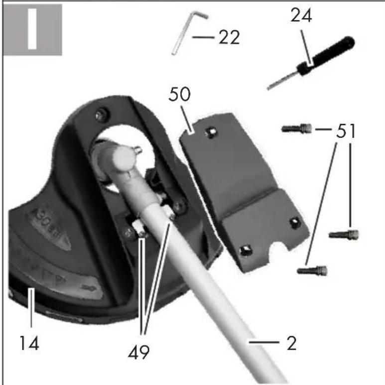
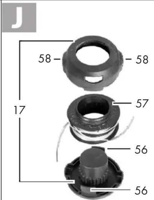
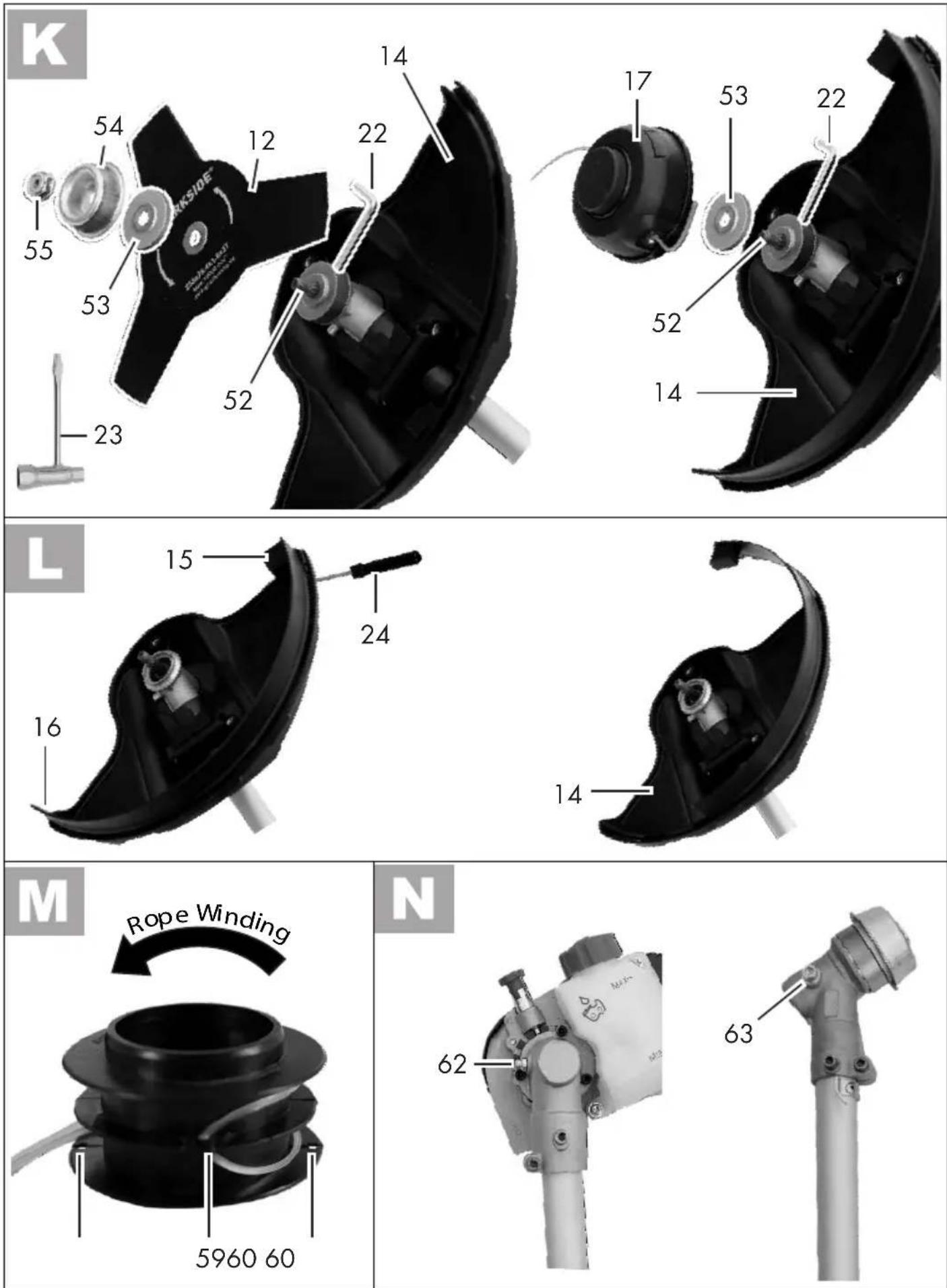
GRIZZLY TOOLS GMBH & CO. KG

IAN 385586_2107

8

