GDMF500R - Other computer accessories SONY - Free user manual and instructions
Find the device manual for free GDMF500R SONY in PDF.
| Product type | Trinitron FD 21-inch CRT monitor |
| Brand | Sony |
| Model | GDMF500R |
| Screen size | 21 inches (diagonal), display area 403.8 x 302.2 mm (19.8 inches) |
| Maximum resolution | 2048 x 1536 pixels |
| Recommended resolution | 1600 x 1200 pixels |
| Horizontal frequency | 30 to 121 kHz |
| Vertical frequency | 48 to 160 Hz |
| Grid pitch | 0.22 mm |
| Video input connectors | HD15 (VGA) and BNC (5 connectors: R, G, B, H, V) |
| USB connectors | 1 upstream, 4 downstream (USB 1.1) |
| Power supply voltage | 100-240 V AC, 50/60 Hz |
| Power consumption | Approximately 145 W (normal), ≤ 1 W in deep sleep |
| Dimensions (W x H x D) | 502 x 511 x 480.3 mm |
| Weight | Approximately 33 kg |
| Power saving functions | VESA DPMS, ENERGY STAR, NUTEK |
| OSD menu languages | French, English, German, Spanish, Italian, Dutch, Swedish, Russian, Japanese |
| Available adjustments | Brightness, contrast, size, centering, zoom, geometry, convergence, color (SIMPLE, EXPERT, sRGB), moiré, degaussing |
| Plug & Play compatibility | DDC (Display Data Channel) |
| Maintenance and cleaning | Soft cloth, mild detergent; do not use alcohol or benzene |
| Safety | Automatic degaussing at power-on; do not block ventilation openings |
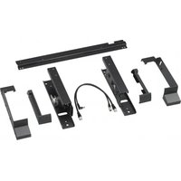
| Supplied accessories | Power cord, HD15 video signal cable, USB cable, G3 adapter, installation diskette, warranty card |
Frequently Asked Questions - GDMF500R SONY
User questions about GDMF500R SONY
0 question about this device. Answer the ones you know or ask your own.
Ask a new question about this device
Download the instructions for your Other computer accessories in PDF format for free! Find your manual GDMF500R - SONY and take your electronic device back in hand. On this page are published all the documents necessary for the use of your device. GDMF500R by SONY.
USER MANUAL GDMF500R SONY
Trinitron Color Graphic Display
Operating Instructions GB
Mode d'emploi FR
Bedienungsanleitung DE
Manual de instrucciones ES
Istruzioni per l'uso
Hctpyku no 3Kcnlyatau R
Bruksanvising
Gebruiksaanwijzing NL
GDM-F500R
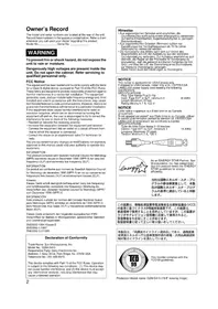
Owner's Record
The model and serial numbers are located at the rear of the unit. Record these numbers in the spaces provided below. Refer to them whenever you call upon your dealer regarding this product. Model No. __ Serial No. ____
WARNING
To prevent fire or shock hazard, do not expose the unit to rain or moisture.
Dangerously high voltages are present inside the unit. Do not open the cabinet. Refer servicing to qualified personnel only.
FCC Notice
This equipment has been tested and found to comply with the limits for a Class B digital device, pursuant to Part 15 of the FCC Rules. These limits are designed to provide reasonable protection against harmful interference in a residential installation. This equipment generates, uses, and can radiate radio frequency energy and, if not installed and used in accordance with the instructions, may cause harmful interference to radio communications. However, there is no guarantee that interference will not occur in a particular installation. If this equipment does cause harmful interference to radio or television reception, which can be determined by turning the equipment off and on, the user is encouraged to try to correct the interference by one or more of the following measures:
- Reorient or relocate the receiving antenna.
- Increase the separation between the equipment and receiver.
- Connect the equipment into an outlet on a circuit different from that to which the receiver is connected.
- Consult the dealer or an experienced radio/TV technician for help. You are cautioned that any changes or modifications not expressly approved in this manual could void your authority to operate this equipment.
EN 55022 Compliance (Czech Republic Only)
This device belongs to category B devices as described in EN 55022, unless it is specifically stated that it is a category A device on the specification label. The following applies to devices in category A of EN 55022 (radius of protection up to 30 meters). The user of the device is obliged to take all steps necessary to remove sources of interference to telecommunication or other devices.
This product complies with Swedish National Council for Metrology (MPR) standards issued in December 1990 (MPR II) for very low frequency (VLF) and extremely low frequency (ELF).
INFORMATION
This notice is applicable for USA/Canada only. If shipped to USA/Canada, install only a UL LISTED/CSA LABELLED power supply cord meeting the following specifications: SPECIFICATIONS Plug Type Nema-Plug 5-15p Cord Type SVT or SJT, minimum 3 18 AWG Length Maximum 15 feet Rating Minimum 7 A, 125 V
NOTICE
As an ENERGY STAR Partner, Sony Corporation has determined that this product meets the ENERGY STAR guidelines for energy efficiency.

This monitor complies with the TCO'99 guidelines.
Declaration of Conformity
Trade Name: Sony
Model No.: GDM-F500R
Responsible Party: Sony Electronics Inc.
Address: 1 Sony Drive, Park Ridge, NJ. 07656 USA Telephone No.: 201-930-6970
This device complies with Part 15 of the FCC Rules. Operation is subject to the following two conditions: (1) This device may not cause harmful interference, and (2) this device must accept any interference received, including interference that may cause undesired operation.
Table of Contents
Precautions 4
Identifying parts and controls 5
Setup. .6
Step 1: Connect your monitor to your computer 6
Step 2: Connect the power cord. 7
Step 3: Turn on the monitor and computer 7
Connecting Universal Serial Bus (USB) compliant peripherals . 8
Selecting the on-screen menu language (LANG). 8
Selecting the input signal 9
Automatically sizing and centering the picture (AUTO) 9
Customizing Your Monitor 10
Navigating the menu. 10
Adjusting the brightness and contrast. 11
Adjusting the size of the picture (SIZE) 11
Adjusting the centering of the picture (CENTER) 12
Enlarging or reducing the picture (ZOOM) 12
Adjusting the shape of the picture (GEOM) 12
Adjusting the convergence (CONV) 12
Adjusting the quality of the picture (SCREEN) 13
Adjusting the color of the picture (COLOR) 13
Additional settings (OPTION) 15
Resetting the adjustments 16
Technical Features 16
Preset and user modes. 16
Power saving function. 16
Troubleshooting. 17
If thin lines appear on your screen (damper wires). 17
On-screen messages 17
Trouble symptoms and remedies 18
Self-diagnosis function 20
Specifications. 20
Appendix.
- Preset mode timing table
TCO'99 Eco-document
Precautions
Warning on power connections
- Use the supplied power cord. If you use a different power cord, be sure that it is compatible with your local power supply.
For the customers in the UK
If you use the monitor in the UK, be sure to use the supplied UK power cable.
Example of plug types
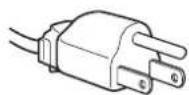
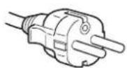
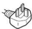
for 100 to 120 V AC for 200 to 240 V AC for 240 V AC only
- Before disconnecting the power cord, wait at least 30 seconds after turning off the power to allow the static electricity on the screen's surface to discharge.
After the power is turned on, the screen is demagnetized (degaussed) for about 3 seconds. This generates a strong magnetic field around the screen which may affect data stored on magnetic tapes and disks placed near the monitor. Be sure to keep magnetic recording equipment, tapes, and disks away from the monitor.
The equipment should be installed near an easily accessible outlet.
Installation
Do not install the monitor in the following places:
- on surfaces (rugs, blankets, etc.) or near materials (curtains, draperies, etc.) that may block the ventilation holes
- near heat sources such as radiators or air ducts, or in a place subject to direct sunlight
- in a place subject to severe temperature changes
- in a place subject to mechanical vibration or shock
- on an unstable surface
- near equipment which generates magnetism, such as a transformer or high voltage power lines
- near or on an electrically charged metal surface
Maintenance
- Clean the screen with a soft cloth. If you use a glass cleaning liquid, do not use any type of cleaner containing an anti-static solution or similar additive as this may scratch the screen's coating.
- Do not rub, touch, or tap the surface of the screen with sharp or abrasive items such as a ballpoint pen or screwdriver. This type of contact may result in a scratched picture tube.
- Clean the cabinet, panel and controls with a soft cloth lightly moistened with a mild detergent solution. Do not use any type of abrasive pad, scouring powder or solvent, such as alcohol or benzene.
Transportation
When you transport this monitor for repair or shipment, use the original carton and packing materials.
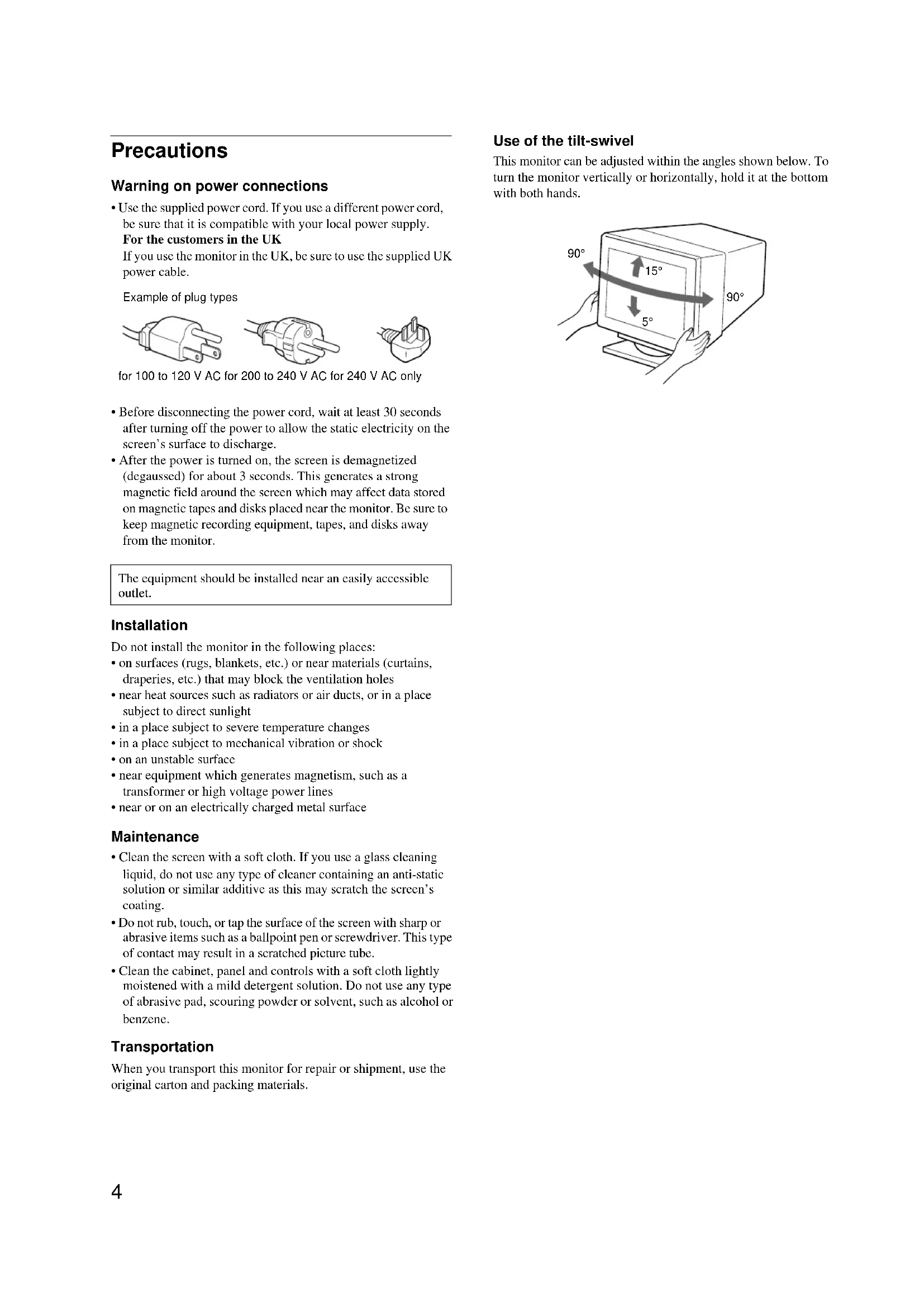
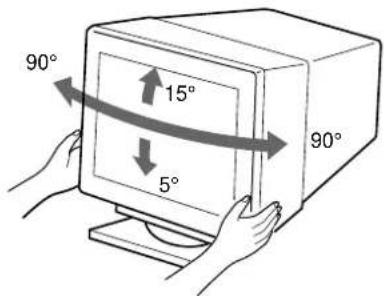
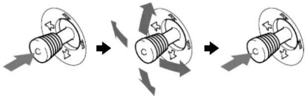
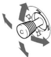
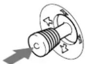
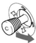
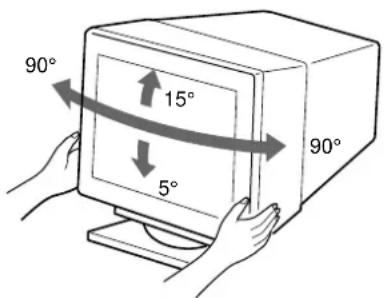
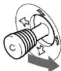
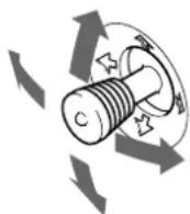
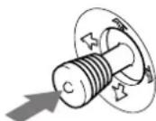
Use of the tilt-swivel
This monitor can be adjusted within the angles shown below. To turn the monitor vertically or horizontally, hold it at the bottom with both hands.
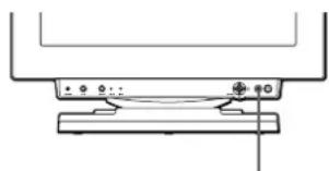
Identifying parts and controls
See the pages in parentheses for further details.
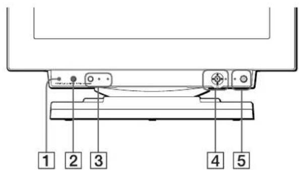
Front
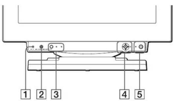
1RESET (reset) button (page 16)
This button resets the adjustments to the factory settings.
2ASC (auto sizing and centering) button (page 9)
This button automatically adjusts the size and centering of the picture.
3INPUT button and HD15 / BNC indicators (page 9)
This button selects the HD15 or BNC video input signal. Each time you press this button, the input signal and corresponding indicator alternate.
4Joystick (page 11)
The joystick is used to display the menu and make adjustments to the monitor, including brightness and contrast adjustments.
5 (power) switch and indicator (pages 7, 16, 20)
This button turns the monitor on and off. The power indicator lights up in green when the monitor is turned on, and either flashes in green and orange, or lights up in orange when the monitor is in power saving mode.
6AC IN connector (page 7)
This connector provides AC power to the monitor.
7USB (universal serial bus) upstream connector (page 8)
Use this connector to link the monitor to a USB compliant computer.
8USB (universal serial bus) downstream connectors (page 8)
Use these connectors to link USB peripheral devices to the monitor.
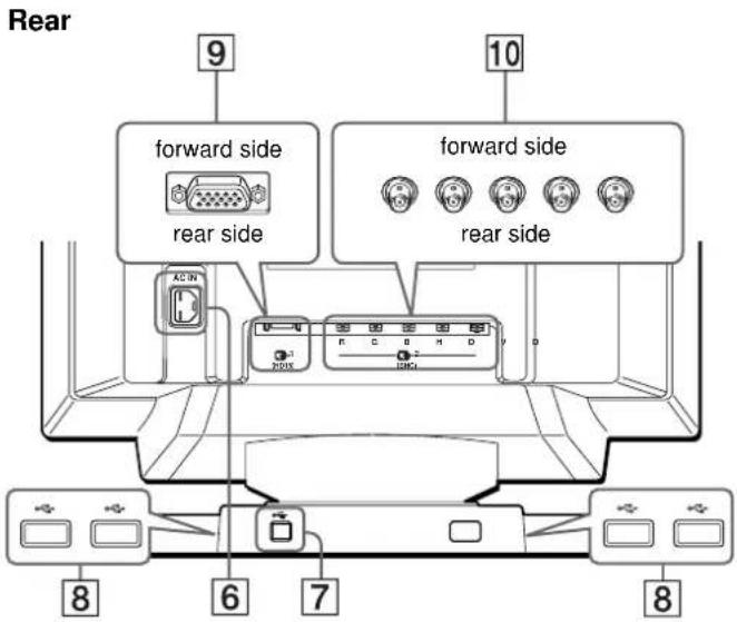
Video input 1 connector (HD15) (page 6)
This connector inputs RGB video signals (0.700 Vp-p, positive) and sync signals.
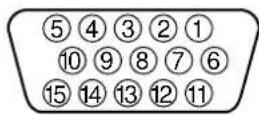
| Pin No. Signal | ||
| 1 | Red | |
| 2 Green (Composite Sync on Green) | ||
| 3 | B | l u e |
| 4 ID (Ground) | ||
| 5 DDC Ground* | ||
| 6 Red Ground | ||
| 7 Green Ground | ||
| 8 Blue Ground | ||
| 9 DDC + 5V* | ||
| 10 Ground | ||
| 11 ID (Ground) | ||
| 12 Bi-Directional Data (SDA)* | ||
| 13 H. Sync | ||
| 14 V. Sync | ||
| 15 Data Clock (SCL)* | ||
- DDC (Display Data Channel) is a standard of VESA.
Video input 2 connector (BNC) (page 6)
This connector inputs RGB video signals (0.700 Vp-p, positive) and sync signals.
Setup
Before using your monitor, check that the following accessories are included in your carton:
Power cord (1)
HD15 video signal cable (1)
- USB cable (1)
G3 adapter (for Macintosh blue and white system) (1)
- Setup Disk (1)
Warranty card (1)
Notes on cleaning the screen's surface (1)
This instruction manual (1)
Step 1:Connect your monitor to your computer
Turn off the monitor and computer before connecting.
Notes
- Do not touch the pins of the video signal cable connector as this might bend the pins.
- When connecting the video signal cable, check the alignment of the HD15 connector. Do not force the connector in the wrong way or the pins might bend.
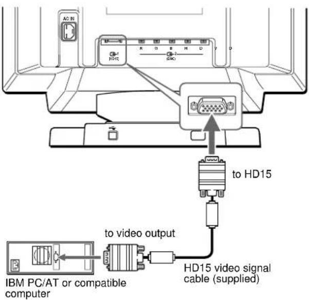
- Connecting to an IBM PC/AT or compatible computer
Connecting to a Macintosh computer
Use the supplied G3 adapter (for blue and white system).
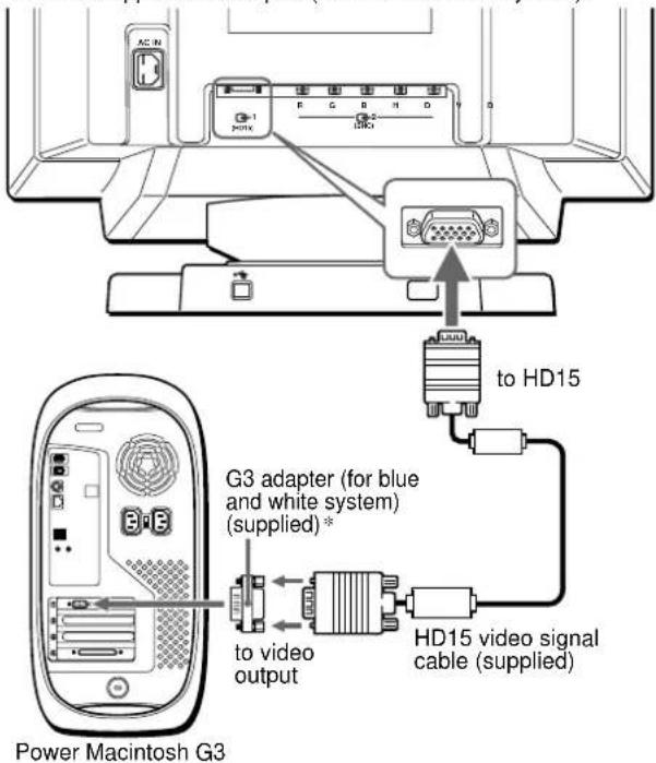
- Connect the supplied Macintosh adapter to the computer before connecting the cable. This adapter is compatible with the Power Macintosh G3 computer that has three rows of pins. If you are connecting to the other version of Power Macintosh G3 series computer with two rows of pins or other models, you will need a different adapter (sold separately).
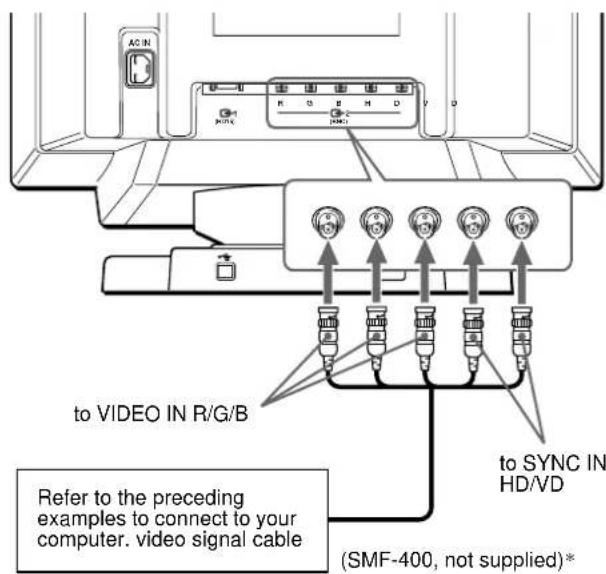
- Connecting to the five BNC connectors
- Connect the cables from left to right in the following order: Red-Green-Bluc-HD-VD.
Note
Plug & Play (DDC) does not apply to the five BNC connectors. If you want to use Plug & Play, connect your computer to the HD15 connector using the supplied video signal cable.
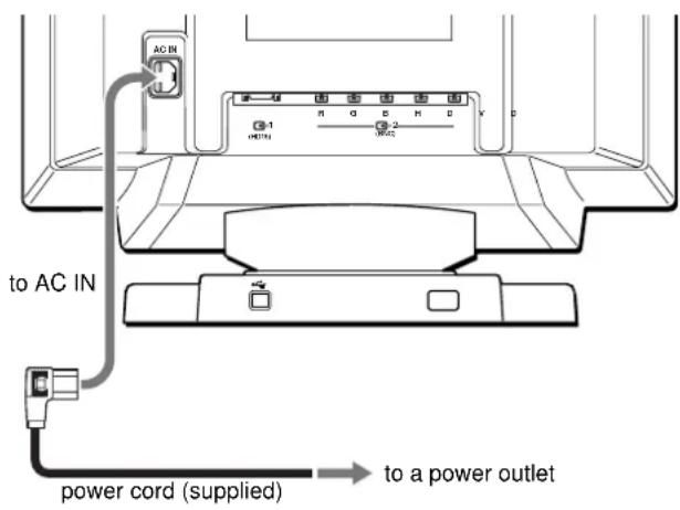
Step 2:Connect the power cord
With the monitor and computer switched off, first connect the power cord to the monitor, then connect it to a power outlet.
Step 3:Turn on the monitor and computer
First turn on the monitor, then turn on the computer.

The installation of your monitor is complete.
If necessary, use the monitor's controls to adjust the picture.
If no picture appears on your screen
- Check that the monitor is correctly connected to the computer.
- If NO INPUT SIGNAL appears on the screen, try changing the input signal (page 9), and confirm that your computer's graphic board is completely seated in the correct bus slot.
- If you are replacing an old monitor with this model and OUT OF SCAN RANGE appears on the screen, reconnect the old monitor. Then adjust the computer's graphic board so that the horizontal frequency is between 30 - 121kHz , and the vertical frequency is between 48 - 160Hz .
For more information about the on-screen messages, see "Trouble symptoms and remedies" on page 18.
Setup on various OS (Operating System)
This monitor complies with the "DDC" Plug & Play standard and automatically detects all the monitor's information with the Windows Plug & Play function. No specific driver needs to be installed to the computer. If you connect the monitor to your PC, and then boot your PC for the first time, the setup Wizard may be displayed on the screen. Click on "Next" several times according to the instructions from the Wizard until the Plug & Play Monitor is automatically selected so that you can use this monitor. If your PC/graphics board has difficulty communicating with this monitor, load the supplied Setup Disk. Refer to the "Read Me" file on the Disk about the procedure to install. You can also download the information by accessing the web site of the graphics board's manufacturer.
For customers using Windows NT4.0
Monitor setup in Windows NT4.0 does not use the display driver. Refer to the Windows NT4.0 instruction manual for further details on adjusting the resolution, refresh rate, and number of colors.
Connecting Universal Serial Bus (USB) compliant peripherals
Your monitor has one upstream and four downstream USB connectors. They provide a fast and easy way to connect USB compliant peripheral devices (such as keyboards, mice, printers and scanners) to your computer using a standardized USB cable. To use your monitor as a hub for your peripheral devices, connect the USBs as illustrated below.
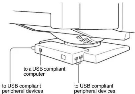
1 Turn on the monitor and computer.
2 Connect your computer to the square upstream connector using the supplied USB cable.
For customers using Windows
If a message appears on your screen, follow the on-screen instructions and select Generic USB Hub as the default setting.
3 Connect your USB compliant peripheral devices to the rectangular downstream -4GB connectors.
Notes
- Not all computers and/or operating systems support USB configurations. Check your computer's instruction manual to see if you can connect USB devices.
- In most cases, USB driver software needs to be installed on the host computer. Refer to the peripheral device's instruction manual for further details.
- The monitor functions as a USB hub as long as the monitor is either "on" or in power saving mode.
- If you connect a keyboard or mouse to the USB connectors and then boot your computer for the first time, the peripheral devices may not function. First connect the keyboard and mouse directly to the computer and set up the USB compliant devices. Then connect them to this monitor.
- Do not lean on the monitor when plugging in the USB cables. The monitor may suddenly shift and cause injury.
Selecting the on-screen menu language (LANG)
English, French, German, Spanish, Italian, Dutch, Swedish, Russian and Japanese versions of the on-screen menus are available. The default setting is English.
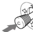
1 Press the joystick.
See page 11 for more information on using the joystick.

2 Move the joystick to highlight ANG and press the joystick again.
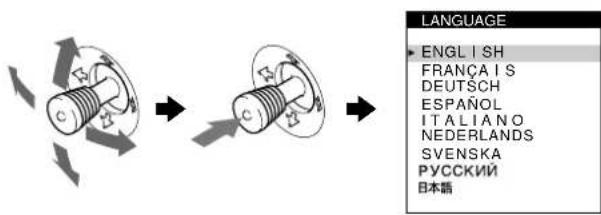
3 Move the joystick up or down to select a language and press the joystick again.
- ENGLISH
FRANCAIS: French - DEUTsCH: German
- ESPANOL: Spanish
ITALIANO:Italian
NEDERLANDS: Dutch - SVENSKA: Swedish
·RVSOKN
·:csc
To close the menu
Press the joystick once to return to the main menu, and twice to return to normal viewing. If no buttons are pressed, the menu closes automatically after about 30 seconds.
To reset to English
Press the RESET button while the LANGUAGE menu is displayed on the screen.
Selecting the input signal
You can connect two computers to this monitor using the HD15 and BNC connectors. To switch between the two computers, use the INPUT button.
Press the INPUT button.
Each time you press this button, the input signal and corresponding indicator alternate.
When the button is pressed, BNC is selected, when the button is unpressed, HD15 is selected.


HD15
BNC
The selected connector appears on the screen for a few seconds. "HD15" or "BNC" appears on the screen.
Note
If no signal is input to the selected connector, NO INPUT SIGNAL appears on the screen. After a few seconds, the monitor enters the power saving mode. If this happens, switch to the other connector.
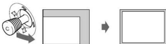
Automatically sizing and centering the picture (AUTO)
You can easily adjust the picture to fill the screen by pressing the ASC (auto sizing and centering) button, or by using the on-screen menu.
Using ASC button
Press the ASC button.
The picture automatically fills the screen.


Using the on-screen menu
1 Press the joystick to display the main MENU on the screen.
2 Move the joystick to highlight CENTER or SIZE and press the joystick again.
3 Move the joystick up or down to select AUTO).
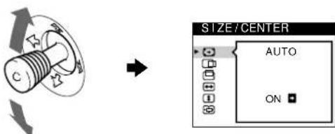
4 Move the joystick to the right
The picture automatically fills the screen.
Notes
- This function is intended for use with a computer running Windows or similar graphic user interface software that provides a full-screen picture. It may not work properly if the background color is dark or if the input picture does not fill the screen to the edges (such as an MS-DOS prompt).
Pictures with an aspect ratio of 5:4 (resolution: 1280 - 1024, 1800 - 1440) are displayed at their actual resolution and do not fill the screen to the edges.
The displayed image moves for a few seconds while this function is performed. This is not a malfunction.
Customizing Your Monitor
You can make numerous adjustments to your monitor using the on-screen menu.
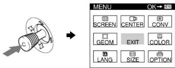
Navigating the menu
Press the joystick to display the main MENU on your screen. See page 11 for more information on using the joystick.
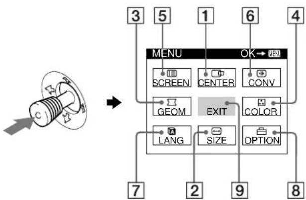
Use the joystick to select one of the following menus.
1CENTER (page 12)
Select the CENTER menu to adjust the picture's centering, size or zoom.
2SIZE (page 11)
Select the SIZE menu to adjust the picture's size, centering or zoom.
3GEOM (page 12)
Select the GEOM menu to adjust the picture's rotation and shape.
4COLOR (page 13)
Select the COLOR menu to adjust the picture's color temperature. You can use this to match the monitor's colors to a printed picture's colors.
5SCREEN (page 13)
Select the SCREEN menu to adjust the picture's quality. You can adjust the landing and moiré cancellation effect.
6CONV (page 12)
Select the CONV menu to adjust the picture's horizontal and vertical convergence.
7LANG (page 8)
Select the LANG menu to choose the on-screen menu's language.

8OPTION (page 15)
Select the OPTION menu to adjust the monitor's options. The options include:
- degaussing the screen
- changing the on-screen menu position
- locking the controls
9EXIT
Select EXIT to close the menu.
Displaying the current input signal
The horizontal and vertical frequencies of the current input signal are displayed in the main MENU. If the signal matches one of this monitor's factory preset modes, the resolution is also displayed.

Using the joystick
1 Display the main MENU and select the menu you want to adjust.
Press the joystick once to display the main MENU. Then move the joystick up, down, left, or right to highlight the desired menu. Press the joystick to select the menu item.
2 Adjust the menu.
Move the joystick up, down, left, or right to make the adjustment.
3 Close the menu.
Press the joystick once to return to the main menu, and twice to return to normal viewing. If no buttons are pressed, the menu closes automatically after about 30 seconds.
Resetting the adjustments
Press the RESET button. See page 16 for more information on resetting the adjustments.

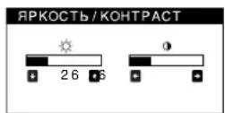
Adjusting the brightness and contrast
Brightness and contrast adjustments are made using a separate BRIGHTNESS/CONTRAST menu.
These settings are stored in memory for the signals from the currently selected input connector.
1 Move the joystick in any direction.
The BRIGHTNESS/CONTRAST menu appears on the screen.

2 Move the joystick up or down to adjust the brightness ( ) and left or right to adjust the contrast ( ).
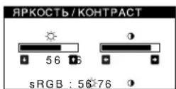
If you are using the sRGB mode
If you selected the sRGB mode in the COLOR menu, the following BRIGHTNESS/CONTRAST menu appears on the screen.
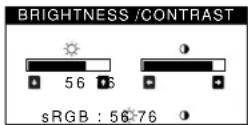
For more information about using the sRGB mode, see "Adjusting the color of the picture (COLOR)" on page 13.
The menu automatically disappears after about 3 seconds.
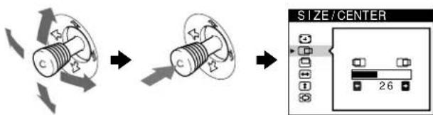
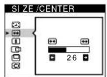
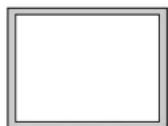
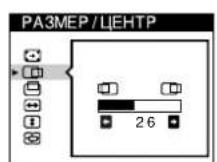
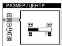
Adjusting the size of the picture (SIZE)
This setting is stored in memory for the current input signal.
1 Press the joystick.
The main MENU appears on the screen.
2 Move the joystick to highlight SIZE and press the joystick again.
The SIZE/CENTER menu appears on the screen.
3 First move the joystick up or down to select for horizontal adjustment, or for vertical adjustment. Then move the joystick left or right to adjust the size.
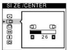
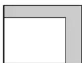
Adjusting the centering of the picture (CENTER)
This setting is stored in memory for the current input signal.
1 Press the joystick.
The main MENU appears on the screen.
2 Move the joystick to highlight CENTER and press the joystick again.
The SIZE/CENTER menu appears on the screen.
3 First move the joystick up or down to select for horizontal adjustment, or for vertical adjustment. Then move the joystick left or right to adjust the centering.
Enlarging or reducing the picture (ZOOM)
This setting is stored in memory for the current input signal.
1 Press the joystick.
The main MENU appears on the screen.
2 Move the joystick to highlight SIZE on CENTER and press the joystick ags
The SIZE/CENTER menu appears on the screen.
3 Move the joystick up or down to select zoom), and move the joystick left or right to enlarge or reduce the picture.
Note
Adjustment stops when either the horizontal or vertical size reaches its maximum or minimum value.
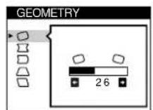
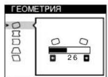
Adjusting the shape of the picture (GEOM)
The GEOM settings allow you to adjust the rotation and shape of the picture.
The (rotation) setting is stored in memory for all input signals.
All other settings are stored in memory for the current input signal.
1 Press the joystick.
The main MENU appears on the screen.
2 Move the joystick to highlight GEOM and press the joystick again.
The GEOMETRY menu appears on the screen.
3 First move the joystick up or down to select the desired adjustment item. Then move the joystick left or right to make the adjustment.
| Select To | |
| ○ | rotate the picture |
| ○ | expand or contract the picture sides |
| ○ | shift the picture sides to the left or right |
| ○ | adjust the picture width at the top of the screen |
| ○ | shift the picture to the left or right at the top of the screen |
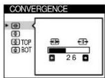
Adjusting the convergence (CONV)
The CONV settings allow you to adjust the quality of the picture by controlling the convergence. The convergence refers to the alignment of the red, green, and blue color signals.
If you see red or blue shadows around letters or lines, adjust the convergence.
These settings are stored in memory for all input signals.
1 Press the joystick.
The main MENU appears on the screen.
2 Move the joystick to highlight CONV and press the joystick again.
The CONVERGENCE menu appears on the screen.
3 First move the joystick up or down to select the desired adjustment item. Then move the joystick left or right to make the adjustment.
| Select To | |
| + | horizontally shift red or blue shadows |
| + | vertically shift red or blue shadows |
| +TOP | vertically shift red or blue shadows at the top of the screen |
| V CONVER TOP | |
| +BOT | vertically shift red or blue shadows at the bottom of the screen |
| V CONVER BOTTOM | |
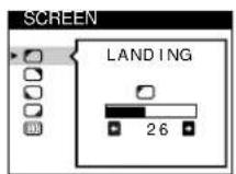
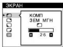
Adjusting the quality of the picture (SCREEN)
The SCREEN settings allow you to adjust the quality of the picture by controlling the moir and landing.
- If the color is irregular at the corners of the screen, adjust the landing.
- If elliptical or wavy patterns appear on the screen, cancel the moir.
The CANCEL MOIRE and MOIRE ADJUST settings are stored in memory for the current input signal. All other settings are stored in memory for all input signals.
1 Press the joystick.
The main MENU appears on the screen.
2 Move the joystick to highlight SCREEN and press the joystick again.
The SCREEN menu appears on the screen.
3 First move the joystick up or down to select the desired adjustment item. Then move the joystick left or right to make the adjustment.
| Select To | |
| LANDING | reduce any color irregularities in the screen's top left corner to a minimum. |
| LANDING | reduce any color irregularities in the screen's top right corner to a minimum. |
| LANDING | reduce any color irregularities in the screen's bottom left corner to a minimum. |
| LANDING | reduce any color irregularities in the screen's bottom right corner to a minimum. |
| CANCEL MOIRE* | turn the moire cancellation function ON or OFF. (MOIRE ADJUST) appears in the menu when you select ON. |
| MOIRE ADJUST | adjust the degree of moire cancellation until the moire is at a minimum. |
- Moire is a type of natural interference which produces soft, wavy lines on your screen. It may appear due to interference between the pattern of the picture on the screen and the phosphor pitch pattern of the monitor.
Example of moir
Note
The picture may become fuzzy when CANCEL MOIRE is set to ON.
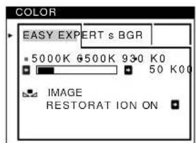
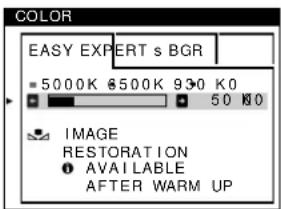
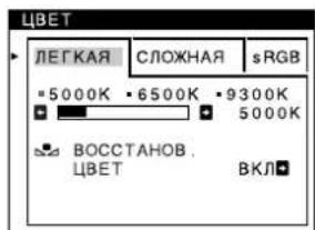
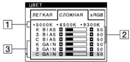
Adjusting the color of the picture (COLOR)
The COLOR settings allow you to adjust the picture's color temperature by changing the color level of the white color field. Colors appear reddish if the temperature is low, and bluish if the temperature is high. This adjustment is useful for matching the monitor's color to a printed picture's colors.
1 Press the joystick.
The main MENU appears on the screen.
2 Move the joystick to highlight COLOR and press the joystick again.
The COLOR menu appears on the screen.
3 Move the joystick left or right to select the adjustment mode.
There are three types of adjustment modes, EASY, EXPERT and sRGB.
4 First move the joystick up or down to select the desired adjustment item. Then move the joystick left or right to make the adjustment.
Adjust the selected mode according to the following instructions.
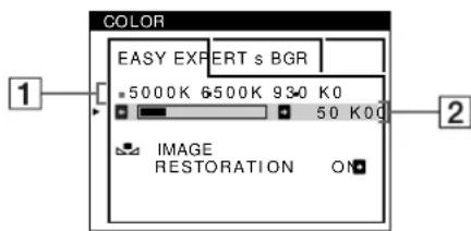
EASY mode
1 Move the joystick up or down to select the color temperature row 1. Then move the joystick left or right to select a color temperature.
The preset color temperatures are 5000K, 6500K, and 9300K. Since the default setting is 9300K, the whites will change from a bluish hue to a reddish hue as the temperature is lowered to 6500K and 5000K.
2 If necessary, fine tune the color temperature. Move the joystick up or down to select the color temperature row ②. Then move the joystick left or right to fine tune the color temperature.
If you fine tune the color temperature, the new color settings are stored in memory for each of the three color temperatures and item 1 of the on-screen menu changes as follows.
·[5000K]→[ ]
·[6500K]→[ ]
·[9300K]→[ ]
(continued)
EXPERT mode
You can make additional adjustments to the color in greater detail by selecting the EXPERT mode.
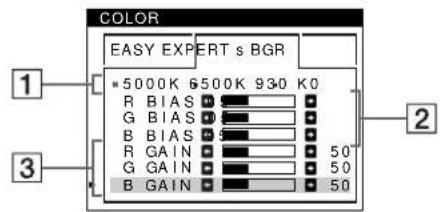
1 Move the joystick up or down to select the color temperature row 1. Then move the joystick left or right to select a color temperature.
2 Move the joystick up or down to select the adjustment item 2. Then move joystick left or right to adjust the BIAS (black level).
This adjusts the dark areas of an image.
3 Move the joystick up or down to select the adjustment item ③. Then move the joystick left or right to adjust the GAIN (white level).
This adjusts the light areas of an image.
You can adjust the R (red), G (green), B (blue) component of the input signal when making changes to items 2 and 3.
If you fine tune the color temperature, the new color settings are stored in memory for each of the three color temperatures and item 1 of the on-screen menu change as follows.
·[5000K]→[ ]
·[6500K]→[ ]
·[9300K]→[ ]
Setting the color temperature for each of the video input connectors
You can set the fine tuning of the color temperature in EASY or EXPERT mode for each of the video input connectors (HD15 and BNC).
1 Select the same adjustment mode and color temperature in the COLOR menu for both HD15 and BNC.
2 Fine tune the color temperature in each menu for HD15 and BNC.
The settings are stored in memory for each of the HD15 and BNC connectors.
For information on how to select the connector, see page 9.
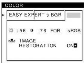
sRGB mode
The sRGB color setting is an industry standard color space protocol designed to correlate the displayed and printed colors of sRGB compliant computer products. To adjust the colors to the sRGB profile, simply select the sRGB mode in the COLOR menu. However, in order to display the sRGB colors correctly ( = 2.2 6500K) you must set your computer to the sRGB profile and adjust the brightness ( ) and contrast () to the numbers shown in the menu. For information on how to change the brightness ( ) and contrast () see page 11.
Note
Your computer and other connected products (such as a printer), must be sRGB compliant.
Restoring the color from the EASY or sRGB menus
The colors of most display monitors tend to gradually lose brilliance over several years of service. The IMAGE RESTORATION feature found in the EASY and sRGB menus allows you to restore the color to the original factory quality levels. The explanation below explains how to restore the monitor's color from the EASY menu.
1 Move the joystick left or right to select EASY or sRGB mode.
2 First move the joystick up or down to select (IMAGE RESTORATION). Then move the joystick to the right.
The picture disappears while the color is being restored (about 2 seconds). After the color is restored, the picture reappears on the screen again.
Notes
- Before using this feature, the monitor must be in normal operation mode (green power indicator on) for at least 30 minutes. If the monitor goes into power saving mode, you must return the monitor to normal operation mode and wait for 30 minutes for the monitor to be ready. You may need to adjust your computer's power saving settings to keep the monitor in normal operation mode for the full 30 minutes. If the monitor is not ready, the following message will appear.
- The monitor may gradually lose its ability to perform this function due to the natural aging of the picture tube.
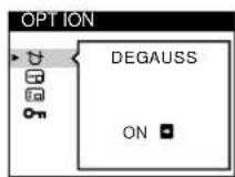
Additional settings (OPTION)
You can manually degauss (demagnetize) the monitor, change the menu position, and lock the controls.
1 Press the joystick.
The main MENU appears on the screen.
2 Move the joystick to highlight OPTION and press the joystick again.
The OPTION menu appears on the screen.
3 Move the joystick up or down to select the desired adjustment item.
Adjust the selected item according to the following instructions.
Degaussing the screen
The monitor is automatically demagnetized (degaussed) when the power is turned on.
To manually degauss the monitor, first move the joystick up or down to select DEGAUSS). Then move the joystick to the right.
The screen is degaussed for about 2 seconds. If a second degauss cycle is needed, allow a minimum interval of 20 minutes for the best result.
Changing the menu's position
Change the menu's position if it is blocking an image on the screen.
To change the menu's on-screen position, first move the joystick up or down to select (SDH POSITION) for horizontal adjustment, or (SDVPOSITION) for vertical adjustment. Then move the joystick left or right to shift the on-screen menu.
Locking the controls
To protect adjustment data by locking the controls, first move the joystick up or down to select CONTROL LOCK). Then move the joystick to the right, to select ON.
Only the (power) switch, EXIT, and CONTROL LOCK of the OPTION menu will operate. If any other items are selected, the oark appears on the screen.
To cancel the control lock
Repeat the procedure above and set CONTROL LOCK) to OFF.
Resetting the adjustments
This monitor has the following three reset methods. Use the RESET button to reset the adjustments.

Resetting a single adjustment item
Use the joystick to select the adjustment item you want to reset, and press the RESET button.
Resetting all of the adjustment data for the current input signal
Press the RESET button when no menu is displayed on the screen. Note that the following items are not reset by this method:
- on-screen menu language (page 8)
- adjustment mode in the COLOR menu (EASY, EXPERT, sRGB) (page 13)
- on-screen menu position (page 15)
control lock (page 15)
Resetting all of the adjustment data for all input signals
Press and hold the RESET button for more than two seconds.
Note
The RESET button does not function when ON (CONTROL LOCK) is set to ON.
Technical Features
Preset and user modes
When the monitor receives an input signal, it automatically matches the signal to one of the factory preset modes stored in the monitor's memory to provide a high quality picture at the center of the screen. (See Appendix for a list of the factory preset modes.) For input signals that do not match one of the factory preset modes, the digital Multiscan technology of this monitor ensures that a clear picture appears on the screen for any timing in the monitor's frequency range (horizontal: 30 - 121kHz , vertical: 48 - 160Hz ). If the picture is adjusted, the adjustment data is stored as a user mode and automatically recalled whenever the same input signal is received.
Note for Windows users
For Windows users, check your video board manual or the utility program which comes with your graphic board and select the highest available refresh rate to maximize monitor performance.
Power saving function
This monitor meets the power-saving guidelines set by VESA, ENERGY STAR, and NUTEK. If the monitor is connected to a computer or video graphics board that is DPMS (Display Power Management Signaling) compliant, the monitor will automatically reduce power consumption in three stages as shown below.
| Power mode Power consumption* | ( power) indicator | |
| normal operation | ≤ 145 W green | |
| 1 standby ≤ 15 W green and orange | alternate | |
| 2 suspend (sleep)** | ≤ 15 W green and orange | alternate |
| 3 active off*** (deep sleep)** | ≤ 1 W orange | |
| power off 0 W off | ||
- Figures reflect power consumption when no USB compatible peripherals are connected to the monitor.
"Sleep" and "deep sleep" are power saving modes defined by the Environmental Protection Agency.
* When your computer enters in a power saving mode, the input signal is cut and NO INPUT SIGNAL appears on the screen. After a few seconds, the monitor enters power saving mode.
Troubleshooting
Before contacting technical support, refer to this section.
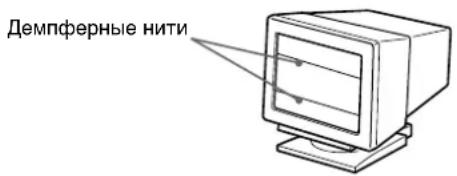
If thin lines appear on your screen (damper wires)
The lines you are experiencing on your screen are normal for the Trinitron monitor and are not a malfunction. These are shadows from the damper wires used to stabilize the aperture grille and are most noticeable when the screen's background is light (usually white). The aperture grille is the essential element that makes a Trinitron picture tube unique by allowing more light to reach the screen, resulting in a brighter, more detailed picture.

On-screen messages
If there is something wrong with the input signal, one of the following messages appears on the screen.
If NO INPUT SIGNAL appears on the screen
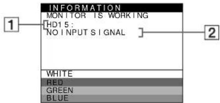
1The selected connector
This message shows the currently selected connector (HD15 or BNC).
2The input signal condition NO INPUT SINGAL
This indicates that no signal is input, or that no signal is input from the selected connector.
If OUT OF SCAN RANGE appears on the screen
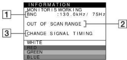
1The selected connector and the frequencies of the current input signal
This message shows the currently selected connector (HD15 or BNC). If the monitor recognizes the frequencies of the current input signal, the horizontal and vertical frequencies are also displayed.
The input signal condition OUT OF SCAN RANGE
This indicates that the input signal is not supported by the monitor's specifications.
3The remedies
CHANGE SIGNAL TIMING appears on the screen. If you are replacing an old monitor with this monitor, reconnect the old monitor. Then adjust the computer's graphic board so that the horizontal frequency is between 30 - 121 kHz, and the vertical frequency is between 48 - 160 Hz.
For more information, see "Trouble symptoms and remedies" on page 18.
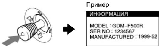
Displaying this monitor's name, serial number, and date of manufacture.
While the monitor is receiving a video signal, press and hold the joystick for more than three seconds to display this monitor's information box.
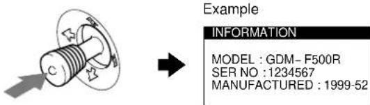
If the problem persists, call your authorized Sony dealer and give the following information.
- Model name: GDM-F500R
- Serial number
- Name and specifications of your computer and graphics board.
Trouble symptoms and remedies
If the problem is caused by the connected computer or other equipment, please refer to the connected equipment's instruction manual. Use the self-diagnosis function (page 20) if the following recommendations do not resolve the problem.
| Symptom Check these items | |
| No picture | |
| If the (1)(power) indicator is not lit | ·Check that the power cord is properly connected. ·Check that the (1)(power) switch is in the "on" position. |
| If the NO INPUT SIGNAL message appears on the screen, or if the (1)(power) indicator is either orange or alternating between green and orange | ·Check that the video signal cable is properly connected and all plugs are firmly seated in their sockets. If you are using the five BNC connectors, connect them in the correct order (from left to right: Red-Green-Blue-HD-VD) (page 6). ·Check that the INPUT switch setting is correct (page 9). ·Check that the HD15 video input connector's pins are not bent or pushed in. ■Problems caused by the connected computer or other equipment ·The computer is in power saving mode. Try pressing any key on the computer keyboard. ·Check that the computer's power is "on." ·Check that the graphic board is completely seated in the proper bus slot. |
| If the OUT OF SCAN RANGE message appears on the screen | ■Problems caused by the connected computer or other equipment ·Check that the video frequency range is within that specified for the monitor. If you replaced an old monitor with this monitor, reconnect the old monitor and adjust the frequency range to the following. Horizontal: 30 - 121 kHz Vertical: 48 - 160 Hz |
| If no message is displayed and the (1)(power) indicator is green or flashing orange | ·Use the Self-diagnosis function (page 20). |
| If using Windows 95/98 · If you replaced an old monitor with this monitor, reconnect the old monitor and do the following. Install the supplied Setup Disk (page 7) and select this monitor ("GDM-F500R") from among the Sony monitors in the Windows 95/98 monitor selection screen. If you choose to select "Plug and Play," connect the monitor to the computer with the HD15 video signal cable. You cannot use the five BNC connectors. | |
| If using a Macintosh system · When connecting to a Power Macintosh G3 series computer that has three rows of pins, check that the supplied G3 adapter and the video signal cable are properly connected (page 6). ·For Power Macintosh G3 or other models which have two rows of pins, you will need a different adapter which is sold separately. | |
| Picture flickers, bounces, oscillates, or is scrambled | ·Isolate and eliminate any potential sources of electric or magnetic fields such as other monitors, laser printers, electric fans, fluorescent lighting, or televisions. ·Move the monitor away from power lines or place a magnetic shield near the monitor. ·Try plugging the monitor into a different AC outlet, preferably on a different circuit. ·Try turning the monitor 90° to the left or right. ■Problems caused by the connected computer or other equipment ·Check your graphics board manual for the proper monitor setting. ·Confirm that the graphics mode (VESA, Macintosh 21" Color, etc.) and the frequency of the input signal are supported by this monitor (Appendix). Even if the frequency is within the proper range, some video boards may have a sync pulse that is too narrow for the monitor to sync correctly. ·Adjust the computer's refresh rate (vertical frequency) to obtain the best possible picture. |
| Picture is fuzzy | ·Adjust the brightness and contrast (page 11). ·Degauss the monitor* (page 15). ·If CANCEL MOIRE is ON, the picture may become fuzzy. Decrease the moiré cancellation effect or set CANCEL MOIRE to OFF (page 13). |
| Picture is ghosting | ·Eliminate the use of video cable extensions and/or video switch boxes. ·Check that all plugs are firmly seated in their sockets. |
| Picture is not centered or sized properly | ·Perform the AUTO function (page 9). ·Adjust the size (page 11) or centering (page 12). Note that some video modes do not fill the screen to the edges. |
| Edges of the image are curved · Adjust the geometry (page 12). | |
| Wavy or elliptical pattern (moire) is visible | ·Set CANCEL MOIRE to ON and adjust the degree of moire cancellation until the moire is at a minimum (page 13). ■Problems caused by the connected computer or other equipment ·Change your desktop pattern. |
| Color is not uniform | ·Degauss the monitor* (page 15). If you place equipment that generates a magnetic field, such as a speaker, near the monitor, or if you change the direction the monitor faces, color may lose uniformity. ·Adjust the landing (page 13). |
| White does not look white | ·Adjust the color temperature (page 13). ·Check that the five BNC connectors are connected in the correct order (from left to right: Red-Green-Blue-HD-VD) (page 6). |
| Letters and lines show red or blue shadows at the edges | ·Adjust the convergence (page 12). |
| Monitor buttons do not operate (○pears on the screen) | ·If the control lock is set to ON, set it to OFF (page 15). |
| IMAGE RESTORATION function does not operate | ·Before using this function, the monitor must be in normal operation mode (green power indicator on) for at least 30 minutes. For more information on using the IMAGE RESTORATION function, see page 15. ·Adjust the computer's power saving settings to keep the monitor in normal operation mode for more than 30 minutes. ·The monitor may gradually lose its ability to perform this function due to the natural aging of the picture tube. |
| USB peripherals do not function | ·Check that the appropriate USB connectors are securely connected (page 8). ·Check that the (○) (power) switch is in the “on” position. ■Problems caused by the connected computer or other equipment ·Check that the power of any self-powered USB compliant peripheral devices is “on.” ·Install the latest version of the device driver on your computer. Contact your device's manufacturer for information about the appropriate device driver. ·If your USB compliant keyboard or mouse does not function, connect them directly to your computer, reboot your computer, and make any necessary adjustments to the USB settings. Then reconnect the keyboard or mouse to the monitor. ·For customers using Windows 95 1. Right-click on My Computer and select Properties. 2. Click on the Device Manager tab. Scroll down and select Universal Serial Bus Controller. →If Universal Serial Bus Controller does not appear, you need to load a USB supplement disk. Contact your computer's manufacturer for more information about obtaining a USB supplement disk. 3. Select Generic USB Device from the USB controller list and click on Properties. 4. If there is a check in the box next to “Disable in this hardware profile,” remove the check. 5. Click on Refresh. |
| A hum is heard right after the power is turned on | ·This is the sound of the auto-degauss cycle. When the power is turned on, the monitor is automatically degaussed for three seconds. |
- If a second degauss cycle is needed, allow a minimum interval of 20 minutes for the best result. A humming noise may be heard, but this is not a malfunction.
Self-diagnosis function
This monitor is equipped with a self-diagnosis function. If there is a problem with your monitor or computer(s), the screen will go blank and the (power) indicator will either light up green or flash orange. If the (power) indicator is lit in orange, the computer is in power saving mode. Try pressing any key on the keyboard.
(power) indicator
If the (power) indicator is green
1 Remove any plugs from the video input 1 and 2 connectors, or turn off the connected computer(s).
2 Press the (power) button twice to turn the monitor off and then on.
3 Move the joystick to the right for 2 seconds before the monitor enters power saving mode.
If all four color bars appear (white, red, green, blue), the monitor is working properly. Reconnect the video input cables and check the condition of your computer(s).
If the color bars do not appear, there is a potential monitor failure. Inform your authorized Sony dealer of the monitor's condition.
If the (power) indicator is flashing orange
Press the (power) button twice to turn the monitor off and then on.
If the () (power) indicator lights up green, the monitor is working properly.
If the (power) indicator is still flashing, there is a potential monitor failure. Count the number of seconds between orange flashes of the (power) indicator and inform your authorized Sony dealer of the monitor's condition. Be sure to note the model name and serial number of your monitor. Also note the make and model of your computer and video board.
Specifications
CRT 0.22mm aperture grille pitch
21 inches measured diagonally
90-degree deflection
FD Trinitron
Viewable image size Approx. 403.8· 302.2mm (w/h)
(16·12 inches)
19.8" viewing image
Resolution
Maximum Horizontal: 2048 dots
Vertical: 1536 lines
Recommended Horizontal: 1600 dots
Vertical: 1200 lines
Standard image area Approx. 388· 291mm (w/h)
(15^3 / 8· 11^1 / 2 inches)
or
Approx. 364· 291mm (w/h)
(14^3 / 8· 11^1 / 2 inches)
Deflection frequency* Horizontal: 30 to 121kHz
Vertical: 48 to 160Hz
AC input voltage/current 100 to 240V 50 - 60Hz 2.0 - 1.0A
Power consumption Approx. 145 W (with no USB devices connected)
Operating temperature 10^ to 40^
Dimensions Approx.502-511·480.3 mm (w/h/d) (19^7 / 8· 20^1 / 8· 19^1 / 4 inches)
Mass Approx. 33kg (72 lb 12 oz)
Plug and Play DDC1/DDC2B/DDC2Bi, GTF**
Supplied accessories See page 6
- Recommended horizontal and vertical timing condition
Horizontal sync width duty should be more than 4.8% of total horizontal time or 0.8~ s whichever is larger.
Horizontal blanking width should be more than 2.3 sec
Vertical blanking width should be more than 450~ sec
** If the input signal is Generalized Timing Formula (GTF) compliant, the GTF feature of the monitor will automatically provide an optimal image for the screen.
Design and specifications are subject to change without notice.
Table des Matieres
Précautions 4
MANUFACTURED:1999-52
Plug & Play DDC1/DDC2B/DDC2Bi, GTF**
MANUFACTURED:1999-52
Plug and Play DDC1/DDC2B/DDC2Bi, GTF**
Characteristica Plug and play
DDC1/DDC2B/DDC2Bi, GTF**
Verticalc: 1536 line
Verticalc: 1200 line
Plug & Play DDC1/DDC2B/DDC2Bi, GTF**
He yctaHaBnBaIe MOHToP B CJeDyIOxMecTaX:
- Ha MárKnX NOBepxHOCrX (KOBPnK, OeJAnu T.D.) NIN B6n3n OT dpynx MaTePnaNoB (3aHaBeCKn, WToPbI N T.I.), KOTOpblc MOryT npErpaNtB DoCTyN BO3dYxa K BEHTNJRAUHOHBIM OTBepCTnAM
B6n3O NTcOHTHKnOB TeNla, TaKnx KaK BaTapeu nn BO3dyXoBObI, a TaKxE B MeCTax, rDe BO3MOxHO IOnaDaHHe pRmORO COJIHeHOrO CBeTa - rnde H6JIIOJADIOTcpe3Kne KOle6aHnTeMtnepaTpybI
- rIe npCytCTByeT Bn6paun nn pe3Kne MexaHnueckne BO3dEICTBn
Ha HeyctOuYHBbIX NOBepxHOCTAX
PDAOM C NCTOCHNKAIM MArHnTHbIX NOJIe, TaKIMN KaTpaHCΦopMaTOpbl INB BICOKOBONbTHbe KaBeIN
PdOM HnHa MeTaJIInueckoIOBepxHocTnC HaINuHem 3JeKtpnuEeCKOTo 3apra
yxo
-ПротраиTe 3кран Мягков Ткань. Пп ИСПОЛБЗOBAHИ XIMNUECKNX CpeДТВ ДЯЧСКИ CTeKЛА He npIMeHЯTe JxIDKOcTn, coDEpЖaUne aHTNCTaTNUeCKNe IIN aHaJIOruHbIe Do6aBKN, Ta KAK OHI MOryT NOBpeDNTb NOKpbITHe 3KpaHa.
He cIeNyET npKacatbca K IncnIeIO, cKpeCTu nn CTyHaTb IO Hemy OCTpbIMN NII WepuaBbIMN PpeDMetamn (WapNKOBo pyKo, OTBeptKo). 3To MoKet npBecTN K NOBHeHIO LapaINH Na NobepxHOCTN 3JeKTPoHNO-JyHeBO Tpy6Kn.
- IpoTnpaTe KOpNc, DnCnnei n NaHeJIb ynpaBHeHHn MmKoTKaHbIO, CJIeRka CMOueHHo B Cna6om pactBope MOUeO cpeCTBa. He NOIb3yIeTceb rpy6bIMN TepkAmn, a6pa3nHBbIMn nactAMn nn TaKIMn pactBopNTenMn, KaK CnIpt Nnn 6eHNH.
TpaHcnpToPbOKa
Pn npeB03Ke MOHTopa nn erO doCTaBKe B peMOHTyIO MaTePCKyIO NOb3yIteCb 3aBOckoJ KapTOHHOKOPO6Koi yNAKOBOUHbIMMaTePnaJaAM.
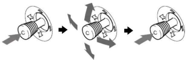
NcnoJIb3OBAHHe WapHnHpHOn Onpblc N3MeHReMbIM yIOM HaKJIOHa
MOHITOP MOXHO yCTaHaBnBaTa B yDIO6Hoe NOIOXKeHne,
N3MeHRe yTbHaKNoHa, KaK NOKa3aHo Ha pNCyHKe HIXe.
IOBopaHBAI np6Op No BEptNKaJI INI rOpN3OHTaJI,
dEpxTe erO 3a HxKHOIO YAcTb OBeIMn pyKaMn.
IdeHTnФнkauzna DeTaJeN OpraHOB ynpabJIeHn
CM. cTpaHnUbI B CkO6kax dna IOnyHeHn IOnpO6hIX CBeJeHn.
PepednnaHEnb
1 Khonka RESET (c6poc) (ctp. 16)
Bo3BpaaaetnapaMeTpblKNCXoDhblIM3HaueHnM, yCTaHOBJIeHHblMa 3aBODe.
2 KhoNka ASC (aBtOMaTHueckn pa3Mep n ceHTpoBka) (CTp. 9)
A B T O M A T U N E C K N I O D C T P A N B A E T P a 3 M e p N U E H T P O B K Y N 3 0 6 p a x k e n i.
3 KhoIka INPUT (BXoI) n HnIkaTopbI HD15/BNC (ctp.9)
Bb6npaet BxOAnHOBuJeocnHaI HD15 nnn BNC.
Pn KaKdom HaxaTm KHOKN 3MeHReTc TIN BXoHOrO CnHaJa N NOKa3aHr COOTBeTCTByIOUeRo INdkaTopa.
4ДжоICTNK(cTp.11)
KoCTNK NcNoJIb3yETcIg OTo6paKeHn MeHIO BbINOJIHeHHN HAcTpoE KMOHTOpA, BKIOUHa peryNPOBky RPKOCTu KOHTpactHOCTN.
5 BbIKNoHcyTeIb HnHdNkAtOp (nHTaHne) (cTp.7,16,20)
3Ta KhoNkA BKNIOHae T N BBIKIOHaeT MOHITOp.
KordaMOHITOP BKNIOUeH, INHINKaTOp rOpNT 3eJIeHBIM, a KOrda MOHITOP B pEXNME 3KOHOMN 3Heprn, OH rOpNT NNI MIRaET 3eJIeHBIM I OpaHKeBBIM, NII npocTo opaHKeBBIM.
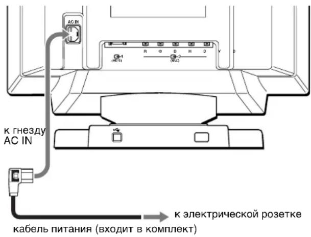
6 THe3do AC IN (cTp.7)
Ipaet 3neKtpueeckoe nHTaHHe Ha MOHTOp.
7 BxOHOH pa3bEM USB (yHnBepcaJIbHa nocneIOBaTeJIbHa (tP.8)
Vcnonb3yIte 3OT pa3bEm IIN NOKIOUeHnK KOMnbIoTepy,NOdEpxNBAIOUeMy cTahapr USB.
8 BbIXOHbIe pa3beMbI USB (yHnBepcaIbHa nocJeIOBaTeIbHa 1nHa) (cTp.8)
NcnoB3yIte 3Tu pa3bEmbln noKIOUeHnK MOHTOpny nepupepnHbIX yCTpoiCTB, nOdePknBaIOx cTAnapt USB.
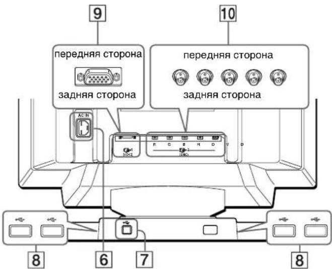
3aHnnaheB
9 THe3Do BnDeoBxoJa 1 (HD15) (CTp.6)
IpaetBndeocnHaNBi RGB (0,700 Vp-p, noJoxnt.) n CnHaNb ciHxpoHn3aun.
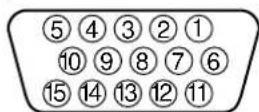
KoHTAKT No. CnHAn
1 Kpacnb
2 3eJIeHbI (KOM6HHNPOBaHHaCINHXPOH3aUHn no 3eJIeHOMy)
3 CnHn
4ID(3a3emneHne)
5 3a3eMJIHeH DDC
63a3eMJIeHneKpaCHoro
73a3emnne 3eHoro
83a3eMHeHne CnHero
9 DDC+5B*
103a3emnene
11 ID (3a3eMneHne)
12 KaHAn DByCTOpOHero O6MeHa DaHHbIX (SDA)*
13 TOpn3oHTaBHaCnHxPOH3aU
14 BepTnKaIbHa cHxpoH3aua
15 XpoHOMeTpax daHHbix (SCL)
10 The3do BndeoeBxoja 2 (BNC) (ctp.6)
IpaetBndeocnHaNBi RGB (0,700 Vp-p,pnoKnt.) n CnHaNb ciHxpoHn3aun.
Побrotовka к paбote
IpeepncnoJb3OBAHmEM MOHITopa npOBepbTe HAnuHne B Kopo6Ke cNeDyUoNX npHaNdxKHOCTe:
Ka6eIb nTuHaHn(1)
Ka6eBbVnDeocnHana HD15(1)
- Ka6eIb USB (1)
-Перекховн G3
He BKIIOUa MOHToP IN KOMNbIOTep, NOKJIIOHTe CHaUa KaBeJIb NITaHnR K MOHToPty, 3aTeM BKNIOHTe eroBpo3eTKy 3NEKTPoNTaHnR.
Uar 3: BkIIOuHTe MOHITOp N KOMNbIOTep
Chayajia BKJIOHHTe MOHITOP, 3aTeM BKJIIOHHTe KOMJIOTep.

YcTahOBka MOHITopa 3aBepueha.
B cnyuae Heo6xoDnMoocTn NOnb3yntecb opraHAMn ynpaBHeHr MOHTopAp nHaCTpOuKn N3o6paKHeHr.
Ecnn n3o6paxeHne He noBJIaETcHa 3KpaHe
- PpOBeBpTe npaBnIbHOCTb NOkNIOueHn MOHITOPa KOMMbIOtepy.
- Ecnn Ha 3kpane noBnreTc coo6eHne HET BXOHOFO CnHJAA, nonpo6ynte n3MeHnTB BXoHoi cInHaI (Ctp.9) n y6eHnTeCb, YTO rpaHnuecka nnata KOMNbOTepa HaJeKHO 3akpeHnHeBA COOTBeTCTByIOUem IHe3De WnHbl.
- Ecni daHHa MoeIb yCTaHaBnBaETCB BMeCTO CTaporo MOHITOPa, H a 3KpaHe NOBnRETCa COo6ueHne HEIONYCTUMbI I PFAPHUeCKNI PEKIM, BepHnTe npexHN MOHTOp Ha MeCTo. 3aTe M HacTpoTe rpaHnueckyIO pNaTy, Ta YTObI YAcTota Ropu3OHtAlbHO pa3BepTK 6bIa B Dnana3OHe 30 - 121 KΓu, a ChactoTa BEpTKaJIbHO pa3BepTKN - B Dnana3OHe 48 - 160 Γu.
DOnOHInTeIbHbIe CBeHeHHaO6 3KpaHbIX COoBSeHHaX cm.B pa3dene "CmNTombl HeNoJaOK n DeiCTBnA NO IN yCTpaHeHHo" Ha cTp.18.
YcTaHOBkaHa pa3IuHbIXOC (onepaunOHbIX cncTeMax)
JaHHb MOHnTOP OTBeuHaT Tpe6oBaHNr CtAHapTa "DDC" Plug & Play n ABOtOMaTHueCKn O6hApYxHBaET BcO INHpopMaUNo MOHnTOpe c NOMOsbO cyHKunn Plug & Play B CnCTeMe Windows. Heo63aTeBHo yCTaHbJIbBaT ha KOMNbItepe KaKne-JIn6o cneUmaIbHbIe dpaINBepbI.
EcIn BbI NOcOeINHReTe 3OT MOHtOp K NIK N BnepBbIe
3aRpyKaTe KOMNbIOTep,Ha 3KpaHe MoXeT 6bITb OTo6paxeHo
DIIANOBOE OKHO nporpaMMbYCTaHOBKN.HeCKoNBKO pa3
HaxMNTe KHONky "Next" B COOTBeTCTBm C yKa3aHNMa
nporpaMMb YCTaHOBKn, Noka He 6yDeT aBTOMaTHueckn Bbl6paH
MOHtOp Plug & Play, YTO6bI 3OT MOHtOp MOXHO 6bl0
NCNoB3OBaBt.
Ecnn KOMnIbTeP, rpaHnecka KapTa He Moryr npabInbHo yCTaHOBt b KOHTAKT C MOHITOpOM, 3arpy3nte npnnaRaembl yCTaHOBOHyb dNCK. YTO6bl O3HaKoMnTBc c npOeDpyoyn yCTaHOBKn, CM. Ha DNcke paJn "Read Me". DOnonHnTeNbHbIe CBedeHn MoXHO TaKHe nOlyuHb Ha Web-y3Ne n3roToBnTeNa rpaHnecko KaPTbl.
4To6bl3aKpbItb MeHIO
HaxMNTe JKOCTNK OIN pa3, YTO6bI BepHyTbC B rJNaBHOE MEHIO, IN DBa pa3a -ДЛ NBO3BpATA B HopMaJIbHbI pEXIM npOCMOTpa. Ecn KONKHe 6bln HaxaTbI, To 3KpaHHoe MeHIO ABTomATueckn Ncye3aET npN6n3ntEnbHo Yepe3 30 cekyHd.
ДЯВОЗБРATAKaHrJINCKOMYH3bIKY
HaxmTe KhoNky RESET, noka MeHo LANGUAGE BbIbeNo Ha 3KpaH.
BbI6Op BXoHoro cnHaJa
K DaHHOMy MoHToPy MoXHo NOJKnIIOHTb Dba KOMNbIoTepa, NcNoJIb3yra pa3bEmbl HD15 n BNC.
YTo6bI nepeKIOuHTbcra C OJHOrO KOMNbIOTepa Ha npyro, nCnoJIb3yIte KhoNky INPUT.
Haxmnte KhONky INPUT.
PnKaJdOM HaaKATN KHOKNI N3MeHReTc TIN BXOHNOrCnHaHa NOKa3aHn COOTBETCTByIOUeI OHNkAToPA.
Пин hashaToH KhONKe BbIbpaH cnrHaN BNC,пр otXaToH -cnrHaN HD15.


HD15

BNC
Bb6paHoe rHe3do noRbIReTcHa 3KpaHe Ha HeckoJIbKO cekyHd.
Ha 3kpaHne nOBuTcH "HD15" uNn "BNC"
PpmeuHne
Ecnn CnHaHne noaetc HbBbpaHHb pa3bEm, Ha 3Kpae NoBnTc coo6eHHe HET BXOHO CnHA. Ype3 HeckoBko Cekynd MOHTOP nepexoNT B pexIM 3heproScbepeJHn. Ecnn 3TO npocxOHT, nepeKnIOHTe Ha dpyro na3bem.
ABTOMaTnuecka NODcTpOiKa pa3Mepa N cEHTPOBKn n3o6paXeHnA (ABTOΦOPMAT)
Pa3mep n ceHTpOBka n3o6paXeHn ABToMaTHueCKn NOCTpanBaKOTc H a 3kpaHe NyTeM HaxKaTn KHOKN ASC (aBTopa3mep n ceHTpOBka), nIbO npn NMOoun 3KpaHHOro MeHIO.
IcnoJb3OBAHne KhoNk ASC
HaKMTe KONKy ASC.
I3o6paXeHne aBTOMaTnueckn noDCtpanBaetcno 3KpaHy.


IcnoJb3ObaHne 3KpaHHoro MeHIO
1 Haxmte JxOoiTnK dIa OTo6paXeHnHa 3KpaHe rnaBHoro MeHIO (MENU).

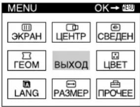
2 Nepemecnte JKOcTNK, TTO6bl BbIDeJIITb 3JemeHT DEHTP, nN PAA3MEP u HaxMMte JKOcTnK eue pa3.

3 NepemaaTe JxOyCTNK BBepx NIN BHN3,HTo6bI BBi6paTb (ABTOΦOPMAT).
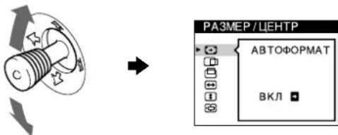
4IepemecnteJxKoNcTKBnpaBO
I3o6paXeHHe aBToMaTuYeCKn POnCTpaNBAeTcN oKpaHy.

PpmeaHn
- 3TaФункципгдза3нчсета Дд ИСПОьЗоВИСКOMПБТЕРOM, paobotAOUIM NOД Windows IINI pOrpamMHBIM OeCnepeHEM C NOIO6HbIM rPcAChEckm INHTepFeiCOM, KOTOpbIДaET NOIHO3KpaHnOHe O3O6paxKeHNe. OHa MoKET cPa6aTbIBaTb HnPaBnIbHo, ecN NBy6pHa TEmHaФOHOBaJ CBETOBaR nAnITpa INI ECN BxOdHoi CMrHJI He 3aONJIeT EkpanДо КрaEB (HaprimEp, KOMaHdHЯ CTpoka MS-DOS).
ИЗБРАСЕНСФОМТВIM COOTHOWEHNEM 5:4 (pa3peSHEHNE:1280.1024,1800.1440) OTO6PaxaIOTc CO CBOIM PaKTHueCKM pa3peSHEHEM He 3anONHJIOT 3KpAH Do KpaEB.
-Пи Вынгелпим 3ToIОпалIMВ TeЧЕп HeckoькИx CekyHd MOKET npoICXODHTb CMEUeHne N3O6paKeHn. 3TO He RaBJIeTcH HENONaIKoN.
Повстpoиka монитopa
BolbwaHacTpoek MOHTopa npo3BOUNTCa NOMOJIbIO 3KpaHHOro MeHIO.
BbIOHT Ha dncnne MeHIO UEHTP nIa noCTpoKu ceHTPOBKn, pa3Mepa, yMehbweHn yBeneHn n3o6paKeHn.
2 PA3MEP (ctp. 11)
BbOuHT Ha nCnne MeHIO PA3MEP IaI noCTpOKn pa3Mepa, ceHTPOBKn, yMeHbWeHn yBeNueHn n3o6paXeHN.
3 T EOM (cTp. 12)
BbOHT Ha nCnne MeHIO
FEOM dIa NoCTpoKu
noBopota n φopMbI paCTpa.
4 LBT (ctp. 13)
BbIOuNT Ha DCnne
MeHIO UBE TnA
NOCTPOKIN CBeTOBOI
TEMNEpATpybl. MoXeT
NCNOL3OBaTBcR DnA
PnBVeDEHnB
COOTBETCTBnE CBeTOB
MOHITOPa C CBeTaMn
pacNeaTbIBaEMbIX
1306paKeHH.
6 3KPAH (ctp.13)
BbIOHT Ha DCNne MeHIO
3KPAH IIN NOCTPOKN
kaeeTba N3O6paxeHn. Daet
BO3MOXHOCTb
ckoppeKTnpOBaTB
pa36baIaNHCUPOBKY CBETOBO
rAMMbI yCTpaHNTb MyapOBbl
3ΦΦeKT.
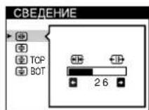
6 CBEDEH (cTp. 12)
BbIOHT Ha dncnne MeHIO CBDEEH nnoctpoKu COBMeueHn UBeTOB NO rOpN3OHTaJI N BepTKaJI n3o6paKeHn.
7 LANG (ctp. 8)
BbIOHT Ha DCNJIeM MeHO LANG nra BbOpa a3bika.

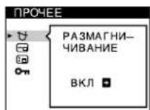
8 NPOOEE (cTp. 15)
BbIOaHT Ha DCINe MeHOIPOOEE dNn NOCTpOKNnapaMeTPOB MOHITOPa. K HmOTHCATC:
pa3MaHnUBaHHe 3KpaHa
N3MeHeHNE NOLOKeHHN 3KpaHHOro MeHIO
-6nokupobka opraHOynpabneHn
BbIXOa
Bb6epnte BblXO, TTo6bl 3aKpbTb MeHIO.
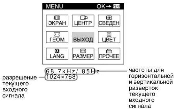
OTo6paXeHne TeKyuIero BXoDHoro cnHaJa
YacToTbI dIra rOpHOTaJIbHO n BepTnKaJIbHO pa3BepTOK TeKUeTeo BXOHNOro CnIHnA h OTo6paKaIoTCa B rIaBHOM MeHIO (MENU). TaXKe OTo6paKaaETcpa3peSeHHe, ecn cInrHaJI COOTBeTCTByeT OJHOMy n3 pExkIMOB DaHHoro MOHITopa, npEaBapNTeJIbHO yCTaHOBJIeHHbIX Ha 3aBODe.
NcNoJIb3OBAHne JxOoiCTnKa
1 BbIeDHTe Ha 3KpaH rJnaBHOe MeHIO (MENU) n BbIeepnte MeHIO, B KOTOpOM Heo6xOaMo BblONHtB NOCTPOkY.
HaxMnte DxKoCTNK OINH pa3 dIa OTobpaKeHnHa 3KpaHe rIaBHO MeHIO (MENU). Pepemeaaite DxKoCTNK BBePx, BHN3, BNeBO INN BnPaBO, YTO6bl BbIbpaTb HxKHOe MeHIO. HaxMnte DxKoCTNK dIa BbIbopa 3JIeMeHTa MeHIO.
2 BbInonHnTe nOCTpoiKy MeHIO.
IpepeeuaTe JxKoNtIK BBeP, Bn3, BLeBO nnn BnpaBO, TTo6bl npOn3BecTn NoCDtpoNky.
3 3aKpoIte MeHIO.
Haxmte JxOcnTk Odn Hpa3, YTo6bI BepHytbcB rnaBHOe MeHIO, N Dba pa3a -DnB O3Bpata B HopmaJIbHi peXIM npocMToPa. EcIn KhoNKe 6bln HaxaTb, TO 3KpaHoe MeHIO aBTOMaTneckn Icye3aet np6bnntenbHO uepe3 30 ckynd.
C6poc HacTpoek
Haxmnte KhoNky RESET (c6poc). Cm. cTp. 16 dnyoJyueHHn noDpo6hbx CbeDeHN O BbIIOJIHeHN c6poca HacTpoek.

Perylnpobka npkoctnn KOHTpactHOCTn n3O6paXeHn
PerynpoBkA npKocTn KOHtpactHcTb BInoJHReTcNocpeCTbOM pa3deJIbHbIX MeHIO RPKOCTb/KOHTPACT.3Tu HacTPOuKN COxpaHHOTcB NAmrtn DnA CnHaNoB, KOtOpBie NOdaKOTcB TEkyuM MOMeT C Bbl6paHHoro BXoDHorO rHe3da.
1 Iepemecnte DkoctnB JIObOM HappaBHeHn. Ha 3kpaHne noBraTc MeHIO RPKOCTb/KOHTPACT.
2 IepemeeaTe DKOHTK BBepx HnBn3 dHaCTPOKn npKOcTn (N BJIeBO Nn BnPaBO dHaCTPOKKn KOHTpactHOCTn (O).
IcnoJIb3OBAHnepeXIma sRGB
EcnB MeHIO LBEt 6bIb BbIbpaH peKIM sRGB, To Ha 3kpaHe noRbIReTc CneDyIOUe MeHIO RPKOCTb/ KOHTPACT.
IpeMeMaTe DxKoNtK BBepX Hn Bn3, TTo6bblBb6paTb prd zBeTOBOr TEMnepaTpby 2.3aTe mepemaTe DxoNCTK BnEBO Hn BnpaBO dHToHHOHaTpoKNzBeTOBOr TEMnepaTpbl.
PnBbINOHNHmTOHOn HAcTPOKu CBETOBO B TEMNepaTpbl HOBbIe UBeTobBle yCTaHOBKN COxpaHOTcB NAMATINJNAKdoN3 Tpex UBeTObBX TEMNepaTp, IN 3JIeMeHT 1 KpaHOro MEHIO N3MeHReTcA CNeDyUOUM O6pa3OM.
·[5000K]→[ ]
·[6500K]→[ ]
·[9300K]→[ ]
PexnCJIOXHA
C NOMOUIbpoexkima CIOXKHAR MOxHO BbINOJIHnTb DOnOIHNTeNbHbIe,6Oone ToUHbIe HAcToPouKuBETA.
1 Nepemeeaante dxoicnB Bepx HnBn3, yTo6bl Bb6paTb pnd zBeTOBOI TemnepaTypl 1. 3aTe m nepemeeaante dxoicntk BJeBO HnBnpaBO dNBA Bb6opa zBeTOBOI TemnepaTypl.
2IepemaeaTe JKOcTK BBePx HnBn3 dNBAb6opa HAcTpaNBaEMoro 3neMeHTa 2.3aTepeMeaaTe JKOcTK BJeBO HnBnpBO dNHaCTpOKnBIAS (ypOBHuePHoro).
Pn3TOM NOCTpaNBAIOCTc TEMhIe 06laCTn 1306paXKeHn.
MOHITOP aBTOMaTnueCKn pa3MaHnHuNbAeTCr, KOrJa Ha Hero BHOBb NODaETCR HAnpJKeHHe.
Ipa pa3MaHnUHbHaMOHHTopa BpyHyIO CHaAna IepemecTNE JKOJCTNK BBepx NIN BHN3 DnBb6opa 3JeMeHaTA (PA3MAHnUHBAHNE). 3aTeM npEpeMeCTNE JXoOCTNK BnpaBO.
3KpaH pa3MaHnHuBaetc npMepHo 3a 2 cekyHdb. EcnnoTpe6yeTc NOBtOpNTb IpOeCC pa3MaHnHuBaHn, 3TO MoXHO CdeLaTb, KaK MnHmym, Ype3 20 MNHyT, dN TOro yTo6bl NOnyHTb HauLyuWn pe3yNbTaT.
I3MeHeHne noJoxKeHH MeHIO
I3MeHnte NIOXKeHne MeHIO, eCNI OHO 3aRopaKnBaet I3O6paKeHne Ha 3KpaHe.
IIN3MeHHeN NOIOXeHMeHIO CHaJaI nepeMeCTnte JKOcTbK BBepx NIn Bn3, YTO6bl Bb6paTb OPN3OHT. IO3.MEHIO)Jn HAcTpoKn No ropn3oHTaJIu IIN EEPNTKAJI.
I03.MEHIO) nHaCTpoKn no BepTKaHn.3aTe m nepemecnte JxOoiCTNK BJeBO nn Bnpabo, TTo6bl npemecNTb 3KpaHHOe MEHO.
KhoNka RESET He DeiCtByeT, KOrda O (BJOKIPOBKA YNPABJIHNAHaxOINTCB NOIOXeHN BKN.
TexHnueckne ocObeHHoctn
IpeyctaHOBJIeHbIe I NOlb3OBaTeMbckne peXIMbl
KordaMOHITOP NOyAeTBxOHOH CnHaJ, OH
ABTOMATUeCKN CORIACOBbIAe TEO C ODNHM I3 peXIMOB
PpeBapHTenbHOn 3aOoDCKo HAcTPOkN, XpaHJUMCBA
nAMrTHMOHITOp, DnO ObecneHeHAR
BbICOKOKaueCTBeHHORIO N3o6paxKeHn B CeHTpe 3kPaHa.
(CM. cnOCK npDeYCTaHOBLeHHbIX peXIMOB B Appendix.)
DnBxOHDbIX CnHAIIOB, HE COOTBeTCTByOuHXn HN ODHOMY
m3 aBOcknxpeXIMOB, C NOMUBo TEXHOJOrn
UNfpoBORO MylbTnCKaHnPoBaHn DaHHORO MOHITOpA
PpON3BOaTcR BCE HAcTPOkN, HeoBXoDMbIe Dn
NoyEHHaYETKOrO N3o6paxKeHn PnI NIOboi
CINxPOHn3aunB Eero JCACTOTHom dMaNa3OHe (NO
ropn30HTaJI: 30-121 KtU, No BeptNKaII: 48-160 T).
Ppi peryNJnpOBKe N3o6paxKeHn DaHHbIe HAcTPOkN
3AHocTcB nAMrTb KAK NOJIb3ObaTeNbCKn peXIM N
ABTomATuHECKN Bbl3bBAHOTcN 3 Hee KaJDbI pa3 ppi
NoIyHeHHn DaHHORO BXoHOrO CnHaHa.
PpmeHne nnoB3oBateNei Windows
PnIb3oBaTeJAM Windows cneJyET o6paTHTbcN K
pyKOBODCTBy NO IcNoJIb3OBAHIO BInDeOpNaTbI INI
BOCNOJIb3OBAtCBaYTNITAMN, NOCTaBNIHEMbIMN C
rpaDnueckoi INaToI, N BiIbPaTa CBMyIO BbICOKyIO N3
BO3MOxHbX YactOT pereHepaUNIN DnI ONTmN3aUN pa60TbI
MOHTOPa.
Функцязнeproc6epeженя
MOHITOP COOTBETCTBYET HOPMAM NO 3HEPROC6EPEKEXHIO, pa3pa6oTaHHbIM VESA, ENERGY STAR N NUTEK. EcIN MOHITOP NOIKIIOHEN K KOMNBIOTepy INI K rpaFneCKO BIDeONTATE TINa DPMS (CNTema npepaun CnHANOB ynpabLeHn IITaHnEM MOHITOP), OH ABTomATueckn cOKpaUaet 3HEpRONOTpe6JeHne B TPN 3Tana, KAK NOKa3aHO HIXe.
YcTpaHHeH HenCnpaBHOCTeI
Ipejde yem o6paTntbCn Cnyk6y TexHueecko IpoedepKKn, O3HaKoMbTeEc b DaHHbIM pa3dEiOM.
ДемперныеΗΝΤΟ
ToHKne IINHn, KOtOpbIe MOryT NOBbIbTcRa Ha 3KpaHe, xapakTePbI dIra MOHITOpOB Trinitron, Ho He ABJIOTcR HeNoJaIKo. 3TO TeHn demNepbHbIX HntEi, KOtOpbIe racr Bn6paunAoepTpHoi peWetKn; Han6Oonee 3aMeTHbIMn OH CTaHOBATcR pN BbIOBe Ha 3KpaH CBETlORo fOHa (obuHNO 6eJoro). ApeTpPhaer PeWetKa - 3TO OueHb BaxHbI 3JeMeHT, KOtOpB I DeJaET 3JEKTPOHHO-JUyEBBte Tpy6Kn Trinitron yHnKaJIbHbIMn I o6ecNeuBaET 60nee INHTeHCINBHe CBeTJIbe ToHa Ha 3KpaHe, 6laoradpAemy N3O6paKeHne cTaHOBITc Rape n OTYeTJIbEE.
3KpaHHbIe coo6eHnA
PnHEnpaBnBHom BXoDHom CnHaHe Ha 3KpaHe NOBNTcOdHO NHXeYKa3aHHbIX COO6eHm.
EcnHa 3KpaHe nOBJIeTc coo6ueHne HET BXOHOFO CnHAJA
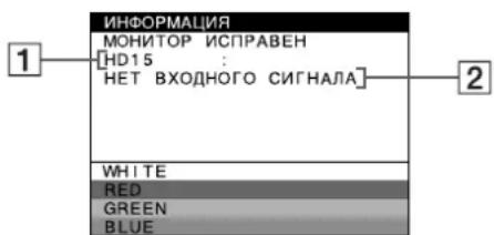
1 BbI6paHHoe BXOdHoe rHe3do
DaHHoe coo6eHne OTo6paXaet BbI6paHHOe TBekyun MOMENT BXoDHOe rHe3do (HD15nnBNC).
2 CoCTOHHBxODHOro CnHaJIa HET BXODHO CnHAJIa
YKa3bIbAeT Ha To, YTO BXOДHо CnHrHaN He NODaETcB BOO6ue NII H e PpINHMaeTc BbIbpaHHbIM BXOДHbIM rHe3dOM.
EcnHa 3KpaHe NOBJIeTc COO6eHne HEONYCTMbI IPAQHueCKN PEXIM
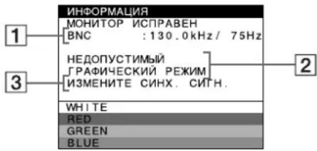
1 BbI6paHHe rHe3do n YactOTbI TeKyuJero BXoJHOrcnHaHa
Dahnoe coo6eHne OTo6paKaet BbI6paHHoe B TeKyuim MOMENT BXoHoe rHe3do (HD15 uIN BNC). Ecm MoHtOp paCnO3Haet YactOTbI TeKyuero BXoHoro CnHana,TO TaXKe OTo6paKaIoTc YactOTbI DnI Ropu3OHTaBHO IN BePTNkaJIbHO pa3BeptOK.
2 CoCTOHNBE BXODHOROCnHaJa HEONYCTMBlI rPAΦNUECKN PEXKIM
YKa3bIbAeT Ha To, YTO BXOJHON CnHAn He COOTBETCTByET XapaKTePncTnKaM MOHTopa.
3 DeiCtBnNo yctpaHEnHIO
Ha 3kpae noBnAeTc coo6ueHne N3MEHNTE CNHX.CINH..Ecnn daHHaM OdeIb yCtHaBaNBae TcB MeCTO CTaporo MOHTopa, BepHnte npexKn MoHTOp Ha MeCTO. 3aTe M HAcTpoTe rpaqNueckn aDAnTep, TaK YTO6bl qactota ropns0HTaJIbHO pa3BepTKn 6blNa B dInana3OHe 30- 121 KU, a AcToTa BepTKaJIbHO pa3BepTKn - B dInana3OHe 48-160 Tc.
IINI NONYEHN IONONHHTeNBbIX CBeDeHN CM. pa3dEIN "CmNTOMbI HeNoaDOK IN DeiCTBnI NO INx yCTpaHEHIO" Ha cTp. 18.
OTo6paXeHHe Ha3BaHnMa MoJeN MoHtOpa, cepuHoro Homepa N DaTbI BbInycka.
B MOMENT NOLUyehnma MOHITOPOM BUNDEOCINHaHaXMMTe JxKoNCTNK Hne OTnyckaIte B TeueHne He MeHee Tpex CEkyHd, YTObblbIEcTn Ha3KpaH INHOpMaunOHoe OKHO dnaDHHo MoJeIMMOHITopa.
Ecnn npo6nema coxpaHReTc, o6paTtecb K
PekomehdyetcI Iopn3oHTaII:1600 ToeK
NoBepTnKaI:1200nnH
CTaHapTaHaI NIOUaIb H3O6paXeHHA
Pn6n.388·291MM(W/B)
N
Pn6J. 364 x 291 MM (W/B)
Yactota pa3BepTKN* Iopn3oHTaJIM:OT 30 do 121K
NoBepTnKaJIi:OT48do160Iu
NapametpbceTeBoro nTaHn
ot 100 do 240 B, 50 - 60 T
2,0-1,0A
Iotppe6nmaMoUHocTb
Pn6n3.145Bt(6e3
noKlHueHHbIX yCtpoiCTB USB)
Pa6o7aTeMnepaTpa 10^ - 40^
T6apntbI Pn6n.502x511x480,3MM
(ω/B/D)
BecPn6n.33Kr

Plug and Play DDC1/DDC2B/DDC2Bi, GTF
BxOJaUe B KOMnJIeKr npHaJdNexKHOCTn
CM. cTp. 6
*PeKoMeHnyeMbIpeXIM CnHxpoHn3aunn no Tropn3OHTaII IN BepTnKaII
-巾nHa HmnyIbCa rOpn3OHTaJIbHO CINHxPOH3aUH 0JXHa 6bIb 6oJIbwe 4,8% 06eero nepnoDa rOpn3OHTaJIbHO pa3BepTK nN 0,8 MKC,B 3aBNCIMOCTN OT TO, KOToPAI N3 HNX 6oJIbWe.
- INHTepBaI MExJy CnHraJaMn ROpN3OHTaJIbHO pa3BepTKIdoJIKeH 6blb6oJIbe2,3MKc.
- INHTepBaJ MExJy CInHaJaMn BepTKaJIbHOJ pa3BepTKn DOJKeH 6bITb 6OJIbWe 450 MKC.
** EcIn BxOJHOn CnHn COOTBeTCTBye TnapaMeTpam GTF (Generalized Timing Formula), TO ONTImaJIbHOe n3o6paXeHne DnI DaCnJe 6yEdt AToTMaUYeckn obecneHuBaTbc cyHKuEeGTF.
KoHCTpykunn xapaKTepunctnMoryt n3MeHrTbc8e3 npedBaPntelbHO ryeDOMHeHn.
Extrainstallingar (OPTION)
Plug and Play DDC1/DDC2B/DDC2Bi, GTF**
Plug and Play DDC1/DDC2B/DDC2Bi, GTF**
If the input signal does not match one of the factory preset modes above, the Generalized Timing Formula feature of this monitor will automatically provide an optimal image for the screen as long as the signal is GTF compliant.
TCO'99 Eco-document

Congratulations!
You have just purchased a TCO'99 approved and labelled product! Your choice has provided you with a product developed for professional use. Your purchase has also contributed to reducing the burden on the environment and also to the further development of environmentally adapted electronics products.
Why do we have environmentally labelled computers?
In many countries, environmental labelling has become an established method for encouraging the adaptation of goods and services to the environment. The main problem, as far as computers and other electronics equipment are concerned, is that environmentally harmful substances are used both in the products and during their manufacture. Since it is not so far possible to satisfactorily recycle the majority of electronics equipment, most of these potentially damaging substances sooner or later enter nature.
There are also other characteristics of a computer, such as energy consumption levels, that are important from the viewpoints of both the work (internal) and natural (external) environments. Since all methods of electricity generation have a negative effect on the environment (e.g. acidic and climate-influencing emissions, radioactive waste), it is vital to save energy. Electronics equipment in offices is often left running continuously and thereby consumes a lot of energy.
What does labelling involve?
This product meets the requirements for the TCO'99 scheme which provides for international and environmental labelling of personal computers. The labelling scheme was developed as a joint effort by the TCO (The Swedish Confederation of Professional Employees), Svenska Naturskyddsforeningen (The Swedish Society for Nature Conservation) and Statens Energimyndighet (The Swedish National Energy Administration).
Approval requirements cover a wide range of issues: environment, ergonomics, usability, emission of electric and magnetic fields, energy consumption and electrical and fire safety.
(continued)
The environmental demands impose restrictions on the presence and use of heavy metals, brominated and chlorinated flame retardants, CFCs (freons) and chlorinated solvents, among other things. The product must be prepared for recycling and the manufacturer is obliged to have an environmental policy which must be adhered to in each country where the company implements its operational policy.
The energy requirements include a demand that the computer and/or display, after a certain period of inactivity, shall reduce its power consumption to a lower level in one or more stages. The length of time to reactivate the computer shall be reasonable for the user.
Labelled products must meet strict environmental demands, for example, in respect of the reduction of electric and magnetic fields, physical and visual ergonomics and good usability.
Below you will find a brief summary of the environmental requirements met by this product. The complete environmental criteria document may be ordered from:
TCO Development
SE-114 94 Stockholm, Sweden
Fax: +46 8 782 92 07
Email (Internet): development@tco.se
Current information regarding TCO'99 approved and labelled products may also be obtained via the Internet, using the address: http://www.tco-info.com/
Environmental requirements
Flame retardants
Flame retardants are present in printed circuit boards, cables, wires, casings and housings. Their purpose is to prevent, or at least to delay the spread of fire. Up to 30% of the plastic in a computer casing can consist of flame retardant substances. Most flame retardants contain bromine or chloride, and those flame retardants are chemically related to another group of environmental toxins, PCBs. Both the flame retardants containing bromine or chloride and the PCBs are suspected of giving rise to severe health effects, including reproductive damage in fish-eating birds and mammals, due to the bio-accumulative processes. Flame retardants have been found in human blood and researchers fear that disturbances in foetus development may occur.
The relevant TCO'99 demand requires that plastic components weighing more than 25 grams must not contain flame retardants with organically bound bromine or chlorine. Flame retardants are allowed in the printed circuit boards since no substitutes are available.
Cadmium**
Cadmium is present in rechargeable batteries and in the colour-generating layers of certain computer displays. Cadmium damages the nervous system and is toxic in high doses. The relevant TCO'99 requirement states that batteries, the colour-generating layers of display screens and the electrical or electronics components must not contain any cadmium.
Mercury**
Mercury is sometimes found in batteries, relays and switches. It damages the nervous system and is toxic in high doses. The relevant TCO'99 requirement states that batteries may not contain any mercury. It also demands that mercury is not present in any of the electrical or electronics components associated with the labelled unit.
CFCs (freons)
The relevant TCO'99 requirement states that neither CFCs nor HCFCs may be used during the manufacture and assembly of the product. CFCs (freons) are sometimes used for washing printed circuit boards. CFCs break down ozone and thereby damage the ozone layer in the stratosphere, causing increased reception on earth of ultraviolet light with e.g. increased risks of skin cancer (malignant melanoma) as a consequence.
Lead\*\*
Lead can be found in picture tubes, display screens, solders and capacitors. Lead damages the nervous system and in higher doses, causes lead poisoning. The relevant TCO'99 requirement permits the inclusion of lead since no replacement has yet been developed.
- Bio-accumulative is defined as substances which accumulate within living organisms.
** Lead, Cadmium and Mercury are heavy metals which are Bioaccumulative.