GDMF520 - Other computer accessories SONY - Free user manual and instructions
Find the device manual for free GDMF520 SONY in PDF.
User questions about GDMF520 SONY
0 question about this device. Answer the ones you know or ask your own.
Ask a new question about this device
Download the instructions for your Other computer accessories in PDF format for free! Find your manual GDMF520 - SONY and take your electronic device back in hand. On this page are published all the documents necessary for the use of your device. GDMF520 by SONY.
USER MANUAL GDMF520 SONY
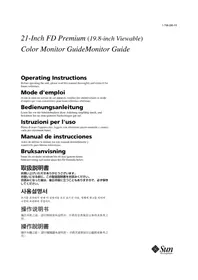
Trinitron® Color Graphic Display
Operating Instructions GB
Mode d'emploi FR
Bedienungsanleitung DE
Manual de instrucciones ES
Istruzioni per l'uso
HCTpykua no 3Kcnlyatau RU
Bruksanvisning
Gebruiksaanwijzing NL
GDM-F520
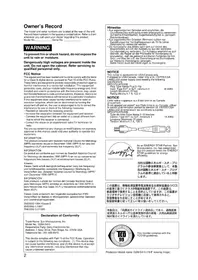
Owner's Record
The model and serial numbers are located at the rear of the unit. Record these numbers in the spaces provided below. Refer to them whenever you call upon your dealer regarding this product. Model No. __ Serial No. ____
WARNING
To prevent fire or shock hazard, do not expose the unit to rain or moisture.
Dangerously high voltages are present inside the unit. Do not open the cabinet. Refer servicing to qualified personnel only.
FCC Notice
This equipment has been tested and found to comply with the limits for a Class B digital device, pursuant to Part 15 of the FCC Rules. These limits are designed to provide reasonable protection against harmful interference in a residential installation. This equipment generates, uses, and can radiate radio frequency energy and, if not installed and used in accordance with the instructions, may cause harmful interference to radio communications. However, there is no guarantee that interference will not occur in a particular installation. If this equipment does cause harmful interference to radio or television reception, which can be determined by turning the equipment off and on, the user is encouraged to try to correct the interference by one or more of the following measures:
-
Reorient or relocate the receiving antenna.
-
Increase the separation between the equipment and receiver.
- Connect the equipment into an outlet on a circuit different from that to which the receiver is connected.
- Consult the dealer or an experienced radio/TV technician for help.
You are cautioned that any changes or modifications not expressly approved in this manual could void your authority to operate this equipment.
EN 55022 Compliance (Czech Republic Only)
This device belongs to category B devices as described in EN 55022, unless it is specifically stated that it is a category A device on the specification label. The following applies to devices in category A of EN 55022 (radius of protection up to 30 meters). The user of the device is obliged to take all steps necessary to remove sources of interference to telecommunication or other devices.
This product complies with Swedish National Council for Metrology (MPR) standards issued in December 1990 (MPR II) for very low frequency (VLF) and extremely low frequency (ELF).
INFORMATION
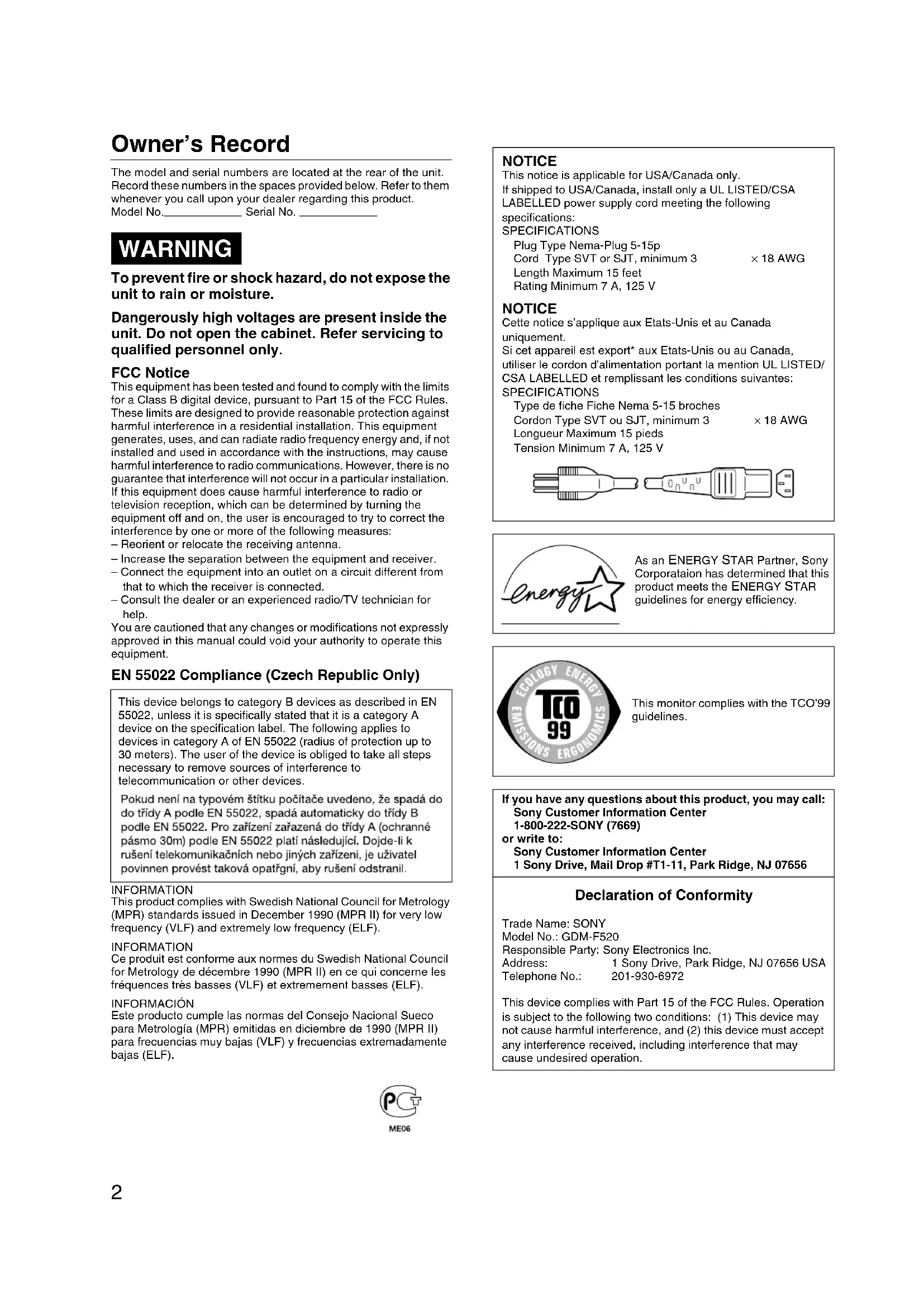
This notice is applicable for USA/Canada only.
If shipped to USA/Canada, install only a UL LISTED/CSA
LABELLED power supply cord meeting the following
specifications:
SPECIFICATIONS
Plug Type Nema-Plug 5-15p
Cord Type SVT or SJT, minimum 3 ×18 AWG
Length Maximum 15 feet
Rating Minimum 7 A, 125 V
NOTICE
As an ENERGY STAR Partner, Sony Corporation has determined that this product meets the ENERGY STAR guidelines for energy efficiency.

This monitor complies with the TCO'99 guidelines.
If you have any questions about this product, you may call:
Sony Customer Information Center
1-800-222-SONY (7669)
or write to:
Sony Customer Information Center
1 Sony Drive, Mail Drop #T1-11, Park Ridge, NJ 07656
Declaration of Conformity
Trade Name:SONY
Model No.: GDM-F520
Responsible Party: Sony Electronics Inc.
Address: 1 Sony Drive, Park Ridge, NJ 07656 USA
Telephone No.: 201-930-6972
This device complies with Part 15 of the FCC Rules. Operation is subject to the following two conditions: (1) This device may not cause harmful interference, and (2) this device must accept any interference received, including interference that may cause undesired operation.
Table of Contents
Setup 3
Adjustments 4
Troubleshooting 6
Specifications 7
Precautions 8
Appendix
- Preset mode timing table
TCO'99 Eco-document Back Cover
- Trin is a registered trademark of Sony Corporation.
- Macintosh is a trademark licensed to Apple Computer, Inc., registered in the U.S.A. and other countries.
- Windows® and MS-DOS are registered trademarks of Microsoft Corporation in the United States and other countries.
- IBM PC/AT and VGA are registered trademarks of IBM Corporation of the U.S.A.
- VESA and DDC™ are trademarks of the Video Electronics Standard Association.
ENERGY STAR is a U.S. registered mark. - All other product names mentioned herein may be the trademarks or registered trademarks of their respective companies.
- Furthermore, "TM" and "®" are not mentioned in each case in this manual.
Setup
1 Connecting your monitor to your computer
To connect to the HD15 input connector
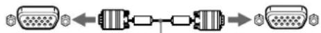
to HD15
video signal cable
(supplied)
to HD15 of the
connecting computer
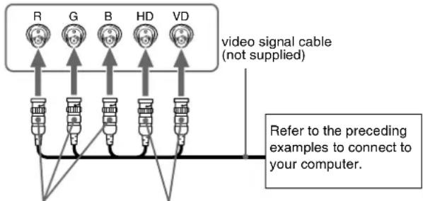
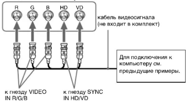
To connect to the 5 BNC connectors
toVIDEO IN R/G/B to SYNC IN HD/VD
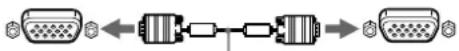
Connecting to a Macintosh or compatible computer
When connecting this monitor to a Power Mac G3/G4 computer, use the supplied adapter if necessary. Connect the supplied adapter to the computer before connecting the cable. If you connect to another version of Macintosh series computer, having 2 rows of pins, you will need a different adapter (not supplied).
2 Turning on the monitor and computer
1 Connect the power cord to the monitor and press the ① (power) switch to turn on the monitor.
2 Turn on the computer.
No need for specific drivers
This monitor complies with the "DDC" Plug & Play standard and automatically detects all the monitor's information. No specific driver needs to be installed to the computer.
The first time you turn on your PC after connecting the monitor, the setup Wizard may appear on the screen. In this case, follow the on-screen instructions. The Plug & Play monitor is automatically selected so that you can use this monitor.
Notes
- Plug and Play is compatible with the HD15 connector only, and not compatible with the 5 BNC connectors.
- Do not touch the pins of the video signal cable connector.
- Check the alignment of the HD15 connector to prevent bending the pins of the video signal cable connector.
To select the input signal
You can connect two computers to this monitor using the HD15 and BNC connectors. To select one of the two computers, use the INPUT switch. The selected connector appears on the screen for 3 seconds.
Note
If no signal is input to the selected connector, NO SIGNAL appears on the screen. After a few seconds, the monitor enters the power saving mode. If this happens, switch to the other connector.
To connect Universal Serial Bus (USB) compliant peripherals
Confirm that the monitor and computer are turned on, then connect your computer to the USB connectors ( ) on the right side of the monitor.
Connect your computer to the square upstream connector ( ) using the supplied USB cable.
If a Windows message appears, follow the on-screen instructions and select "Generic USB Hub".
When connecting your USB compliant peripheral devices (e.g., printer, keyboard, mouse, scanner, etc.) connect the rectangular downstream USB connector (
Note
The monitor functions as a USB hub as long as the monitor is either "on" or in power saving mode.
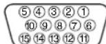
HD15 input connectors
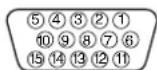
| Pin No. | Signal |
| 1 | Red |
| 2 | Green (Sync on Green) |
| 3 | Blue |
| 4 | ID (Ground) |
| 5 | DDC Ground* |
| 6 | Red Ground |
| 7 | Green Ground |
| 8 | Blue Ground |
| Pin No. | Signal |
| 9 | DDC + 5V* |
| 10 | Ground |
| 11 | ID (Ground) |
| 12 | Bi-Directional Data (SDA)* |
| 13 | H. Sync |
| 14 | V. Sync |
| 15 | Data Clock (SCL)* |
- DDC (Display Data Channel) is a standard of VESA.
Adjustments
Navigating the menu
1 Press the MENU button to display the main menu.
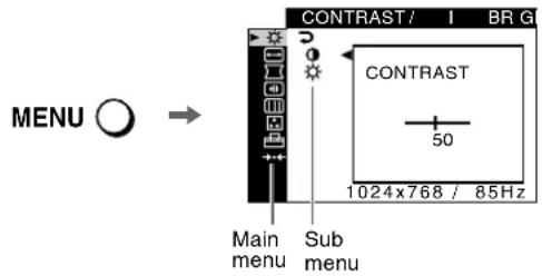
2 Move the control button / to highlight the main menu you want to adjust and press the control button.
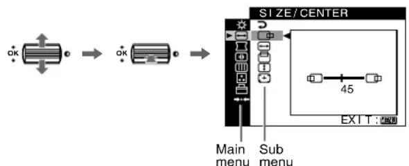
3 Select the sub menu you want to adjust and press the control button.
4 Adjust with the control button.
On-Screen menu adjustments
| Main menu icons and adjustment items | Sub menu icons and adjustment items | ||
| Adjusting the contrast and brightness*1 | Contrast | ||
| Brightness | |||
| ←→ | Adjusting the size or centering of the picture*1 | Horizontal position | |
| Horizontal size | |||
| Vertical position | |||
| Vertical size | |||
| Auto Size Center | |||
| Adjusting the shape of the picture | Rotating the picture | ||
| Expanding or contracting the picture sides*1 | |||
| Shifting the picture sides to the left or right*1 | |||
| Adjusting the picture width at the top of the screen*1 | |||
| Shifting the picture to the left or right at the top of the screen*1 | |||
| RESET: Returns all settings to their factory default settings. | |||
| Adjusting the convergence*2 | Horizontally shifts red or blue shadows | ||
| Vertically shifts red or blue shadows | |||
| Vertically shifts red or blue shadows at the top of the screen | |||
| Vertically shifts red or blue shadows at the bottom of the screen | |||
| RESET: Returns all settings to their factory default settings. | |||
| Adjusting the picture quality Example of Moiré | DEGAUSS: demagnetizes the monitor. | ||
| CANCEL MOIRE: adjusts the degree of moiré cancellation until the moiré is at a minimum.*1 | |||
| LANDING: reduces any color irregularities in the screen's top left corner to a minimum.*2 | |||
| LANDING: reduces any color irregularities in the screen's top right corner to a minimum.*2 | |||
| LANDING: reduces any color irregularities in the screen's bottom left corner to a minimum.*2 | |||
| LANDING: reduces any color irregularities in the screen's bottom right corner to a minimum.*2 | |||
| RESET: Returns all settings to their factory default settings. | |||
Adjusting the picture quality (PICTURE EFFECT)
You can select the most appropriate picture mode from among 3 preset modes by pressing the PICTURE EFFECT button repeatedly.
PROFESSIONAL
For accurate and consistent display color. Choose this for professional desktop publishing and graphic applications.
STANDARD
For images with high contrast and brightness. Choose this mode for commonly used applications, such as spreadsheets, word processing, E-mail, or WEB surfing.
DYNAMIC
For extremely vivid and photo-realistic images. Bright than "STANDARD" mode, choose this for intense entertainment software such as games, or DVD playback.
| Main menu icons and adjustment items | Sub menu icons and adjustment items | ||
| Adjusting the color of the picture | See “: To adjust the color of the picture”. | ||
| Additional settings | On | Protecting adjustment data (CONTROL LOCK) *4 | |
| A | Selecting the on-screen menu language/Confirming the monitor's information LANGUAGE/INFORMATION*3 | ||
| +0 | Changing the menu's position for horizontal adjustment | ||
| 10 | Changing the menu's position for vertical adjustment | ||
| Selecting the color adjustment mode (See “: To adjust the color of the picture.”) | |||
| →+Resetting the adjustments | →←1*1 | Resetting all the adjustment data for the current input signal.* Select “OK”. | |
| →←2*2 | Resetting all of the adjustment data for all input signals. Select “OK”. | ||
*This adjustment is effective for the current input signal.
*This adjustment is effective for all input signals.
* Language Menu
- ENGLISH - NEDERLANDS: Dutch
FRANCAIS: French • SVENSKA: Swedish
- DEUTsCH: German - Pycckn Russian
- ESPANOL: Spanish - 日本語: Japanese
ITALIANO:Italian
^*4 Only the ① (power) switch, EXIT, and ON (CONTROL LOCK) menu will operate.
^*5 The menu items 四 , 四 and 四 are not reset by this method.
: To adjust the color of the picture
The COLOR settings allow you to adjust the picture's color temperature by changing the color level of the white color field. Colors appear reddish if the temperature is low, and bluish if the temperature is high. This adjustment is useful for matching the monitor's color to a printed picture's colors.
Select one of the color temperature setting modes from among 4 modes; EASY, PRESET, EXPERT, and sRGB on (OPTION) menu.
EASY (Default setting)
You can adjust the color temperature from 5000K to 11000K.
PRESET
You can select the preset color temperature from 5000K, 6500K, or 9300K. The default setting is 9300K.
EXPERT
You can make additional fine adjustments to the color by selecting this mode. GAIN (adjusts the bright areas of the screen, while BIAS (adjusts the dark areas of the screen.
| Select for | |
| R | R (Red) BIAS |
| G | G (Green) BIAS |
| B | B (Blue) BIAS |
| →← | RESET |
| Select for | |
| R | R (Red) GAIN |
| G | G (Green) GAIN |
| B | B (Blue) GAIN |
■ sRGB
The sRGB color setting is an industry standard color space protocol designed to correlate the colors displayed on the monitor and those printed. In order to display the sRGB colors correctly ( = 2.2
6500K), select the sRGB mode and set the PROFESSIONAL mode of PICTURE EFFECT (page 4) and your connected computer to the sRGB profile. If you select sRGB, you cannot operate the
CONTRAST/BRIGHT menu adjustments.
To restore the color from the EASY, PRESET, or sRGB modes (IMAGE RESTORATION)
You can restore the color to the original factory quality levels. Before using this feature, the monitor must have been in normal operation mode (green power indicator on) for at least 30 minutes. You may need to adjust your computer's power saving settings. If the monitor has not been on for at least 30 minutes, the "AVAILABLE AFTER WARM UP" message will appear. Also, this function may gradually lose its effectiveness due to the natural aging of the Trinitron picture tube.
Troubleshooting
■No picture
If the ① (power) indicator is not lit
-
Check that the power cord is properly connected.
-
Check that the ① (power) switch is in the "on" position.
The ① (power) indicator is orange
- Check that the video signal cable is properly connected and all plugs are firmly seated in their sockets.
- Check that the INPUT switch setting is correct.
- Check that the HD15 video input connector's pins are not bent or pushed in.
- Check that the computer's power is "on".
- The computer is in power saving mode. Try pressing any key on the computer keyboard or moving the mouse.
- Check that the graphic board is completely seated in the proper bus slot.
If the ① (power) indicator is green or flashing orange
- Use the Self-diagnosis function.
■Picture flickers, bounces, oscillates, or is scrambled
- Isolate and eliminate any potential sources of electric or magnetic fields such as other monitors, laser printers, electric fans, fluorescent lighting, or televisions.
- Move the monitor away from power lines or place a magnetic shield near the monitor.
- Try plugging the monitor into a different AC outlet, preferably on a different circuit.
Try turning the monitor 90^ to the left or right. - Check your graphics board manual for the proper monitor setting.
- Confirm that the graphics mode and the frequency of the input signal are supported by this monitor (see "Preset mode timing table" on page i). Even if the frequency is within the proper range, some graphics board may have a sync pulse that is too narrow for the monitor to sync correctly.
- Adjust the computer's refresh rate (vertical frequency) to obtain the best possible picture.
■Picture is fuzzy
- Adjust the contrast, brightness, and PICTURE EFFECT.
Degauss the monitor. - Adjust the degree of moiré cancellation until the moiré is minimal, or set CANCEL MOIRE to OFF.
■Picture is ghosting
- Eliminate the use of video cable extensions and/or video switch boxes.
- Check that all plugs are firmly seated in their sockets.
■Picture is not centered or sized properly
- Perform the Auto Size Center function.
- Adjust the size or centering. Note that with some input signals and/or graphics board the periphery of the screen is not fully utilized.
- Just after turning on the power switch, the size/center may take a while to adjust properly.
Edges of the image are curved
- Adjust the geometry.
Wavy or elliptical pattern (moire) is visible
- Adjust the degree of moiré cancellation until the moiré is minimal.
- Change your desktop pattern.
Color is not uniform
- Degauss the monitor.* If you place equipment that generates a magnetic field, such as a speaker, near the monitor, or if you change the direction the monitor faces, color may lose uniformity.
- Adjust the landing.
■White does not look white
- Adjust the color temperature.
- Check that the 5 BNC connectors are connected in the correct order.
Monitor buttons do not operate ( appears on the screen)
If the control lock is set to ON, set it to OFF.
Letters and lines show red or blue shadows at the edges
- Adjust the convergence.
■USB peripherals do not function
- Check that the appropriate USB connectors are securely connected.
- Turn the monitor OFF and then ON again, then reconnect USB cable.
- If you connect a keyboard or mouse to the USB connectors and then boot your computer for the first time, the peripheral devices may not function. First connect the keyboard and mouse directly to the computer and set up the USB compliant devices. Then connect them to this monitor.
- Install the latest version of the device driver on your computer. Contact your device's manufacturer for information about the appropriate device driver.
A hum is heard right after the power is turned on
- This is the sound of the auto-degauss cycle. When the power is turned on, the monitor is automatically degaussed for a few seconds.
- If a second degauss cycle is needed, allow a minimum interval of 20 minutes for the best result. A humming noise may be heard, but this is not a malfunction.
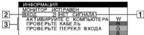
On-screen messages
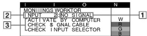
1 If "NO SIGNAL" appears:
This indicates that no signal is input from the selected connector.
2 Shows the currently selected connector.
3Shows the remedies.
- If ACTIVATE BY COMPUTER appears on the screen, try pressing any key on the computer or moving the mouse, and confirm that your computer's graphic board is completely seated in the correct bus slot.
- If CHECK SIGNAL CABLE appears on the screen, check that the monitor is correctly connected to the computer.
- If CHECK INPUT SELECTOR appears on the screen, try changing the input signal.
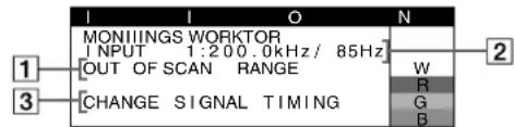
If "OUT OF SCAN RANGE" appears:
This indicates that the input signal is not supported by the monitor's specifications.
2 Shows the input signal frequency.
3Shows the remedies.
CHANGE SIGNAL TIMING appears on the screen. If you are replacing an old monitor with this monitor, reconnect the old monitor. Then adjust the computer's graphic board so that the horizontal frequency is between 30 - 137kHz and the vertical frequency is between 48 - 170Hz .
To display this monitor's name, serial number, and date of manufacture.
While the monitor is receiving a video signal, press and hold the MENU button for more than 5 seconds to display this monitor's information box.
| INFORMATION | |
| MODEL: GDM-F520 | W |
| SER NO: 1234567 | R |
| MANUFACTURED: 2000-52 | G |
| B | |
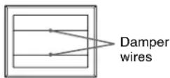
If thin lines appear on the screen (damper wires)
These lines do not indicate a malfunction; they are a normal effect of the Trinitron picture tube with this monitor. These are shadows from the damper wires used to stabilize the aperture grille. The aperture grille is the essential element that makes a Trinitron picture tube unique by allowing more light to reach the screen, resulting in a brighter, more detailed picture.
Self-diagnosis function
This monitor is equipped with a self-diagnosis function. If there is a problem with your monitor or computer(s), the screen will go blank and the ① (power) indicator will either light up green or flash orange. If the ① (power) indicator is lit in orange, the computer is in power saving mode. Try pressing any key on the keyboard or moving the mouse.
If the ① (power) indicator is green
1 Disconnect any plugs from the video input 1 and 2 connectors, or turn off the connected computer(s).
2 Turn the monitor OFF and then ON.
3 Hold the control button upward for a few seconds before the monitor enters power saving mode.
If all 4 color bars appear (white, red, green, blue), the monitor is working properly. Reconnect the video input cables and check the condition of your computer(s).
If the color bars do not appear, there is a potential monitor failure. Inform your authorized Sony dealer of the monitor's condition.
If the ① (power) indicator is flashing orange
Turn the monitor OFF and then ON.
If the ① (power) indicator lights up green, the monitor is working properly.
If the ① (power) indicator is still flashing, there is a potential monitor failure. Count the number of seconds between orange flashes of the ① (power) indicator and inform your authorized Sony dealer of the monitor's condition. Be sure to note the model name and serial number of your monitor. Also note the make and model of your computer and graphics board.
Specifications
CRT 0.22 mm aperture grille pitch, 90-degree deflection, FD Trinitron 21 inches measured diagonally
Viewable image size
$$ \begin{array}{l} \text {A p p r o x . 4 0 3 . 8} \times 3 0 2. 2 \mathrm {m m (w / h)} (1 6 \times 1 2 \text {i n c h e s}) \ 1 9. 8 ^ {\prime \prime} \text {v i e w i n g i m a g e} \end{array} $$
Resolution (H:Horizontal, V:Vertical)
$$ \text {M a x u m i m : H : 2 0 4 8 d o t s , V : 1 5 3 6 l i n e s} $$
$$ \text {R e c o m m e n d e d : H : 1 6 0 0 d o t s , V : 1 2 0 0 l i n e s} $$
Input signal levels
$$ \text {V i d e o} \quad \text {S i g n a l : A n a l o g R G B : 0 . 7 0 0 V p - p (p o s i t i v e) , 7 5} \quad \Omega $$
$$ \text {S Y N C} $$
$$ \mathrm {T T L} 2 \mathrm {k} \Omega , \text {P o l a r i t y f r e e} $$
$$ \text {S y n c} = 0. 3 \mathrm {V p - p (n e g a t i v e)} $$
Standard image area
$$ \text {A p p r o x .} 3 8 8 \times 2 9 1 \mathrm {m m} (4: 3) $$
$$ (1 5 ^ {3} / \mathrm {s} \times 1 1 ^ {1} / 2 \text {i n c h e s}) \text {o r} $$
$$ \text {A p p r o x .} 3 6 4 \times 2 9 1 \mathrm {m m} (5: 4) $$
$$ (1 4 ^ {3} / 8 \times 1 1 ^ {1} / 2 \text {i n c h e s}) $$
Deflection frequency (H:Horizontal, V:Vertical)
$$ \mathrm {H}: 3 0 \text {t o} 1 3 7 \mathrm {k H z}, \mathrm {V}: 4 8 \text {t o} 1 7 0 \mathrm {H z} $$
AC input voltage/current
$$ 1 0 0 \text {t o} 2 4 0 \mathrm {V}, 5 0 - 6 0 \mathrm {H z}, 2. 0 - 1. 0 \mathrm {A} $$
Power Consumption (with no USB devices connected)
$$ \text {A p p r o x .} 1 4 5 \mathrm {W} $$
Operating temper
$$ 1 0 ^ {\circ} \mathrm {C} \text {t o} 4 0 ^ {\circ} \mathrm {C} $$
Dimensions Approx. 497 × 499× 487mm (w/h/d)
$$ (1 9 ^ {5 / 8} \times 1 9 ^ {3 / 4} \times 1 9 ^ {1 / 4} \text {i n c h e s}) $$
Mass Approx. 30kg (66 lb 2 oz)
$$ 2 \mathrm {B} / \mathrm {D D C 2 B i} $$
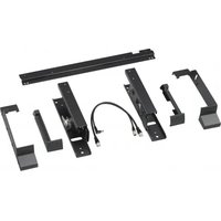
Supplied accessories
$$ \begin{array}{l} \text {P o w e r c o r d} \ H D 1 5 \text {v i d e} \ \mathrm {U S B} \quad \mathrm {c a b l e} \ \text {E x c l u s i v e P o w e r M a c G 3 / G 4 d a p t e r} \ \text {T h i s i n s t r u c t i o n m u a l} \ \end{array} $$
(continued)
Preset and user modes
When the monitor receives an input signal, it automatically matches the signal to one of the factory preset modes stored in the monitor's memory to provide a high quality picture (see "Preset mode timing table" on page i). If the input signals do not match one of the factory preset modes, the monitor automatically provides the most appropriate picture for the input signal that is within the range of the vertical or horizontal frequencies (page 7) corresponding to the Generalized Timing Formula. When the picture is adjusted, the adjustment data is stored as a user mode and automatically recalled whenever the same input signal is received.
Power saving function
This monitor meets the power-saving guidelines set by VESA, TCO'99, and ENERGY STAR. If no signal is input to the monitor from your computer, the monitor will automatically reduce power consumption as shown below.
| Power mode Power consumption* | 1 | ① (power) indicator | |
| normal operation | ≤ 145 W green | ||
| active off*2 | ≤ 3 W orange | ||
| (deep sleep)*3 | |||
1 Figures reflect power consumption when no USB compatible peripherals are connected to the monitor.
2 When your computer enters power saving mode, NO SIGNAL appears on the screen. After a few seconds, the monitor enters power saving mode.
*3“Deep sleep” is power saving mode defined by the Environmental Protection Agency.
Design and specifications are subject to change without notice.
Precautions
Warning on power connections
- Use the supplied power cord. If you use a different power cord, be sure that it is compatible with your local power supply. For the customers in the UK
If you use the monitor in the UK, be sure to use the supplied UK power cable.
Example of plug types
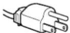


for 100 to 120 V AC for 200 to 240 V AC for 240 V AC only
- Before disconnecting the power cord, wait at least 30 seconds after turning off the power to allow the static electricity on the screen's surface to discharge.
After the power is turned on, the screen is demagnetized (degaussed) for about a few seconds. This generates a strong magnetic field around the screen which may affect data stored on magnetic tapes and disks placed near the monitor. Be sure to keep magnetic recording equipment, tapes, and disks away from the monitor.
The equipment should be installed near an easily accessible outlet.
Installation
Do not install the monitor in the following places:
- on surfaces (rugs, blankets, etc.) or near materials (curtains, draperies, etc.) that may block the ventilation holes
- near heat sources such as radiators or air ducts, or in a place subject to direct sunlight
- in a place subject to severe temperature changes
- in a place subject to mechanical vibration or shock
on an unstable surface - near equipment which generates magnetism, such as a transformer or high voltage power lines
- near or on an electrically charged metal surface
- inside an enclosed rack
Maintenance
- Clean the screen with a soft cloth. If you use a glass cleaning liquid, do not use any type of cleaner containing an anti-static solution or similar additive as this may scratch the screen's coating.
- Do not rub, touch, or tap the surface of the screen with sharp or abrasive items such as a ballpoint pen or screwdriver. This type of contact may result in a scratched picture tube.
- Clean the cabinet, panel and controls with a soft cloth lightly moistened with a mild detergent solution. Do not use any type of abrasive pad, scouring powder or solvent, such as alcohol or benzine.
Transportation
When you transport this monitor for repair or shipment, use the original carton and packing materials.
Display Stand
Do not remove this monitor's stand.
Use of the tilt-swivel
This monitor can be adjusted within the angles shown right. To turn the monitor vertically or horizontally, hold it at the bottom with both hands.
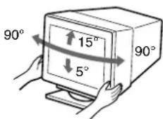
Table des Matieres
Configuration. 3
Réglages. 4
Dépannage 6
Specifications 7
Précautions 8
Appendix
Preset mode timing table
TCO'99 Eco-document. Couverture dos
100a240V,50-60Hz,2,0-1,0A
Consumo de energia (sin dispositivos USB conectados)
Aprox. 145 W
Plug and Play DDC2B/DDC2Bi
FD Trinitron, 21 pollici misurati in diagonale
Circa 388× 291 mm4:3o
Circa 364× 291mm (5:4)
Plug and Play DDC2B/DDC2Bi
Accessorindotazione
IoproToBka K pa6ote. 3
Pereylnopobka 4
YcTpaHHeHHeNCnPaBHOCTe 6
Texnueckne xapaKtepcntukn 7
Mepbippeoctopoxhocn. 8
Appendix
Preset mode timing table
TCO'99 Eco-document. 3aHnKpblka
TrinisperactpupobahnA ToproBa Mapka Sony Corporation.
Macintosh ABnTcT TopoBm MapKo Apple Computer, Inc., 3apernctpopobahno B CUSA n dpynx cTpaHax.
Windows MS-DOS RNAHOTC 3aepnrctpnpbAHHbIMTTOPBOBIMMapkamn Microsoft Corporation B CUIA n dpyrins cTpaHAn.
- IBM PC/AT v VGA ABNIOCT3apeHCTpnpoBaHHbIMT TopROBIMn Mapkam IBM Corporation B CUSA.
VESA U DDC ABJHOTCA TropOBbIMn MapKaMn Video Electronics Standard Association.
ENERGY STAR ABnAeTcMapKo, 3aperncTpnpoBaHHOB CUSA.
OctaIbHbHe HsBaHnIPOyKDyTOb, yONOMHyTBe B 3OTOM DOKYMEnTe, MORYr ABNtBc3 3apeNtPnpOBaHHbIM TopRObbIMu MPaKMn NIN TOpRObbIMu MPaKMn COOTBECTBYOuNX BJaIenJIeB.
BdaIbHeMcMbOJIb“TM"H“@”He yNOMHaOTcB 3TOM pyKOBOdCTBE.
Pojrotobka k pa6oTe
1 NpoknueHne MOHTopa K KOMnbIOTepy
IoiKnIIOHcHHeK BxOAnHomy pa3bemy HD15
K HD15 Ka6eB BuDeocnHana K pa3bemy HD15 (BXoHT B KOMNNEKT) noKnIOuAemoro KOMNbHOtepa
IIOKJIIOHHeHcK 5 pa3beMaB BNC
IopKJIoueHne K KombIOTepy Macintosh nM COBMECTHMOMY C HIM
PnnoKIOHcHmN 3TOO MOHITopa KOMNbIOTepy Power Mac G3/G4 nCOnNoB3yIe Pnnp Heo6xOIMOCtN npnilaraembl aadanTep. BxoJnniB KOMnNEKT nepeXoHNK Heo6xOIMo NOKNHOaTB KOMNbIOTepy DO noKnHOeHn Ka6JIa. Pnnp NoKDNOHcH N DpyHM KOMNbIOTepam cepnn Macintosh, KOtOble ImeOT pa3bEmbl C DByMaN pRJaMNI WtBpBKO, HEO6xOIMMO NcONb3OBA TbDpyrO nepExoDNHK (He BXoINT B KOMNJIeKT).
2 BkJIIOUeHHe MOHITopa N KOMIbIOTepa
1 NODKJIIOHTe Ka6eJb NTaHnK MOHNTOpY HAXMITE KONKY NITAHN ①, YTO6bI BKNIIOHTb MOHNTop.
2 BkIIOHTe KOMNbIoTeP.
CneuaHbHbe npaBepbHe Tpe6yTOc
DaHHb MOHITOP OTBeaET Tpe6oBaHnM CTAndapTa DDC" Plug & Play, y KOMNtBOpTep ABOTMaTHeCKN ObHApYKnBAeT BCO INHΦOpMAuHnO MOHITope. Heo3aTeNbO yCtHaABnBaTb Ha KOMNtIePe kKaKeNn60 cneuaNaHbIe dpaIeBpbI.
Pn npBbOM BkIIOUeHm NIK nocJe NOKKIOUeHm MoHtOpa Ha 3KpaHe MOxET NOBtCBdNAnorOBoE OKHO pOrpAmbl yctAHOBKn. B 3TOM Cnyae cNeyTe yKa3AHm Ha 3KpaHe. MoHtOp Plg & Play BbiBpaETcABToMaTHeckn, YTO No3BOJrER cpa3y HauTaB er NCNoJIb30BaTb.
PpmeaHn
- Φυнкυη Plug and Play pa6oTaet TOnbko c pa3bEmOM HD15 n He pa6oTaet C nTbIO pa3bEmAMn BNC.
He npikacaiTecb K Wtbypkam pa3bema Ka6eBnDaeocirHaia.
PnOBeBpTe npAunBbHocCT bpacnoNoXeHH pa3bema HD15 nIpeoTbpaueHH cr6aHH wTbipbKOB pa3bema ka6eHH BnDEOCIRHLA.
Bb6op BxOndoro CnHana
K DaHHOMy MOHHTOpy MoXHO NOkKnOChuTb Dba KOMNbIOTepa,
ncnOB3yra pa3bEmbl HD15 n BNC. BocnoB3yntecb
nepeKIOUaTeJIem INPUT, YTO6bl Bb6paTb OAnH n3
KOMNbIbETopB. Bb6paHHe rHe3Do NOBBAJeTCa Ha 3kPaHa H
3 cKeYnDbl.
PpmeaHne
EcJn Ha BblbpaHOM BxOe OTCyTCTByET CnHAn,Ha 3KpaHe
noBBAETc coo6eHne HET CnIHANA. Ype3 HeckonbKO cKeYND
MOHTop nepExoINT B pexm 3KoHOMm 3Heprn. B noDobHom cnUyae
pepeKnHOTecb Ha dpyroB BXoD.
NoKJIoueHne nepnepnHbIX ycTpoiCTB, COBMeCTnMbIX co cTaHaprTom USB (yHNBepcaIbHa nocJeDoBaTeIbHa IuHa)
Y6eIntecb TOM,TO MOHITOP KOMNBIOTep BKJIIOUeHbl, 3aTEM NOKIIIOHTe KOIMBIOTep K pa3beMaM USB (a npabO NaHei MOHITopa.
IopKnIOHTe KOMNbIOTep K npmOyroNBHomBy BXoHOMpya3bemy()c nOmoBIO npnlaraeMoro Ka6enr USB.
Ecni Ha 3kpahe NoBHTcNoo6ueHne Windows, cNeJyTe yka3aHnM Ha 3KpaHe N bIb6epNte "Generic USB Hub" (YHBepcanbHbI KOHJeTpAToP USB).
PnnoKIOHEnu USB-COBmecTmbx nepnOpepnHBx yCTpoiCTB (HaepnMep, npnHTepa, KnaBnAtpbl, Mblu, cKahepa nT.D.) noKnIOHNTe npAmoyroIbHb BxOHO pa3bEm USB
PpmeaHne
MOnHTop MoKet pa60TaTb KaK KOHcHTpaTOp USB TOnbko B pexImax "on" (BKn.) INN 3KOHOMIN 3Heprn.
Bxohbpepa3beMbHd15
Moxho Bb6paTb OINH NTpex HanboJeepoOaunx
npBaPteJIbHO yCTaHOBLeHHbIX pExmOB, oecneuBaIOUnx
HaNBbcIe KaEcTB0 N3O6paKeHn, PyTeM
noCleDoBaTeBHorO hXaTnK HONKn PICTURE EFFECT.
■PPOΦECCNOHAJIbHOE
Дя obecneueHЯToOHcTn n Cta6bNbHOCTn UBETOB DnCnner. Bbl6epnte 3TO pexm dIra pa6oTBc InpocceccnoHaJIbHbIMn HAcToJIbHbIMn m3daTeJIbCKMn CnCTeMaMn n rpaΦuYeCKMn npInIOKeHnAMn.
CTAHAPTHOE
Ди n3o6paxeHn C BbICOKO KOnTpaCTHO IN RPKocTBIO. Bbl6epnte 3TOPT pexIM dna pa60ToC obhIM npINOxEHMA, TaKIM KaK 3NeKTPOHHBte Ta6nUbl, TeKCTOBBI peDAkTOp, 3NEKTPOHHA NOHTa INI Web-6pay3ep.
■DINHAMMUECKOe
Дяоуеньяркицьетовизобрахенисфотографпунecков TOHOCHTBIO.; CBeTaВЗТМ ржиме рчe,ЧEMВ pexIMe "CTAHДAPTHOЕ",нэтOMонИСпОпьзУТСДЯТаКИ pazBNekeTeBJbHbX пriNLOжEHСбОБЛшIM KONUЧECTBOM rpaФики,ΚΑΚΙΝρБΙΝΙΝΟΝΡιЗВЕDEDEDHе DVD.
3 BbIepeTe 3JIeMeHT NOmEHo, KOtOpbi Tpe6yeTc HAcTpOuTB, HAXMITE KONky ynpaBHeHn.
4 BbINOJIHnTe HAcTpOy C NOMOuBIO KHOJKN ynpaBHeHHa.
YcTpaHHe HEnCnPaBHOCTeI
HETn3o6paKeHHN
Ecnn uHdNkAToP ① (nntaHne) He rOpNT
- PpOBepbTe, npaBnIbHo nI NOkJIIOUeH Ka6JIb NITaHn.
- PpOBepeTe, HaxoIHTcA IIN BbIKNIOvATeIb ① (nITaHHe) B NOJOKeHm "on" (BKn.).
HdkaTop nTaHn ① ropnt opaHKeBbIM
Y6eIntecb, YTO Ka6eBn BInDeOcHnHa NoNkIIOueH npaBnJbHO, IN BCE pa3bEmbl HaexKHO BCTaBnEhbl CBON IHe3da.
- Y6eIntecb,чTo nepeKJIouaTeIb INPUT cTouT B npabInbHOM nIOJKeHn.
Y6EaNTecb,HTO Hm OIN M3 WtBIPbKOBBIX KOHTAKTOB BnDEokaBnHd15 He ABnRETCn 0sOrHyTbM n He yTONJIEN BNYTpB BNKN.
- PpOBepeTe, HaxoIITcA IIN BbIKIIOUaTeIb KOMNbIOTepa B NOJOKeHn "on" (BKn.).
KOMNbIbOTep HApOJNTCBpeXIMe 3KOHOMMn 3HEpRn. Nonpoobyte HaKaTb NIObYko HKnBnUy HaKnBaNAtype KOMNbIbOTepa INI nepeBnHyTb MbIuB.
- Y6eIntecb, yTO rpaΦnueckn aanTep npaBnHOn nHaedxHO 3akpePnEHN B pa3bEme NOKIIIOUeHnK UINHe.
Ecnn HndkaTOp nTaHnA ① (nTaHne) rOpNT 3eJeHbIM mN MrraET opAHKeBbIM
-IVcnoIb3yIte yHKcuIO caMOHaHOCHTKn.
CkaKn,doXKaHHe,BONHOo6pa3HbIE KOe6aHnNnn NOMEXN 306paKeHH
- IV3OInpyyTe n yctpaHnTe IIO6bIe NOteHcuaNbHbIe NCTOCHNK 3NEKTPUeCKNX INM MaHTNHbIX NOJIe, HApNMeP, DpyTne MOHnTOpbl, Na3epHbIe NpHTpeK, 3NEKTPuCHeCKNe BHTnIaTOpbl, fNoycpecHeTHbIe NaMnbl INIeTeneB3Opbl.
- OToDBNbTe MOHITOp NODaJIbSe OE TINHm 3JNEKTPoNTaHnI YCTaHOBnTE BO3Je HrO MaHHTbI KpaH.
-Nonpo6yIte NIOKNIOHTb MOHITOP K dpyro cTeBOI PO3ETKe, XeNaTeBHO OT dpyrOro KOHTypa. - Nonpo6ynte NOBepHyTb MOHtOp Ha 90^ BnEBo Nnn BnpaBO.
- O6paTInTeCb K pyKoBOJCTBy NO rpaDmUeCKOMy aAaNTepy, YTObIb npOBeRnTB, npaBnJIbHbE IIN npaMaTePbI yCTaHOBNeHbI dnn MOHHTOpA.
YIOCTOBeBpTecb B TOM, YTO rpaHneckn peXm n qactota BXoHoro CnHana COOTBeTCTBYIOT XapaKTEPNCHKAM MOHTopa (cm. pa3den "Preset mode timing table" Ha cTp. i).Дaxe B NOxOJaEM QACTOTOM Dnana3OHe HeKOToPbI rpaHneckne aanTepebl NODaOT CnHsKOM y3Kn JnA KOPKETHO CNHXPOHN3aun MoHTOPa CnHXPOHN3uPyUOUn MMNyIbc.
IIOCTPONTe YACTOTY pEREHEpaM KOMbHOTepa (CACTOTY BEPTKAbHoB pa3BePTKn) dnn NOnyHeHn ONTImaJIbHOrO m3O6pAbKeHH.
Heeyekoe n3o6paXeHne
- Пдстpoи Te KOHTpactHocTb,ApKocTb nФункцИ PICTURE EFFECT.
- BbIOnHnTe pa3MaHnHuBaHne MoHInTopa.*
- OTkoppeKtnpyte CTenbH yctpaHeHMy ApaBorO fOHa, noka OH He byet CbeNe DO MmHMyMa, IINy YCTaHOBnTE JnnpaMeTpA IOJADJIeHNE MYAPA 3naueHne BblKn.
"TeHn"Ha n3o6paXeHm
He nCnoB3yTe yDnHnTeN BnDeOka6ene N KOMMyTaOpbBnDeOcRHaHa.
-Пюовьт,наджно Ли 3akpenneHbI B CBOx rHe3dax BCE pa3beMbl.
HenpaBnIbHbIe ceHTpOBKa nI npa3MeP n3o6paXeHn
BbINOHNHe cyHKcHIO ABTO-Pa3Mep-LeHTp.
IIOCTpoTe pa3MeP HIN OTUeHTpnpyIte N3O6paKeHne. CnEduT NMeTb B BuY, YTOB COeTaHIM BXoDhX CNrHaNOB C onpeJenEHBMn rpaFneCKMm PnAtaMn Kpaar 3KpaHa McNoNb3yOTcH e NoNHOCTbO.
Cpa3y nocle haxatn KhoNkn NITAHIN, I3O6paxeHne HekToTopoe BpeM NoCTpanBaETcNo pa3mepu Y eHTpy 3kpaHa.
KpaHn3o6paXeHHN NCKpNBHeHbI
HepaBHomepHaOkpaKau3o6paKeHHA
- BbINONHInTe pa3MaHnUHbAHe MOHTOpa. * OndopOdHocTb BbTa MoKet HApUaTbCBA T Eex Cnyuayx, KOrDa B6N3n MOHTOpa HaxoTATc NcToHnKm MaHTHOrO NOI, TaKne KaK rPOMKOrOBOPrTeII, INI pR NoOBpOte MOHTOpA.
- OTKOPpeKtynpe pa36baHncnpoBky ZbTa no yrnaam 3kpaHa.
■BeBbIuBETHe BbIrJaNT6eBbIM
- PoiDCTpoIe TcBETOByIO TEMNepaTpy.
- Y6eIntecb, yTO IaTb pa3bEmOB BNC noqKIOueHbB npabINbHom npaKe.
KHONKMOHUTOPaHEpa6oTaOT(Ha3KpaHe NOBJIETCA
EcnnyKn6IOKnOBKnOprAHOyPnABHeN BKNIOyeHa -noJXeHNE BkJI, nepeBnTe ee B noJoxHe N BblKI.
KpaChbIe HnHnEOTTeHNIO KpaHm6yKBHnHnHn·PiOCTpoTe COBMeueHne UBeTOB.
He pa6oTaIOT nepHΦepnHbIe ycTpoIcTba USB
- Y6eIntecb, yTO COOTBeTCTBMyUne pa3bEmbl USB npabInbHO NOdklOueHb HnHaJeKHO 3aKpEnHebl.
- BbIKJIOHHTe MOHITOP, a 3aTEM CHOBA BKJIOHTe. 3aTEM NOKJIIOHTe Ka6eIb USB.
EcnnBnepBbIe NOcOeHNHtB KnaBnAtpy ININMbIbK pa3bEmAM USB, a 3aTeM 3aRpy3ntb KOMNbIOTeP, OHN MOrYr He pa6oTaB. Chauana NODKnIOUHTe KNaBnATpy IN MbIbH ENOpceDCTBeHHO KOMNbIOTepy INpOn3BeINTe HAcTpoKy USB-COBMeCTmBx yCTPOINCTB. 3aTe NODKnIOUHTe INX K MOHITOPy. - YcTaHOBnTe Ha CBoi KOMMbIeTp NocEaHIOU BepCnIO DpaIBepe yctpoCTBa. ObpaTInTeCb K I3rTObTIeNIO UcTPOCTBa 3a DOIOHNHeTbHoi HnFopMaueNe O TpE6yEmoM DpaIBepe yctpoCTBa.
Cpa3y nocne BkIIOueHn MOHTopa pa3daeTc HnpoDOnKntBHOe rydeHne
3TOT 3ByK CONyCTByeT npOceccy aBtOMaTHueckoro paMaHmHbAHn. Iocne BKnIOUeHnI nHTaHnB TteHeHn HECKoJIbKnx CekHyd npOcXoDnT aBtOMaTHueckoe paMaHmHbAHne Tpy6k MoHtota.
* Ecnn Notpe6yETcnaobTOpNTb npoucc pa3MaHmHBaHn, 3To MoXHO CDeNaTb KaK MHNMyM Yepe3 20 MNHT, dNr TOrO YTO6bI NOnyTuHnYuHn pe3yJbTaT. Ydrau nn 3Byk, KOTOpBn CblIeH, He ABnETc HEnCnpABHOCTbHo.
3KpaHHbIe coo6ueHnA
1EcHnHa3KpaHe NOBbEeTcAo6eHne“HET CUNHAJIA”
Yka3bIbAeT Ha To, YTO BXOJHOH CNrHaJI He IOnaetcBbl6paHHbIM BXOJHbIM THe3dOM.
2OTo6paKaet BbI6paHHoe B TeKyuMOMeHT BXoDHOe THe3do.
3OTo6paKaet DeiCTBnNo yctpaHeHIO.
- Ecni Ha 3kpahe noBnHcTc coo6eHne AKTNBUPYITE C KOMNbIOTPEA, nonpo6yIte HaxaTb IIO6yo KnaBnUHa KaMnbiTepe nIi nepeMeCTntbMbIu b y6eINTecb, YTO Nnata rpaQHeCKrO aAnTepa KOMnbiTepe HAdexHo BCTabJIeHa B rHe3Do WInHb.
- EcnnaHa 3KpaHe nOaBnIeTc coo6eHne IPOBEPbTE KABEJIb, npOBepbTe, npabunbHO JIM MOHITOp noKnIOueH K KOMBIOTepy.
- EcIn Ha 3Kpahe NoBnEeTc COo6eHne IPOBEPbTE INPEEKI BXOJa, nonpo6yTe N3MeHHTb BXoHoi CnHAn.
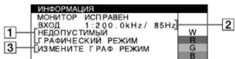
1EcHnHa3KpaHeNoBnRETCoO6eHne "HEONYCTNMBI IPAANUECKNIPEXIM"
Yka3bIbaeHaTo,HTO BXoHON CnHaN He COOTBeTCTByET XapaKTePncTnKaM MOHtOpa.
2OTo6paXeHHe YacToTb BXoDHorO CnHaHa.
3OTo6paKaET DeIcTBnNo yCTpaHeHIO. Ha 3KpaHne nOBnEeTc COo6ueHHe N3MEHNTe IPAΦ PEXHM.Ecn daHHa MoJe b ycTaHaBnBaeTc BMeCtO CTaporo MOHTopa,BePHTe npexHm MOHTop Ha MeCtO.
3aTeM HACTPOIte rpaDnueckm aanTep, TaK YTO6bI cactota roPOnoHTaBHO naiBa B dana3OHe 30-137 KrA auctota BEpTNKaIbHO pABeRtKn -B dana3OBe 48-170 Tc.
OTo6paXeHHe Ha3BaHnM OMeJI MOnHTopa, cepHOro HOMepa N DaTbI BbInycka.
B MOMENT NOJUeHnA MOHITOPOM BUNDeOcHnHa n HAKMITE KHOKNY MENU n He OTnyckaTBe TteueHne He MeHee 5 cekyhd, YTo6bI BBIECTN Ha3KpaH
| Иннорм控制系统 | |
| MODEL : GDM-F520 | W |
| SER NO : 1234567 | R |
| MANUFACTURED : 2000-52 | G |
| B | |
HOpMaIOHOHe OKHO DnAHHo MOeIN MOHTopa.
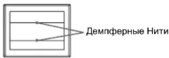
ДемпорнынТи
3TN INHIN He CBnDeTeNbCTByOT O HEnCnpaBHOCTNI
ABJIOTc8O6bIHNbIM 30PfEKTOM 3NeKTPoHHo-NyHeBbIX Tpy6OK
Trinitron, KOTOpBJe yCTaHaBJIbAocTcB DaHHbIX MOHITOPax.
3TO TEHN DeMnFepHbIX HHTe, KOTOpBJe racrT Bn6paMuO
aneptypOno peWetKn. AneptypHaer peWetKa - 3TO OChb
BaxhbI 3JEMENT, KOTOpBJe DnAeAET 3NeKTPoHHo-NyHeBbIE
tp6kN Trinitron YnHKaNbHbIMN I oBeCeNuBaET 6Oone
INTeHCMBIe CBeTbIe TOHa 3KpAne, 6NaOrapar YeMy
1306paXeHne cTaHOBITcApue N OTYeTTNBee.
100-240B,50-60Γu,2,0-1,0A
IOTpe6nemar moohocb (6e3 noKnueHbix yctpoicTB USB)
Pn6J.145B
Pa6oHaTempepaTpa
10^ - 40^
Γa6apntbI Pn6JI.497 ×499×487MM(U/B/Γ)
Maccn 30K
Plug and Play DDC2B/DDC2Bi
BxOaIeB KOMnJIeK TpHaADJeXHOCTN
Ka6eJIb nHTaHn
KaebbBnDeocnHaJHa HD15
Ka6enb USB
CneuaJIbHbI nepeXoDnK K Power Mac G3/G4
HaTcToaH NHTpyKUN no 3KcnnyatauN
PpeyctaHOBJIeHHbI n noJIb3OBaTeMbckn peKmbl
Pnpnpnme BxOHORO CnHana MOHTop aBTOMaTHueckn
COrnAOBOBbIaE rO cOHN m3peXMMOB, npeDbaPnteNHO
yCTAHOBENHHbIX Ha 3aBOe N xpaHAnuXcR B NaAMrN MOHTopa, dNp
06ecneHeyn BbICoKOKaQueCTBeHHORo N3o6paXehn (CM. p3aDen
"Preset mode timing table" Ha cTp. i). EcnN BxoONbIe CnHaNJI He
COOTBECTBYOT HN ONDOMY IN 3aBODCKIN PEKHMOB, MOHTOP
ABOMATNuCeKn NObiprae T AnbOJe eNoXoAun PeKIM dNp
BXOHOrCmHANA, HAXOJUeROC B Dnna3OHe cACTOT
ROP3OHTaJIbHoi N BeptNKaIbHoi pa3BePTKN (CTp. 7), B
COOTBECTBn CfpOpMynO GTF (Generalized Timing Formula). Pnp
perynopBKe N3o6paXehn DAHbIe HAcTPOkN 3aHOCArT B naAMrT
KAK NoIb3OBeTbckM peXMM I ABTOMaTHueckn Bb3bIAIoTcN 3
Hee KaxDbai Paar npOnyEHnn DaHNOr HOxOHOr CnHana.
On-screen Menu-installingen
Plug and Play DDC2B/DDC2Bi
If the input signal does not match one of the factory preset modes above, the Generalized Timing Formula feature of this monitor will automatically provide an optimal image for the screen as long as the signal is GTF compliant.
TCO'99 Eco-document

■Congratulations!
You have just purchased a TCO'99 approved and labelled product! Your choice has provided you with a product developed for professional use. Your purchase has also contributed to reducing the burden on the environment and also to the further development of environmentally adapted electronics products.
Why do we have environmentally labelled computers?
In many countries, environmental labelling has become an established method for encouraging the adaptation of goods and services to the environment. The main problem, as far as computers and other electronics equipment are concerned, is that environmentally harmful substances are used both in the products and during their manufacture. Since it is not so far possible to satisfactorily recycle the majority of electronics equipment, most of these potentially damaging substances sooner or later enter nature.
There are also other characteristics of a computer, such as energy consumption levels, that are important from the viewpoints of both the work (internal) and natural (external) environments. Since all methods of electricity generation have a negative effect on the environment (e.g. acidic and climate-influencing emissions, radioactive waste), it is vital to save energy. Electronics equipment in offices is often left running continuously and thereby consumes a lot of energy.
What does labelling involve?
This product meets the requirements for the TCO'99 scheme which provides for international and environmental labelling of personal computers. The labelling scheme was developed as a joint effort by the TCO (The Swedish Confederation of Professional Employees), Svenska Naturskyddsforeningen (The Swedish Society for Nature Conservation) and Statens Energimyndighet (The Swedish National Energy Administration).
Approval requirements cover a wide range of issues: environment, ergonomics, usability, emission of electric and magnetic fields, energy consumption and electrical and fire safety.
The environmental demands impose restrictions on the presence and use of heavy metals, brominated and chlorinated flame retardants, CFCs (freons) and chlorinated solvents, among other things. The product must be prepared for recycling and the manufacturer is obliged to have an environmental policy which must be adhered to in each country where the company implements its operational policy.
The energy requirements include a demand that the computer and/or display, after a certain period of inactivity, shall reduce its power consumption to a lower level in one or more stages. The length of time to reactivate the computer shall be reasonable for the user.
Labelled products must meet strict environmental demands, for example, in respect of the reduction of electric and magnetic fields, physical and visual ergonomics and good usability.
Below you will find a brief summary of the environmental requirements met by this product. The complete environmental criteria document may be ordered from:
TCO Development
SE-114 94 Stockholm, Sweden
Fax: +46 8 782 92 07
Email (Internet): development@tco.se
Current information regarding TCO'99 approved and labelled products may also be obtained via the Internet, using the address: http://www.tco-info.com/
■Environmental requirements
Flame retardants
Flame retardants are present in printed circuit boards, cables, wires, casings and housings. Their purpose is to prevent, or at least to delay the spread of fire. Up to 30% of the plastic in a computer casing can consist of flame retardant substances. Most flame retardants contain bromine or chloride, and those flame retardants are chemically related to another group of environmental toxins, PCBs. Both the flame retardants containing bromine or chloride and the PCBs are suspected of giving rise to severe health effects, including reproductive damage in fish-eating birds and mammals, due to the bio-accumulative* processes. Flame retardants have been found in human blood and researchers fear that disturbances in foetus development may occur.
The relevant TCO'99 demand requires that plastic components weighing more than 25 grams must not contain flame retardants with organically bound bromine or chlorine. Flame retardants are allowed in the printed circuit boards since no substitutes are available.
Cadmium**
Cadmium is present in rechargeable batteries and in the colour-generating layers of certain computer displays. Cadmium damages the nervous system and is toxic in high doses. The relevant TCO'99 requirement states that batteries, the colour-generating layers of display screens and the electrical or electronics components must not contain any cadmium.
Mercury**
Mercury is sometimes found in batteries, relays and switches. It damages the nervous system and is toxic in high doses. The relevant TCO'99 requirement states that batteries may not contain any mercury. It also demands that mercury is not present in any of the electrical or electronics components associated with the labelled unit.
CFCs (freons)
The relevant TCO'99 requirement states that neither CFCs nor HCFCs may be used during the manufacture and assembly of the product. CFCs (freons) are sometimes used for washing printed circuit boards. CFCs break down ozone and thereby damage the ozone layer in the stratosphere, causing increased reception on earth of ultraviolet light with c.g. increased risks of skin cancer (malignant melanoma) as a consequence.
Lead**
Lead can be found in picture tubes, display screens, solders and capacitors. Lead damages the nervous system and in higher doses, causes lead poisoning. The relevant TCO'99 requirement permits the inclusion of lead since no replacement has yet been developed.
- Bio-accumulative is defined as substances which accumulate within living organisms.
** Lead, Cadmium and Mercury are heavy metals which are Bioaccumulative.