Be Quiet! Dark Base Pro 900 - Desktop Computer

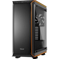
Dark Base Pro 900 - Desktop Computer Be Quiet! - Free user manual and instructions

Find the device manual for free Dark Base Pro 900 Be Quiet! in PDF.

📄 96 pages English EN 💬 AI Question
Notice Be Quiet! Dark Base Pro 900 - page 6

User questions about Dark Base Pro 900 Be Quiet!

0 question about this device. Answer the ones you know or ask your own.

Ask a new question about this device

L'email reste privé : il sert seulement à vous prévenir si quelqu'un répond à votre question.

No questions yet. Be the first to ask one.

Download the instructions for your Desktop Computer in PDF format for free! Find your manual Dark Base Pro 900 - Be Quiet! and take your electronic device back in hand. On this page are published all the documents necessary for the use of your device. Dark Base Pro 900 by Be Quiet!.

USER MANUAL Dark Base Pro 900 Be Quiet!

We are delighted you have chosen to buy our Dark Base PC case. Please read the information here and carefully follow all the instructions prior to installation. Should you have further questions, please contact our customer service. See contact information in the manufacturer’s details section. Warranty ∙ 3-year manufacturer’s warranty for the consumer (original purchase from authorized be quiet! dealers only) ∙ Your original receipt of purchase will be required before warranty services are rendered. Please store it carefully. ∙ Manipulationsand/ortechnicalmodicationsofanykind,ordamageduetotheapplicationofmechanical force, will void your warranty. ∙ To read the warranty terms and conditions in full, see Service/Warranty Conditions on our website at bequiet.com. Our General Terms and Conditions of Business also apply. For details please refer online under bequiet.com. Manufacturer’s details Listan GmbH & Co. KG | Biedenkamp 3a | 21509 Glinde | Germany Visit the contact section on bequiet.com for the right regional service information. Monday through Friday 09:00 – 17:30 (UTC+1) Tel. 0049 40 736 7686 - 44 Fax 0049 40-7367686-69 Email: service@bequiet.com Website: www.bequiet.com Copyright ∙ You are not allowed to reproduce, disclose, publish or store the contents of this documentation, or excerpts of it, without the prior written consent of Listan. ∙ be quiet! is a registered trademark of Listan GmbH & Co. KG. Other products and company names mentioned in this documentation may be the brands or trademarks of their respective owners. ∙ In accordance with company policy, all Listan products are subject to ongoing development. Listan reserves the right to make changes and improvements to any product described in this documentation without prior notice. ∙ UndernocircumstancesshallListanbeheldliableforlossofdataorincome,orforanyspecic,incidental, direct, or indirect damage, however it arises. ∙ The content of this documentation represents the status at time of writing. Listan does not assume, whether expressed or implicit, any liability for the correctness or completeness of the content of this documentation, including, but not limited to the implicit guarantee of market suitability and tness for a particular purpose, unless applicable laws or jurisdiction specically stipulate such a liability. Listan reserves the right to make changes to this documentation or to withdraw the documentation at any time without prior announcement.4 5

Dimensions (W x H x D in mm) 243 x 586 x 577 Case type Full tower Material 0.8mm – 1mm SECC, 0.8mm aluminum, ABS plastic, 4mm tinted and tempered glass Motherboard compatibility E-ATX, XL-ATX, ATX, M-ATX, Mini-ITX Front I/O connectors 2x USB 3.0, 1x USB 3.1 Type C Gen. 2, 1x USB Quick Charging Option, HD audio (microphone + headphones), RGB control switch, HDD status display Fan controller 8x PWM stepless control / PWM hub Max. CPU cooler height (mm) 185 Max. graphics card lenght (mm) 325 / 470 (without HDD bracket) Max. PSU length (mm) 150 – 284 PCI slots 8 5.25“ bay 2 3.5“ bay 7 (5 ex works) 2.5“ bay 14 (10 ex works) Case fans (mm) / (rpm) Front: 2x Silent Wings 3 140 / 1,600 | Rear: 1x Silent Wings 3 140 / 1,600 Optional case fans (mm) Front: 1x 140 (without ODD cage, bracket included) Top: 3x 140 / 4x 120 / 1x 180 | Bottom: 2x 140/120 | PSU shroud: 1x 120 Optional radiator installation (mm) Front: 120, 140, 240, 280, 360, 420 Top: 120, 140, 180, 240, 280, 360, 420 Rear: 120, 140 Additional features Wireless charger for Qi enabled devices, switchable multi mode, multi color and expandable RGB LED lightning (white, red, green, blue, orange, purple), supports motherboard LED control6 7

Images Part Name Amount Usage LCS bracket 1 Attaching liquid cooling pumps, etc. Fan bracket 1 Mounting a third fan on the front HDD screw 20 AxingtheHDD M3 screw 8 Fastening the SSD 6#32 screw 14 AxingthemotherboardandSSD bracket

Stand-oscrew 3 Securing an E-ATX motherboard Knurled-head M3 8 AxinganODD Cable ties 6 Cable management HDD cage 3 Installation of extra hard disks LED strip 2 Lighting HDD rubber decoupling 12 Sound isolation of HDD cage Double HDD slot cover 1 Covering the dual HDD slot SSD bracket 1 Fixing an SSD on the PSU shroud6 7

4. EXPLODED VIEW AND DESCRIPTION OF PARTS

A Side window of tempered glass Q Front I/O panel B Fastening screws R Case body C ODD cage S Floorairlter D HDD cage T Caseoor E PSU mounting U Silent Wings 3 fan F Double HDD slot cover V SSD bracket G HDD slot covers W PCB panel H Rear slot covers X Motherboard tray I Rear PSU shroud Y Case front J HDD panel Z ODD covers K Front of the PSU shroud L SSD bracket a Frontairlter M Mounting for PSU shroud b Door N Mounting for PSU shroud c Side panel O Top cover of PSU shroud d Filter in the side panel P Top cover of case e 2-stepped opening in the side panel8 9

4.1 Front I/O and media ports

A USB 3.0 F USB 3.1 Type C Gen. 2 B HD audio (microphone and audio) G Quick charging option C Power button H Stepless fan controller D LED control switch I Qi charging station

The front I/O ports that are provided require connections to your motherboard. HD audio (headphone and microphone sockets) Determine the HD audio pin connectors on your motherboard and insert the HD audio cables into the sockets allocated there. You will nd information about the pin assignment of your motherboard in the motherboard handbook. USB 3.1 Type C Gen. 2 Locate the USB 3.1 Type C pin connector on your motherboard and attach the USB 3.1 Type C cable using the designated sockets there. USB 3.0 Find the USB 3.0 pin connectors on your motherboard and plug theUSB3.0cableintothesocketsallocatedthere.Youwillnd information about the pin assignment of your motherboard in the motherboard handbook. On/o switch, LED power indicator, HDD activity indicator The illustrated plug connects the power switch and the case’s LED indicators with your motherboard. Take care to use the correct polarity with the LEDs. Your motherboard handbook will provide information on the correct connections.8 9

A PWM connector to the motherboard B PWM connector to the fans C LED connector to the motherboard D LED output for added external LEDs E Connector for the supplied LEDs F Connector for the Qi charger G SATA power connector H LED switch connector I Connection cable for fan controller slider switch J Switches for choosing between Silence and Performance modes

4.4 Use of fan controller

The fan controller has two modes of operation.

1. Automatic operation

In this case the PWM signal of the motherboard is used and the speed of all PWM fans connected is automatically regulated by the motherboard. To enable this the slider switch must be positioned at position “0” completely to the left. For the automatic PWM fan controller to function, a cable must connect port “A” on the PCB panel to the PWM connector on your motherboard. Lacking this connection it is only possible to regulate the speed of the fans connected manually.

Whenever the fan controller slider switch is moved rightwards away from its far left position, the PWM signal is ignored and the speed of the fans is manually controlled in a stepless range. In total eight PWM fans can be connected to the fan controller PCB. These eight sockets are divided into two channels (left and right) each with four connections. By setting the switches “J” on the PCB it is possible to choose between Silence and Performance modes independently for both of these channels. According to these switch positions the range of fan speeds possible are 400 – 1,040rpm in Silence mode and 800 – 1,600rpm in Performance mode. If the slider switch is returned to its starting position “0” on the far left, the PWM signal regains control of fans.10 11

4.5 Installation and handling of the LEDs

ItispossibletofreelypositiontheLEDlightingsuppliedinthecasetosuityoursystemsetupbyaxingand connecting the adhesive strips. The LED strips must be connected to connector “E” on the PCB panel. Description of the LEDs The LED lighting included in the scope of delivery is controllable in several modes of color and operation. Connector “D” on the PCB panel can be used to connect additional LED lighting strips up to a maximum of 24 watts for lighting the interior of the case. It is also possible to link the LED strips supplied directly together and in this way extend them. WARNING! Only 12V LEDs may be connected. Inmanualmodebybrieypressingswitch“D”onthefrontpanelitispossibletocyclethroughthecolors. When “breath mode” is enabled there is an intermediate step between each color. 1 White 8 Blue breath 2 White breath 9 Orange 3 Red 10 Orange breath 4 Red breath 11 Purple 5 Green 12 Purple breath 6 Green breath 13 Breath mode alternately in all colors 7 Blue 14 LEDso Synchronized operation To toggle between manual and synchronized operation hold down switch “D” on the front panel for about three seconds. In synchronized operation, connector “C” on the LED controller PCB is connected to the socket designated for RGB LED on the motherboard. The integrated lighting is then controlled by the motherboard, with the same range of colors. For information about operation of the LED controller of your motherboard please refer to the motherboard handbook.

4.6 Charging station for Qi enabled devices

The preinstalled charging station provides contactless charging of any device that conforms to the Qi standard. If your device (e.g. your smartphone) is so equipped you can charge your device by simply placing it on area “I” on the top of the case, without the need to plug it in. In so doing, make sure you place the device so that its charge receptor is positioned centrally on charging surface “I”.10 11

4.3 PCB Panel Anschlüsse

10.1 Changing the mounting height of the motherboard tray (layouts 3, 4, 5, 6) | Einbauhöhe des Main-

This non-transferable warranty is applicable to newly purchased, previously unopened be quiet! products and is enforceable by only the original consumer purchaser. Proof of purchase is required for warranty service, so should be retained. be quiet! does not provide warranty registration services.

For eligible products, parts and labor are warranted for the applicable warranty period from the date of purchase.Theapplicablewarrantyperiodvariesbyproductmodel,andisidentiedinyouruserdocumentation, ontheproductpackage,oraslistedbelow.Shouldanyofthesewarrantyperiodsdier,thelongestspecied warranty period will apply. Replaced products will be warranted for the remainder of the original warranty period or thirty days, whichever is longer.

The following are not covered by the warranty:

1. Normal wear and tear.

2.Anyproductwhichhasbeenmodiedwithoutpermissionfrombequiet!,oronwhichtheserialnumberor warrantystickerhasbeendefaced,modied,orremoved.

3. Damage, deterioration or malfunction resulting from:

Accident, abuse, misuse or improper use, neglect, connection to an improper voltage source, unauthorized productmodication,orfailuretofollowinstructionsincludedwiththeproduct. Fire, water, lightning, or other acts of nature. Repair or attempted repair by anyone not authorized by be quiet!. Shipping or transport damage (claims must be made with the carrier). Any other cause which does not relate to a defect in materials or manufacturing workmanship.

4. Cartons, cases, batteries, cabinets, tapes, accessories or other consumables used with this product.

5. be quiet!, Inc. does not warrant that this product will meet your requirements. It is your responsibility to

determine the suitability of this product for your purpose.

6. Removal or installation charges.

7. Shipping charges.

be quiet!‘s sole obligation and liability under this warranty is limited to the repair or replacement of a defective product at its option. be quiet! shall not, in any event, be liable for any special, incidental, indirect, orconsequentialdamageswhatsoever,includingbutnotlimitedtolossofprots,revenue,ordata(whether direct or indirect), damages resulting from interruption of service and loss of business, or for liability in tort relating to this product or resulting from its use or possession, even if be quiet! has been advised previously of the possibility of such damages.

V. LIMITATIONS OF IMPLIED WARRANTIES

There are no other warranties, expressed or implied, including but not limited to those of merchantability or tnessforaparticularpurpose.Thedurationofimpliedwarrantiesislimitedtothewarrantylengthspecied in Paragraph II.

Nobequiet!employee,dealer,orotheragentisauthorizedtomakeanymodication,extension,oraddition to this warranty.

VIII. TO OBTAIN TECHNICAL SUPPORT OR WARRANTY SERVICE

Please see your product owner’s manual or visit the service section at www.bequiet.com for details and contact information. You will need to provide proof of purchase for warranty service.94 9596 PB

Manual assistant
Powered by Anthropic
Waiting for your message
Product information

Brand : Be Quiet!

Model : Dark Base Pro 900

Category : Desktop Computer