Dark Base 700 - Desktop Computer Be Quiet! - Free user manual and instructions
Find the device manual for free Dark Base 700 Be Quiet! in PDF.
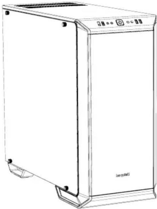
| Case type | Mid Tower |
| Dimensions (L x H x D) | 241 x 519 x 544 mm |
| Materials | SECC steel 0.7-0.8 mm, aluminum 0.8-1.2 mm, ABS plastic, tempered glass 4 mm |
| Supported motherboard form factor | E-ATX (30.5 x 27.5 cm), ATX, M-ATX, Mini-ITX |
| Front panel connectors | 2x USB 3.0, 1x USB 3.1 Type C, HD Audio (mic + headphone), RGB controller, 4-level fan controller |
| Integrated fan controller | 6x PWM 4-pin, PWM hub with Silent/Performance switch |
| Max CPU cooler height | 130 mm |
| Max GPU length | 286 mm (with HDD cage) / 430 mm (without cage) |
| Max PSU length | 150-285 mm |
| Storage bays | 7x 3.5" (including 1 in the compartment), 3x 2.5" (plus 6 additional) |
| Included fans | 2x SilentWings® 3 140mm (1600 RPM) - front and rear |
| Additional fan mounts | Front: 2x 140/120, Top: 3x 140/120, PSU shroud: 1x 140/120, Rear: 1x 140/120 |
| Radiator support | Front: 120/140/240/280/360 mm, Top: 120/240/360 mm, Rear: 120/140 mm |
| LED lighting | Front multi-color LED (white, red, green, blue, orange, purple) with manual control or motherboard sync |
| PCI slots | 7 + 2 (vertical) |
| Manufacturer warranty | 3 years (upon presentation of purchase invoice) |
| Weight | Approximately 14 kg (estimated) |
| Recommended PSU | ATX, max length 285 mm |
| Dust filters | Front (removable) and bottom |
Frequently Asked Questions - Dark Base 700 Be Quiet!
User questions about Dark Base 700 Be Quiet!
0 question about this device. Answer the ones you know or ask your own.
Ask a new question about this device
Download the instructions for your Desktop Computer in PDF format for free! Find your manual Dark Base 700 - Be Quiet! and take your electronic device back in hand. On this page are published all the documents necessary for the use of your device. Dark Base 700 by Be Quiet!.
USER MANUAL Dark Base 700 Be Quiet!
text_image
be quiet! be quiet!DARK BASE 700
OUTSTANDING FLEXIBILITY AND SILENCE
USER MANUAL
1. INTRODUCTION 4
- SPECIFICATIONS 5
- CONTENTS 6
- EXPLODED VIEW & DESCRIPTION OF PARTS 7
- FAN COMPATIBILITY 46
- RADIATOR SUPPORT 46
- REMOVAL OF THE SIDE PANELS 47
- INSTALLATION AND REMOVAL OF DRIVES AND FILTERS 48
- INVERTED LAYOUT 52
- INSTALLATION OF COMPONENTS 56
LIMITED WARRANTY 59
We are delighted you have chosen to buy our Dark Base PC case. Please read the information here and carefully follow all the instructions prior to installation. Should you have further questions, please contact our customer service. See contact information in the manufacturer's details section.
Warranty
- 3-year manufacturer's warranty for the consumer (original purchase from authorized be quiet! dealers only)
- Your original receipt of purchase will be required before warranty services are rendered. Please store it carefully.
- Manipulations and/or technical modifications of any kind, or damage due to the application of mechanical force, will void your warranty.
- To read the warranty terms and conditions in full, see Service/Warranty Conditions on our website at bequiet.com.
Our General Terms and Conditions of Business also apply. For details please refer online under bequiet.com.
Manufacturer's details
Listan GmbH & Co. KG | Biedenkamp 3a | 21509 Glinde | Germany
For support in Germany, you can call our free service hotline
Monday through Friday 09:00 - 17:30 (UTC+1)
Tel. 0049 40 736 7686 - 44 Fax 0049 40-7367686-69
Email: service@bequiet.com
Internet page: www.bequiet.com
Copyright
- You are not allowed to reproduce, disclose, publish or store the contents of this documentation, or excerpts of it, without the prior written consent of Listan.
- be quiet! is a registered trademark of Listan GmbH & Co. KG. Other products and company names mentioned in this documentation may be the brands or trademarks of their respective owners.
- In accordance with company policy, all Listan products are subject to ongoing development. Listan reserves the right to make changes and improvements to any product described in this documentation without prior notice.
- Under no circumstances shall Listan be held liable for loss of data or income, or for any specific, incidental, direct, or indirect damage, however it arises.
- The content of this documentation represents the status at time of writing. Listan does not assume, whether expressed or implicit, any liability for the correctness or completeness of the content of this documentation, including, but not limited to the implicit guarantee of market suitability for a particular purpose, unless applicable laws or jurisdiction specifically stipulate such a liability.
Listan reserves the right to make changes to this documentation or to withdraw the documentation at any time without prior announcement.
2. SPECIFICATIONS
natural_image
Line drawing of a stainless steel kitchen appliance with front panel and side legs (no text or symbols)| Dimensions (W x H x D in mm) 24 | x 519 x 544 |
| Case Type Midi Tower | |
| Material 0.7 - 0.8mm SECC steel, | 0.8 - 1.2mm aluminum, ABS plastic,4mm tempered glass |
| Motherboard Support E-ATX (30.5 x 27.5cm), ATX, M-ATX, Mini-ITX | |
| Front I/O 2x USB 3.0, 1x USB 3.1 Type C, HD audio (mic + headphone jacks),RGB control switch, 4-step fan controller | |
| Fan Speed Controller 6x 4-pin, Step Controller, PWM hub | |
| Max. Cooler Height (mm) 180 | |
| Max. Graphics Card Length (mm) 286 / 430 (w/o HDD cage) | |
| PSU Length (mm) 150 - 285 | |
| PCI Slots | 7 + 2 |
| 3.5" Bay | 7 |
| 2.5" Bay | 3 + 6 |
| Cooling Fans (mm) / (rpm) | Front: 1x SilentWings® 3 140mm / 1,600Rear: 1x SilentWings® 3 140mm / 1,600 |
| Optional Cooling Fans | Front: 2x 140/120Top: 3x 140/120PSU shroud: 1x 140/120Bottom: 1x 140/120 |
| Radiator Support (mm) | Front: 120, 140, 240, 280, 360Top: 120, 240, 360Rear: 120, 140 |
| Additional Features | Switchable multi mode, multi color RGB LED lighting at the front panel(white, red, green, blue, orange, purple), support of motherboard LEDcontrol |
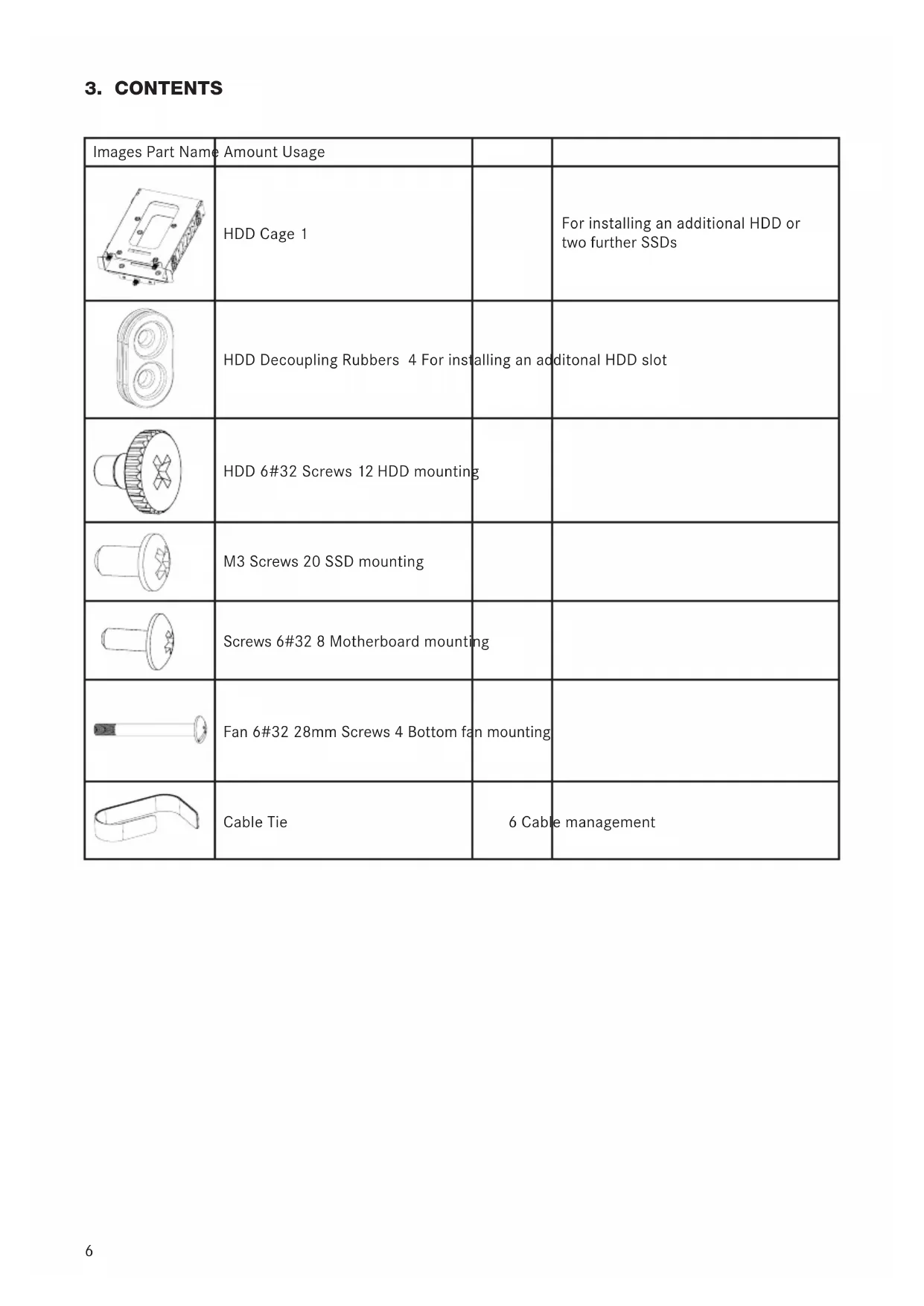
3. CONTENTS
| Images Part Name | Amount Usage | ||
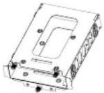 | HDD Cage 1 | For installing an additional HDD or two further SSDs | |
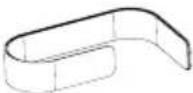
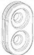 | HDD Decoupling Rubbers 4 For installing an additional HDD slot | ||
 | HDD 6#32 Screws 12 HDD mounting | ||
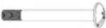
 | M3 Screws 20 SSD mounting | ||
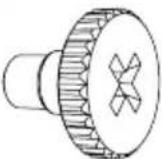
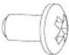
 | Screws 6#32 8 Motherboard mounting | ||
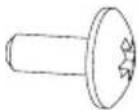
 | Fan 6#32 28mm Screws 4 Bottom fan mounting | ||
 | Cable Tie | 6 Cable management | |
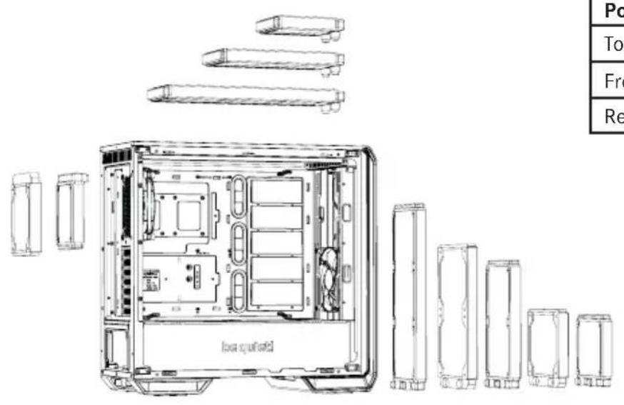
4. EXPLODED VIEW & DESCRIPTION OF PARTS
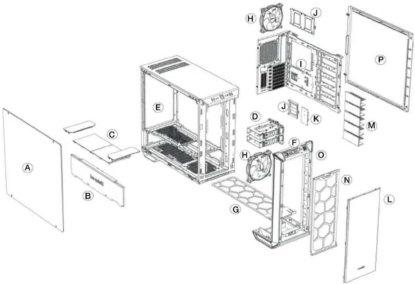
text_image
Exploded view diagram of a desktop computer system with labeled components from A to L| A Tempered Glass Window I Motherboard Tray | ||
| B Front Cover PSU Shroud J SSD Tray | ||
| C Top Cover PSU Shroud K Fan and LED Controller PCB | ||
| D HDD Slots L External Front Cover | ||
| E Chassis Body M HDD Slot Cover | ||
| F Front IO Panel N Front Air Filter | ||
| G Base Air Filter O Front Panel | ||
| H SilentWings ^® 3 Fan | P Side Panel | |
4.1 FRONT I/O AND MEDIA PORTS
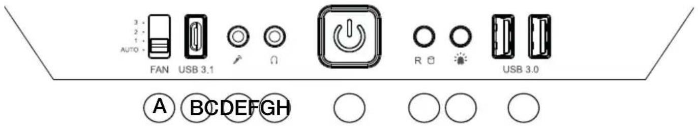
text_image
AUTO FAN USB 3.1 USB 3.0 A BCDEFGH ○ ○ ○ ○| A Fan Controller Switch E Power Button | ||
| B USB 3.1 Type C F HDD LED / Reset | ||
| C Microphone G LED Switch | ||
| D Headphone H USB 3.0 |
4.2 I/O PORTS
The Front I/O ports provided require connections to your motherboard. Refer to your motherboard handbook for information on pin assignments and sockets.
HD audio (headphone jack/microphone jack)
Find the HD audio pin connectors on your motherboard and attach the HD audio cables to the designated sockets.
USB 3.1 Type C
Find the USB 3.1 Type C pin connectors and attach the USB 3.1 Type C cables to the designated sockets.
USB 3.0
Find the USB 3.0 pin connectors on your motherboard and attach the USB 3.0 cables to the designated sockets.
On/Off Switch, Power On LED, Disk Operating LED, Reset Button
The plugs illustrated connect the On/Off Switch and LED lamps of the case to your motherboard. Take care you observe the correct polarity with the LEDs.
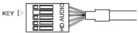
text_image
KEY HD AUDIO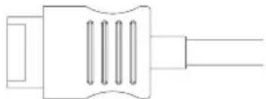
natural_image
Pure electrical connector diagram without any text, numbers, or symbols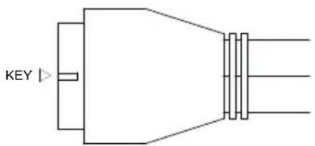
text_image
KEY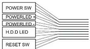
flowchart
graph TD
    A["POWER SW"] --> B["POWERLED +"]
    A --> C["POWERLED -"]
    A --> D["H.D.D LED"]
    A --> E["RESET SW"]
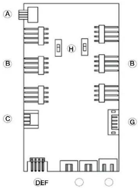
4.3 PCB PANEL / PORTS
text_image
A B C H G DEF| A 4-Pin PWM connector to motherboard |
| B 4-Pin PWM connector to fan |
| C LED connector to motherboard |
| D LED outlet for additional external LEDs |
| E Connecting plug for the front LEDs |
| F SATA power connection |
| G Ports for fan controller switch connector and LED switch on front I/O panel |
| H Switch for choosing between Silence and Performance Mode |
Please note: To ensure proper functioning of the fan control and the LED lighting, make sure that cable F is connected to the power supply.
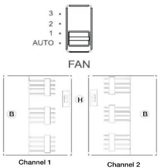
4.4 FAN CONTROLLER
text_image
3 2 1 AUTO FAN B H Channel 1 B Channel 2The fan controller has two modes of operation.
1. Automatic operation
In this mode the PWM signal of the motherboard is used and the speeds of all PWM fans connected can be adjusted automatically by the motherboard. The fan speed slider control must be set to its initial position of "AUTO" in this case.
In order to use the automatic PWM control of the fans it is necessary to connect the cable "A" of the PCB panel (4.3) with the PWM connector of your motherboard. Lacking such a connection it is only possible to manually control the speeds of fans connected.
2. Manual control
When the fan speed slider control is moved up from its initial position of "AUTO" the PWM signal is ignored and the fan speed can be manually set to one of three constant speeds.
In total it is possible to connect six PWM fans to the fan controller PCB. These six connections are subdivided into two channels (right and left) each with three connections. By operation of switch "H" on the PCB these channels can be switched independently from one another between "Silence" and "Performance" modes. The rate factors of the PWM fans connected here are determined as set out below according to the setting of the front I/O fan switch.
| Performance ModeIn combination with the Front I/O switch50% | 800rpm* (Position 1)70% | 1,120rpm* (Position 2)100% | 1,600rpm* (Position 3) | Silence ModeIn combination with the Front I/O switch25% | 400rpm* (Position 1)45% | 640rpm* (Position 2)65% | 1,040rpm* (Position 3) |
*with SilentWings® 3 1,600rpm
When the slider control is returned to its initial position of "AUTO" the PWM signal of the motherboard resumes control of the fans.
4.5 HANDLING OF THE LED ILLUMINATION
The LED illumination preinstalled in the front can be configured in several colors and operating modes. Further strips of LED illumination for lighting the case interior can be plugged into socket "D" on LED controller PCB (4.3) with a maximum combined rating of 24 watts.
WARNING! Only 12V LEDs may be connected.
To switch between synchronized operation and manual control mode keep switch "G" pressed for about three seconds.
Synchronized operation
It is possible to connect cable “C” of the PCB (4.3) and the corresponding RGB LED controller socket of your motherboard. The integrated illumination can then be controlled by the motherboard.
For information on operation of the LED controller of your motherboard refer to your motherboard handbook.
In manual mode you can cycle through the available colors (white, red, green, blue, orange, purple) by briefly pressing switch "G". An intermediate stage between each color enables "breath mode" for the previously selected color.
The individual switch stages are:
| 1 White 8 Blue breath | ||
| 2 White breath 9 Orange | ||
| 3 Red 10 Orange breath | ||
| 4 Red breath 11 Purple | ||
| 5 Green 12 Purple breath | ||
| 6 Green breath 13 Breath mode alternately in all colors | ||
| 7 Blue 14 LEDs off |
1. EINLEITUNG
natural_image
Line drawing of a modern stainless steel kitchen appliance with front panel and control buttons (no text or symbols)text_image
Exploded view diagram of a desktop computer system with labeled components from A to Lnatural_image
Line drawing of a stainless steel kitchen appliance with front panel and side legs (no text or symbols)text_image
Exploded view diagram of a desktop computer system with labeled components from A to Lnatural_image
Line drawing of a stainless steel waste bin with control panel and door indicators (no text or symbols)text_image
Exploded view diagram of a desktop computer system with labeled components from A to Ltext_image
3 2 1 AUTO FAN B H Channel 1 Channel 2natural_image
Line drawing of a white rectangular electronic device with control panel and indicator lights (no text or symbols)text_image
Exploded view diagram of a desktop computer system with labeled components from A to Ltext_image
3 2 1 AUTO FAN B H Channel 1 Channel 2natural_image
Line drawing of a rectangular stainless steel kitchen appliance with control panel and buttons (no text or symbols)text_image
Exploded view diagram of a desktop computer system with labeled components from A to Lnatural_image
Pure electrical circuit lines without any symbols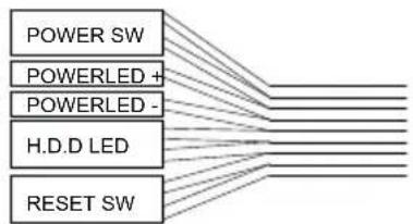
flowchart
graph TD
    A["POWER SW"] --> B["POWERLED +"]
    A --> C["POWERLED -"]
    A --> D["H.D.D LED"]
    A --> E["RESET SW"]
natural_image
Technical line drawing of a server rack with internal components and external connectors (no text or symbols)| Position Fan Size (mm) |
| Top 3x 120, 3x 140 |
| Bottom 1x 120, 1x 140 |
| Front 3x 120, 3x 140 |
| Rear 1x 120, 1x 140 |
| PSU Shroud 1x 120, 1x 140 |
6. EN RADIATOR SUPPORT | DE RADIATOREINBAU | FR SUPPORT RADIATEURS PL KOMPATYBILNOŚĆ Z RADIATORAMI | ES SOPORTE PARA RADIADOR RU ПОДДЕРЖКА РАДИАТОРОВ
text_image
Box shield Po Top Fro Re| Position Radiator Size (mm) | |
| Top 120, 240, 360 | |
| Front | 120, 140, 240, 280, 360 |
| Rear | 120, 140 |
7. EN REMOVAL OF THE SIDE PANELS | DE ENTFERNEN DER SEITENTEILE FR DÉMONTAGE DES PANNEAUX LATÉRAUX | PL DEMONTAZ PANELU BOCZNEGO | ES DESMONTAJE DE LOS PANELES LATERALES | RU DEMONTаж БОКОВЫХ ПАНЕЛЕЙ
natural_image
Technical line drawing of a computer tower case with visible internal components and labeled parts (no text or symbols present)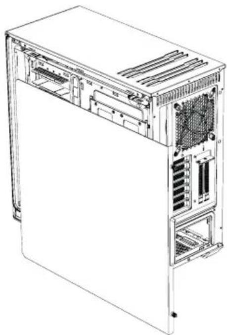
natural_image
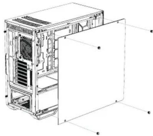
Technical line drawing of a computer tower case with visible internal components and ventilation slots (no text or labels)EN To remove the glass side panel, unscrew the four fixing screws as shown
DE Zum Entfernen des Glasseitenteils lösen Sie bitte die vier gekennzeichneten Befestigungsschrauben
FR Pour retirer le panneau latéral en verre, dévissez les quatre vis de fixation comme indiqué
PL Aby zdemontować szklany panel boczny, odkręć cztery śruby mocujące, jak pokazano na rysunku
ES Para quitar el panel lateral de cristal, desenrosque los cuatro tornillos de fijación muestra
RU Для демонтажа боковой стеклянной панели открытите четыре крепежных винта, как показано на рисунке
EN To remove the steel side panel, unscrew the two screws as shown and draw the side panel towards the rear with the grip provided for its purpose
DE Zum Entfernen des Stahlseitenteils lösen Sie bitte die zwei gekennzeichneten Schrauben und ziehen das Seitenteil an dem hierfür vorgesehenen Eingriff nach hinten
FR Pour retirer le panneau latéral en acier, dévissez les deux vis comme indiqué et faites glisser le panneau latéral vers l'arrière grâce à la poignée prévue à cet effet
PL Aby zdemontować stalowy panel boczny, odkręć dwie śruby, jak pokazano na rysunku i panel boczny do tyłu za pomocą uchwytu do tego przewidzianego
ES Para quitar el panel lateral de acero, desenrosque los dos tornillos tal como se muestra y extraiga el panel lateral hacia la parte trasera con el saliente disponible para ello
RU Для демонтажа стальной боковой панели открытите два винта, как показано на рисунке, и сдвиньте боковую панель назад
pocia.
- EN INSTALLATION AND REMOVAL OF DRIVES AND FILTERS | DE ANBRINGEN UND ENTFERNEN VON LAUFWERKEN UND FILTERN | FR MONTAGE ET DÉMONTAGE DES DISQUES ET DES FILTRES | PL INSTALACJA I DEMONTAZ NAPEDÓW I FILTRÓW | ES INSTALACIÓN Y DESMONTE DE DISCOS Y FILTROS RU УСТАНОВКА И ДЕМОНТАЖ ПРИВОДОВ И ФИЛЬТРОВ
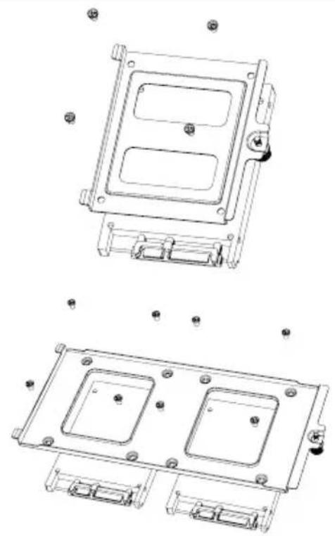
8.1 INSTALLATION OF HDDs AND SSDs WITHIN THE 3.5" DRIVE SLOT / INSTALLATION VON HDDs UND SSDs INNERHALB DES 3.5" LAUFWERK-SLOTS / INSTALLATION D'UN PERIPHERIQUE 3,5" (DISQUE DUR) / INSTALACJA HDD I SSD W GNIEZDZIE 3.5" / INSTALACIÓN DE DISCOS DUROS Y SDD EN LA RANURA PARA UNIDADES DE 3,5" / УСТАНОВКА HDD И SSD ВНУТРИ 3.5" СЛОТОВ
 | EN Install an HDD into the 3.5" slot using the four screwsDE Installieren Sie die HDDs mit den vier Schrauben im 3.5" SlotFR Installez un disque dur avec 4 vis dans l'emplacement 3,5"PL Zainstaluj dysk twardy w gnieździe pomocą czterech śrubES Puede instalar un disco duro en la ranura de 3,5" usando los cuatro tornillosRU Установите HDD внутрь слота 3.5" используя четыре винта |
 | EN It is possible to install two SSDs (top and bottom) into each HDD slotDE Es können zwei SSDs (Ober- und Unterseite) pro HDD-Slot installiert werdenFR Il est possible d'installer deux SSD (dessus et dessous) dans chaque emplacement pour disque dur.PL Możliwe jest zainstalowanie dwóch dysków SSD (góra i dół) do każdego gniazda HDD.ES También se pueden instalar dos SDD (uno arriba y otro abajo) en cada ranura para discos durosRU В каждый слот HDD может быть установлено до двух SSD (вверху и внизу) |
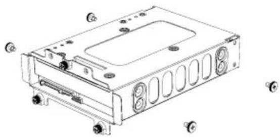
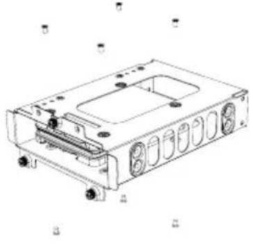
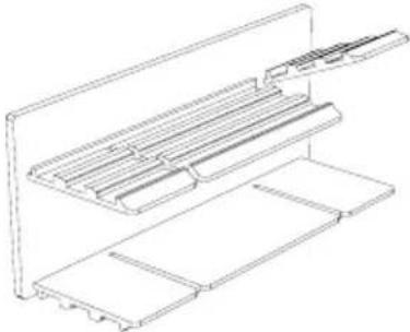
8.2 INSTALLATION OF SSDs ON THE BRACKET BEHIND THE MOTHERBOARD TRAY / INSTALLATION VON SSDs AUF DEN HALTERUNGEN HINTER DEM MB-TRAY / INSTALLATION DES SSD SUR LE SUPPORT À L'INTÉRIEUR DU PLATEAU DE LA CARTE MERE / INSTALACJA SSD NA WSPORNIKU Z TYŁU TACKI PŁYTY GŁÓWNEJ / INSTALACIÓN DE DISCOS SDD EN EL SOPORTE DETRÁS DE LA BANDEJA DE LA PLACA BASE / УСТАНОВКА SSD НА КРОНШТЕЙН ПОЗАДИ ПОДДОНА МАТЕРИНСКОЙ ПЛАТЫ
 | EN Remove the SSD tray by unscrewing the fix screwsDE Entfernen Sie die SSD-Trays durch Lösen der BefestigungsschraubeFR Retirez le support SSD en dévissant les vis de fixationPL Wyjmij tackę SSD, odkręcając śruby mocująceES Extraiga la bandeja SSD desenroscando los tornillos de fijaciónRU Открутите крепежные винты и снимите кронштейн SSD. |
natural_image
Technical line drawing of a mechanical housing assembly with mounting holes and internal compartments (no text or symbols)EN Affix the SSD and refit the bracket into the case
DE Befestigen Sie die SSD und setzen Sie den Halter wieder ins Gehäuse ein
FR Fixez le SSD et remettez le support dans le boîtier
PL Zamontuj SSD i zamocuj wspornik z powrotem do obudowy
ES Coloque el SSD y vuelva a poner el soporte en la carcasa
RU Закрепите SSD и установите кронштейн в корпус
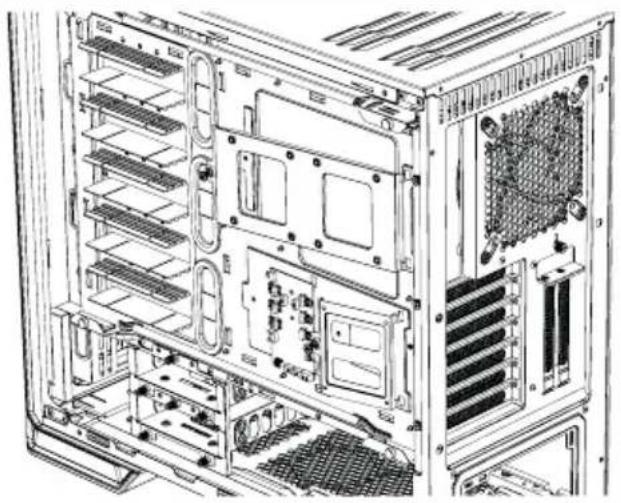
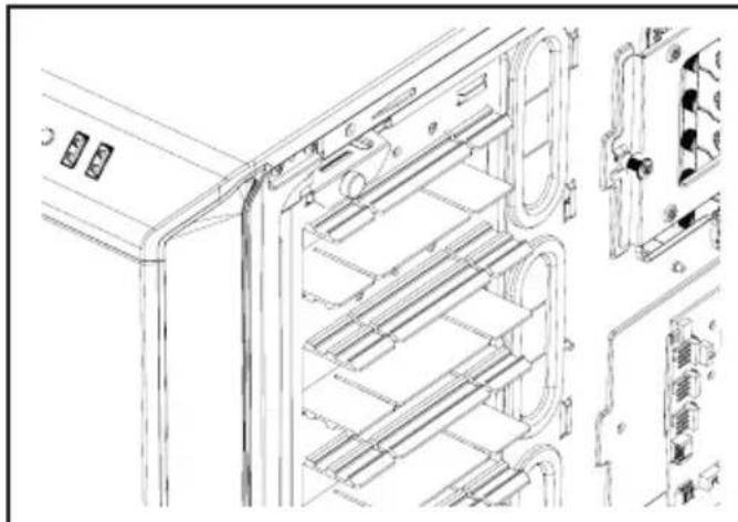
8.3 HDD-SLOT COVERS / HDD-SLOT-COVER / COUVERCLE DE CACHE POUR DISQUE DUR (HDD) / ZAŚLEPKI SLOTÓW HDD / CUBIERTAS DE LAS RANURAS PARA DISCOS DUROS / ЗАГЛУШКИ СЛОТОВ HDD
natural_image
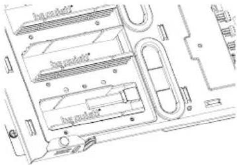
Technical line drawing of a server rack with internal components and mounting points (no text or symbols)EN The five HDD slot covers supplied mounted in three steps to fully cover the holes or keep them partly open
DE Die fünf mitgelieferten HDD-Slot-Cover können in drei Stufen verstellt werden. Sie verdecken die Öffnungen vollständig oder in zwei verschiedener Höhen für verschiedene Kabeldicken
FR Les cinq couvercles des cages HDD fournis peuvent être montés en trois étapes pour couvrir complètement les orifices ou les garder entrouverts
PL Pięć zaślepek HDD znajduje się w zestaw
Można je zamontować trzystopniowo, aby w pełni
zasłonić otwory lub pozostawić je częściowo of
warte
ES Las cinco cubiertas para las ranuras de los discos duros suministradas se pueden montar en tres pasos para cubrir por completo los orificios o bien se pueden dejar parcialmente abiertos
RU Пять заглушек слотов HDD могут быть установлены в трех положениях: полностью закрывая отверстия или частично открывая их
  | EN According to requirements, they can be removed or repositioned to install VGA cards or for cable managementDE Je nach Anforderung können die Cover entfernt werden oder zum Einsetzen von VGA-Karten oder für die Kabelorganisation justiert werdenFR Selon les besoins, ils peuvent être supprimés ou repositionnés pour installer des cartes VGA ou pour la gestion des câblesPL Zgodnie z potrzebami mogą zostać usunięte lub przeniesione w inne miejsce w celu zainstalowania kart VGA lub zarządzania przewodamiES En función de los requisitos, se pueden quitar o volver a colocar para instalar tarjetas VGA o para modificar el cableadoRU Для установки VGA карт и монтажа кабелей заглушки могут быть сняты или переставлены |
   | EN To optimize the cable routing up to two individual segments of the covers can be „punch necessary. Warning: Punched out segments cannot be refittedDE Zur Optimierung der Kabelführung können einzelne Segmente der jeweiligen Abdeckung “herausgebrochen” werden. Warnung: Einmal herausgebrochene Segmente können nicht wieder angebracht werdenFR Pour optimiser le routage des câbles segments individuels, les couvercles peuvent être “perforés” si nécessaire. Attention: les segments perforés ne peuvent pas être remis en place.PL W celu optymalizacji prowadzenia przewodów w razie potrzeby można wyłamać dwa fi zaślepki. Ostrzeżenie: wyłamanych fragment zaślepki nie da się z powrotem zamocować.ES Para optimizar el cableado, se pueden quitar hasta dos segmentos individuales de las cubiertas, si es necesario. Advertencia: Los segmentos retirados no se pueden volver a montar.RU Для упрощения монтажа кабелей могут быть удалены до двух отдельных сегментов заглушек. Внимание: Удаленные сегменты не могут восстановлены. |
8.4 AIR FILTER REMOVAL / ENTFERNEN DER LUFTFILTER / DÉMONTAGE DES FILTRES A POUSSIÈRE / DEMONTAŻ FILTRÓW POWIETRZA / DESMONTAJE DEL FILTRO DE AIRE / СНЯТИЕ ВОЗДУШНОГО ФИЛЬТРА
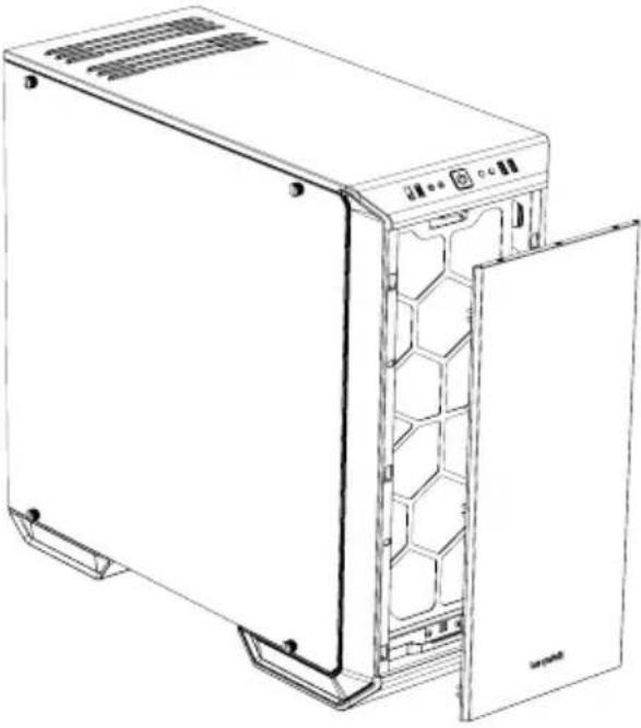 | ENTo remove or clean the air filter the front panel of the case must first be detached. T grasp behind the front edge of the panel from the front and pull it off towards youDEZum Entfernen und Reinigen der Luftfilter muss zunächst die Frontblende des Gehäuses entfernt werden. Hierzu greifen Sie von vorne hinter die Vorderkante und ziehen die Blende zu sich hin abFRPour retirer ou nettoyer le filtre à air, neau avant du boîtier doit d'abord être Pour ce faire, saisissez par l'arrière le bord avant du panneau frontal et tirez-le vers vousPLW celu usunięcia lub oczyszczenia filtra powietrza, najpierw należy zdjąć panel przeddowy. W tym celu chwyć za przednią krawędź panelu od przodu i pociągnij do siebieESPara desmontar o limpiar el filtro de aire hay que quitar antes el panel frontal.Para ello, introduzca los dedos tras el borde frontal del panel por delante y tire para soltarloRUДля очистки воздушных фильтров необходимо предварительно снять фронтальную панель корпуса. Для этого возьмитесь за передний край панели и потяните ее на себя |
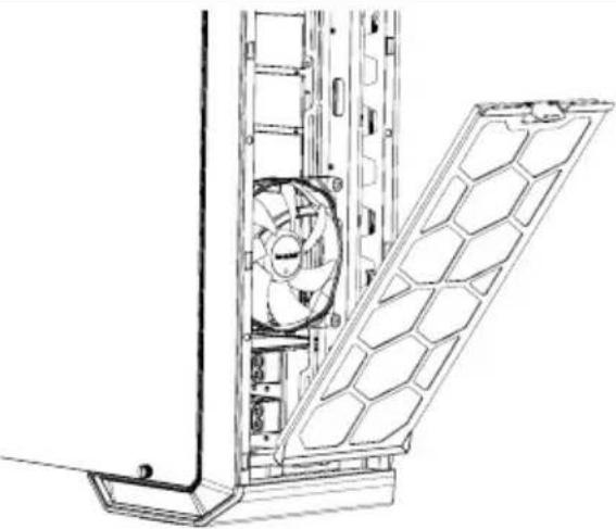 | ENBy depressing the hooks on top, unlatch and remove the front filters as shownDEDurch Drücken auf den oberen Haken entriegeln Sie den FilterFREn appuyant sur les crochets du dessus, déverrouillez et enlevez les filtres avant comme illustréPLWciśnij haczyki na górze, odblokuj i usuń przednie filtry zgodnie z rysunkiemESPresione las pestañas de la parte superior, desenganche los filtros frontales y retírelos tal como se muestraRUНажмите на верхний фиксатор и с фильтр, как показано на рисунке |
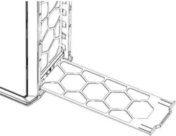 | ENSlide out the bottom filter to the frontDEZiehen Sie den unteren Luftfilter na herausFRFaites glisser le filtre du dessous vers l'avantPLWysuń filtr dolny do przoduESDeslice el filtro inferior hacia la parte frontalRUВытащите нижний фильтр вперед |
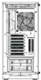
9. EN INVERTED LAYOUT | DE INVERTIERTES LAYOUT | FR CHANGEMENT DE CONFIGURATION | PL UKŁAD ODWRÓCONY | ES CONFIGURACIÓN INVERTIDA RU ОБРАТНОЕ РАСПОЛОЖЕНИЕ
Default layout of the Dark Base 700 Inverted layout of the Dark Base 700
natural_image
Back view of a computer tower rack with internal components and ventilation slots (no visible text or labels)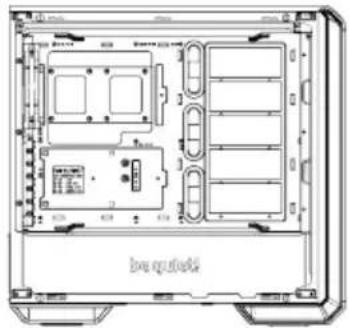
natural_image
Technical line drawing of an electronic device chassis with internal compartments and ports (no text or symbols)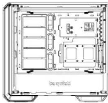
natural_image
Technical line drawing of a computer chassis showing internal compartments and storage areas (no text or symbols)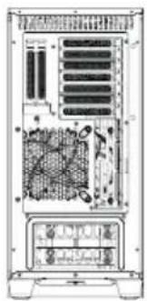
natural_image
Back view of a computer tower internal structure showing drive bays and ventilation slots (no text or labels visible)natural_image
Line drawing of a desktop computer tower showing internal components including CPU socket, fan, and drive unit (no text or symbols)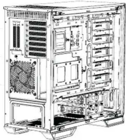
natural_image
Technical line drawing of a computer tower case showing internal components like drive bays and expansion slots (no text or labels)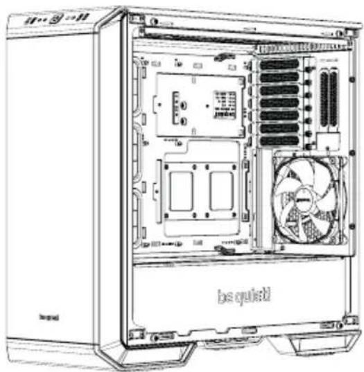
natural_image
Line drawing of a desktop computer tower showing internal components like CPU socket and fan (no text or symbols)EN Put back the radiator/fan bracket and secure this again with its two screws. Refit the PSU front panel
EN Remove the four screws (including the decoupling rubber) used to mount the glass side panel
EN Refit the screws (including the decoupling rubber) to remount the glass side panel on the opposite side
text_image
box substrateEN Attach the motherboard with the M3 screws supplied. Standoffs are preinstalled for installation of an ATX motherboard
DE Befestigen Sie das Mainboard mit den mitgelieferten M3 Schrauben. Die Standoffs sind für die Installation von ATX Mainboards bereits vorinstalliert
FR Fixez la carte mère avec les vis Les entretoises sont préinstallés pour l'installation d'une carte mère ATX
PL Zamocuj płytę główną z pomocą dostarczonych śrub M3. Standoffy są fabrycznie zainstalowane w celu zainstalowania płyty głównej ATX
ES Fije la placa base con los tornillos M3 suministrados.Hay separadores premontados para la instalación en una placa base ATX
RU Закрепите материнскую плату комплект винтами М3. Втулки изначально установлены плат АТХ формата
Test Bench / Test Bench / Table de bench / Test Bench / Banco de pruebas / Тестовый стенд
natural_image
Technical line drawing of a computer tower internal structure with fan and drive components (no text or labels)EN If required, the motherboard tray can be removed (see instructions for this under 9.) and used as a test bench
DE Das Mainboard-Tray kann bei Bedarf gemäß Anleitung (9.) entnommen und als Test-Bench verwendet werden
FR Si nécessaire, le plateau de la carte mère peut être retiré (voir les instructions pour ce faire au point 9.) et utilisé comme table de bench
PL W razie potrzeby, można usunąć ta głównej (patrz instrukcje w punkcie 9.) i używać jej jako stanowiska testowego
ES Si es necesario, la bandeja de la placa base (véanse las instrucciones para ello en la sección 9) se puede retirar y utilizar como banco de pruebas
RU При необходимости поддон материнской платы может быть извлечен (см. пункт 9 инстру использован в качестве тестового стенда
PCI
text_image
be qued begaEN Before you start to install a PCI / PCI-E add-on-card, first remove the PCI slot cover
DE Entfernen Sie die PCI-Slot-Abdeckungen bevor Sie mit der Installation einer PCI/PCI-E Add-on-Card beginnen
FR Avant de commencer à installer une carte PCI / PCI-E, retirez d'abord le cache de l'emplacement PCI
PL Przed przystąpieniem do instalowania kowej karty PCI / PCI-E, najpierw zdejmij pokrywę gniazda PCI
ES Para poder instalar una tarjeta adicional PCI/PCI-E se debe retirar antes la cubierta de la ranura PCI
RU Перед установкой
демонтируйте слоты PCI
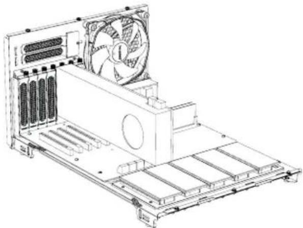
VGA
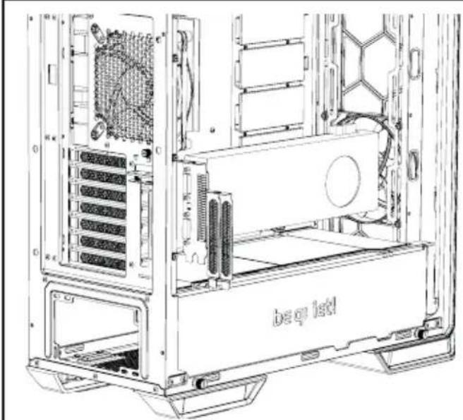
natural_image
Technical line drawing of a computer tower case showing internal components like CPU, drive bega, and tower panel (no text or symbols)EN VGA cards can also be installed vertically. The "Raiser Card" that is needed to achieve this is not included in the scope of delivery
DE VGA-Karten können vertikal installiert werden. Die hierfür notwendige „Raiser Card“ ist Lieferumfang enthalten
FR Les cartes VGA peuvent également être installées verticalement. La «Carte Riser» nécessaire pour y parvenir n'est pas incluse
PL Karty VGA można także instalować "Raiser Card", umożliwiający taki montaż nie znajduje się w zestawie
ES Las tarjetas VGA también se pueden instalar verticalmente. La tarjeta necesaria no se incluye en los elementos suministrados
RU Поддерживается вертикальная установка видеокарт. Необходимый для этого переходник "Riser card" в комплект поставки не входит
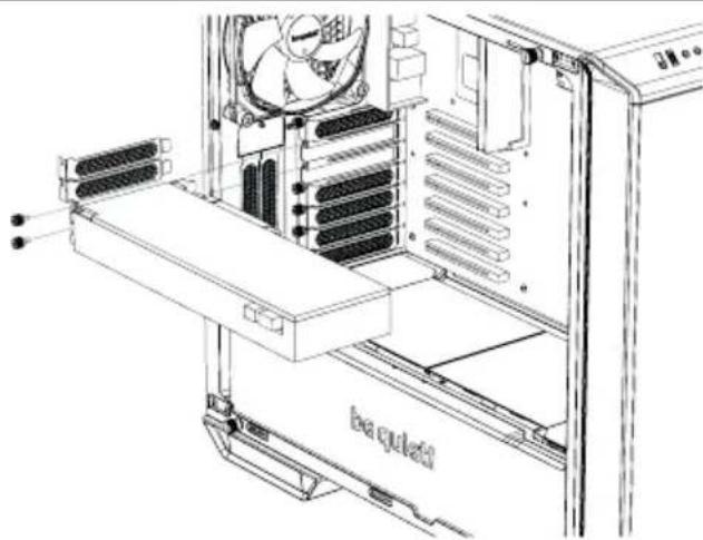
PSU / Netzteil / Alimentation / Zasilacz / Fuente de alimentación / Блок питания
text_image
Technical diagram of a computer tower case with labeled components and internal structureEN Place the PSU into the housing and secure it with the screws supplied by the PSU manufacturer
DE Platzieren Sie das Netzteil im Gehäuse und sichern es mit den hierfür vom Hersteller vorgesehenen Schrauben
FR Placez l'alimentation dans l'emplacement et fixez-la avec les vis fournies par le fabricant l'alimentation
PL Umieść zasilacz w obudowie i przymocuj z pomocą śrub dostarczonych przez producenta zasi-lacza
ES Coloque la fuente de alimentación en la carcasa y asegúrela con los tornillos suministrados por el fabricante de la fuente de alimentación
RU Ус тан о в и те бло к пит а н и явко
его винтами, поставляемыми с блоком питания
oricant
ocuj
p пус
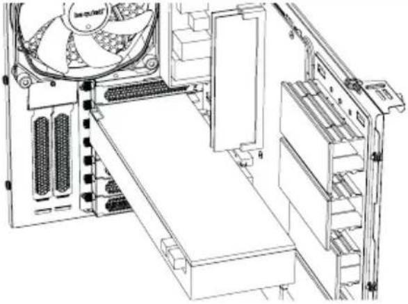
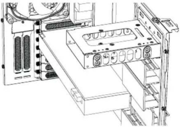
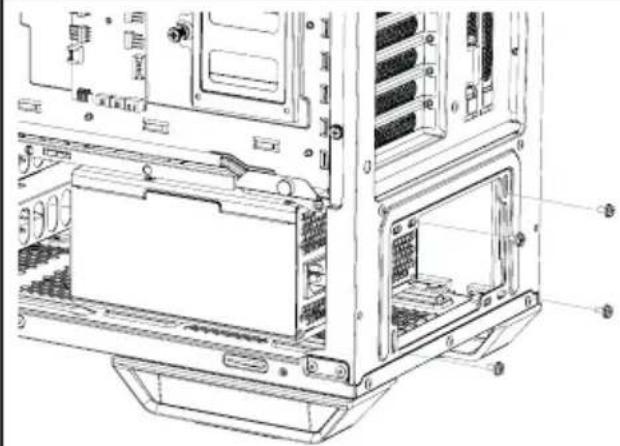
Top Radiator, Fans / Radiator, Lüfter oben / Radiateurs, ventilateurs supérieurs / Górny radiator, wentylator / Radiador, ventiladores superiores / Radiator, вентиляторы верхней панели
natural_image
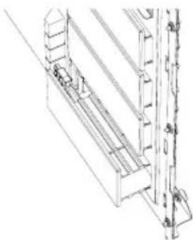
Technical line drawing of a server rack frame with internal components and mounting brackets (no text or symbols)EN Unscrew the two screws that secure the radiator/fan bracket and slide this out
DE Lösen Sie die zwei Schrauben der Radiator-Lüfterhalterung und ziehen Sie diese heraus
FR Dévissez les deux vis qui fixent le radiateur / ventilateur et faites-le glisser
PL Odkręcić dwie śruby mocujące wspornik chłodnicy / wentylatora i wysunąć
ES Desenrosque los dos tornillos que sujetan el soporte del radiador/ventilador y deslícelo para extraerlo
RU Открутите два винта и извлеките кронштейн радиатора/вентиляторов наружу
nicht
pionowc
support
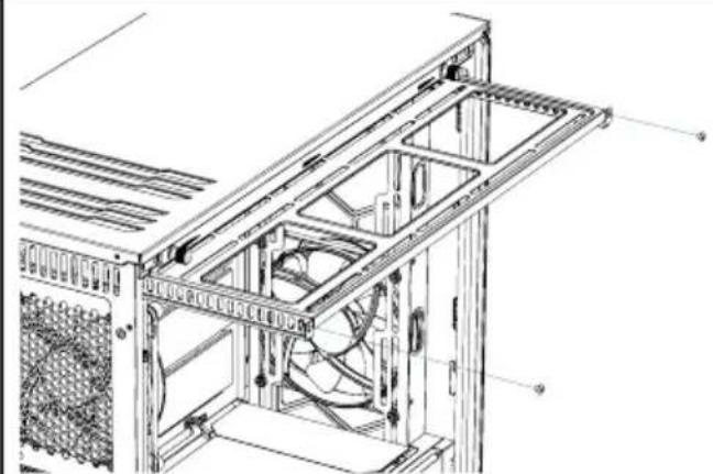
natural_image
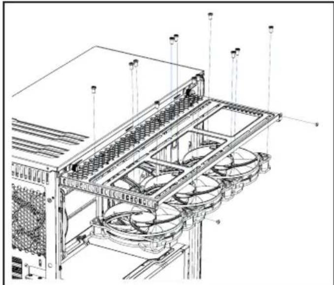
Technical line drawing of a server rack with multiple fans and ventilation grilles (no text or symbols)EN Fit your radiator or fans onto the mounting bracket and secure these with screws as illustrated
DE Platzieren Sie Ihren Radiator oder Lüfter auf der Halterung und verschrauben Sie diese gemäß Abbildung
FR Installez votre radiateur ou vos ventilateurs sur le support de montage et fixez-les avec des vis comme illustré
PL Zamontuj radiator lub wentylatory na wsporniku i zabezpiecz je śrubami, jak pokazano na ilustracji
ES Coloque el radiador o los ventiladores en el so-
porte de montaje y asegúrelos con tornillos tal como
se muestra
RU Установите радиатор или вентиляторы кронштейн и закрепите их винтами, как показано на рисунке
на
Limited Warranty
Per the terms and conditions of this limited warranty as given below, be quiet! warrants its new products to be free of defects resulting from faulty materials and faulty manufacturing for the length of the warranty period.
I. APPLICABILITY
This non-transferable warranty is applicable to newly purchased, previously unopened be quiet! products and is enforceable by only the original consumer purchaser. Proof of purchase is required for warranty service, so should be retained. be quiet! does not provide warranty registration services.
II. WARRANTY PERIOD
For eligible products, parts and labor are warranted for the applicable warranty period from the date of purchase. The applicable warranty period varies by product model, and is identified in your user documentation, on the product package, or as listed below. Should any of these warranty periods differ, the longest specified warranty period will apply. Replaced products will be warranted for the remainder of the original warranty period or thirty days, whichever is longer.
III. EXCLUSIONS
The following are not covered by the warranty:
- Normal wear and tear.
- Any product which has been modified without permission from be quiet!, or on which the serial number or warranty sticker has been defaced, modified, or removed.
- Damage, deterioration or malfunction resulting from:
Accident, abuse, misuse or improper use, neglect, connection to an improper voltage source, unauthorized product modification, or failure to follow instructions included with the product.
Fire, water, lightning, or other acts of nature.
Repair or attempted repair by anyone not authorized by be quiet!.
Shipping or transport damage (claims must be made with the carrier).
Any other cause which does not relate to a defect in materials or manufacturing workmanship.
-
Cartons, cases, batteries, cabinets, tapes, accessories or other consumables used with this product.
-
be quiet!, Inc. does not warrant that this product will meet your requirements. It is your responsibility to determine the suitability of this product for your purpose.
-
Removal or installation charges.
-
Shipping charges.
-
Any incidental charges.
IV. EXCLUSION OF DAMAGES
be quiet!'s sole obligation and liability under this warranty is limited to the repair or replacement of a defective product at its option. be quiet! shall not, in any event, be liable for any special, incidental, indirect, or consequential damages whatsoever, including but not limited to loss of profits, revenue, or data (whether direct or indirect), damages resulting from interruption of service and loss of business, or for liability in tort relating to this product or resulting from its use or possession, even if be quiet! has been advised previously of the possibility of such damages.
V. LIMITATIONS OF IMPLIED WARRANTIES
There are no other warranties, expressed or implied, including but not limited to those of merchantability or fitness for a particular purpose. The duration of implied warranties is limited to the warranty length specified in Paragraph II.
VI. LOCAL LAW AND YOUR WARRANTY
This warranty gives you specific legal rights. You may also have other rights granted under local law. These rights may vary.
VII. NO OTHER WARRANTY
No be quiet! employee, dealer, or other agent is authorized to make any modification, extension, or addition to this warranty.
VIII. TO OBTAIN TECHNICAL SUPPORT OR WARRANTY SERVICE
Please see your product owner's manual or visit the Online Support section at www.bequiet.com for details and contact information. You will need to provide proof of purchase for warranty service.