Flat Star LED PAR - Lighting Cameo - Free user manual and instructions
Find the device manual for free Flat Star LED PAR Cameo in PDF.

User questions about Flat Star LED PAR Cameo
0 question about this device. Answer the ones you know or ask your own.
Ask a new question about this device
Download the instructions for your Lighting in PDF format for free! Find your manual Flat Star LED PAR - Cameo and take your electronic device back in hand. On this page are published all the documents necessary for the use of your device. Flat Star LED PAR by Cameo.
USER MANUAL Flat Star LED PAR Cameo
We have designed this product to operate reliably over many years. Please read this User's Manual carefully, so that you can begin making optimum use of your Cameo Light product quickly. Learn more about Cameo Light on our website www.CAMEOLIGHT.COM.
PREVENTIVE MEASURES
- Please read these instructions carefully.
- Keep all information and instructions in a safe place.
- Follow the instructions.
- Observe all safety warnings. Never remove safety warnings or other information from the equipment.
- Use the equipment only in the intended manner and for the intended purpose.
- Use only sufficiently stable and compatible stands and/or mounts (for fixed installations). Make certain that wall mounts are properly installed and secured. Make certain that the equipment is installed securely and cannot fall down.
- During installation, observe the applicable safety regulations for your country.
- Never install and operate the equipment near radiators, heat registers, ovens or other sources of heat. Make certain that the equipment is always installed so that is cooled sufficiently and cannot overheat.
- Never place sources of ignition, e.g., burning candles, on the equipment.
- Ventilation slits must not be blocked.
- This appliance is designed exclusively for indoor use, do not use this equipment in the immediate vicinity of water (does not apply to special outdoor equipment - in this case, observe the special instructions noted below). Do not expose this equipment to flammable materials, fluids or gases.
- Make certain that dripping or splashed water cannot enter the equipment. Do not place containers filled with liquids, such as vases or drinking vessels, on the equipment.
- Make certain that objects cannot fall into the device.
- Use this equipment only with the accessories recommended and intended by the manufacturer.
- Do not open or modify this equipment.
- After connecting the equipment, check all cables in order to prevent damage or accidents, e.g., due to tripping hazards.
- During transport, make certain that the equipment cannot fall down and possibly cause property damage and personal injuries.
- If your equipment is no longer functioning properly, if fluids or objects have gotten inside the equipment or if it has been damaged in anot her way, switch it off immediately and unplug it from the mains outlet (if it is a powered device). This equipment may only be repaired by authorized, qualified personnel.
- Clean the equipment using a dry cloth.
- Comply with all applicable disposal laws in your country. During disposal of packaging, please separate plastic and paper/cardboard.
- Plastic bags must be kept out of reach of children.
FOR EQUIPMENT THAT Connects TO THE POWER MAINS:
- CAUTION: If the power cord of the device is equipped with an earthing contact, then it must be connected to an outlet with a protective ground. Never deactivate the protective ground of a power cord.
- If the equipment has been exposed to strong fluctuations in temperature (for example, after transport), do not switch it on immediately. Moisture and condensation could damage the equipment. Do not switch on the equipment until it has reached room temperature.
- Before connecting the equipment to the power outlet, first verify that the mains voltage and frequency match the values specified on the equipment. If the equipment has a voltage selection switch, connect the equipment to the power outlet only if the equipment values and the mains power values match. If the included power cord or power adapter does not fit in your wall outlet, contact your electrician.
- Do not step on the power cord. Make certain that the power cable does not become kinked, especially at the mains outlet and/or power adapter and the equipment connector.
- When connecting the equipment, make certain that the power cord or power adapter is always freely accessible. Always disconnect the equipment from the power supply if the equipment is not in use or if you want to clean the equipment. Always unplug the power cord and power adapter from the power outlet at the plug or adapter and not by pulling on the cord. Never touch the power cord and power adapter with wet hands.
- Whenever possible, avoid switching the equipment on and off in quick succession because otherwise this can shorten the useful life of the equipment.
- I t a
- To disconnect the equipment from the power mains completely, unplug the power cord or power adapter from the power outlet.
- If your device is equipped with a Volex power connector, the mating Volex equipment connector must be unlocked before it can be removed. However, this also means that the equipment can slide and fall down if the power cable is pulled, which can lead to personal injuries and/or other damage. For this reason, always be careful when laying cables.
- Unplug the power cord and power adapter from the power outlet if there is a risk of a lightning strike or before extended periods of disuse.
- The device must only be installed in a voltage-free condition (disconnect the mains plug from the mains).
- Dust and other debris inside the unit may cause damage. The unit should be regularly serviced or cleaned (no guarantee) depending on ambient conditions (dust etc., nicotine, fog) by qualified personnel to prevent overheating and malfunction.
- Please keep a distance of at least 0.5m to any combustible materials.
- Power cables to power multiple devices must have a cross-section of at least 1.5mm^2 . Within the EU, the cables must correspond to H05VV-F, or similar. Suitable cables are offered by Adam Hall. With these cables, you can connect multiple devices via the power OUT connection to the power IN connection of an additional device. Make sure that the total current consumption of all connected devices does not exceed the specified value on all connected devices (label on the device). Make sure to keep power cable connections as short as possible.
CAUTION: To reduce the risk of electric shock, do not remove cover (or back). There are no user serviceable parts inside. Maintenance and repairs should be exclusively carried out by qualified service personnel.
The warning triangle with lightning symbol indicates dangerous uninsulated voltage inside the unit, which may cause an electrical shock.

The warning triangle with exclamation mark indicates important operating and maintenance instructions.
The housing surface of the spotlight can heat up to temperatures as high as 70^ in regular use. Ensure that it is not possible to come into contact with the housing unintentionally. Always allow sufficient time for the lamp to cool down before dismantling, carrying out maintenance work or charging etc.

Warning! This device is designed for use below 2000 metres in altitude.

Warning! This product is not intended for use in tropical climates.
Caution! Intense LED light source! Risk of eye damage. Do not look into the light source.
INTRODUCTION
2-IN-1 LED EFFECT SPOTLIGHT
CLFLATSTAR
CONTROL FUNCTIONS:
3-channel 1, 3-channel 2, 7-channel, 12-channel and 13-channel DMX control
Separate control of the 6-in-1 LEDs and the SMD LED ring
Control via IR remote control
FEATURES:
DMX-512 control. Master/Slave operation. IR remote control included. Stand-alone programmes. Music control via built-in microphone. Adjustable mounting bracket included. Operating voltage 100-240V AC. Power consumption 60W
6-in-1 centre LEDs
3×12W RGBWA+UV LEDs
SMD LED ring
27× 0.5W RGB LEDs
OPERATION:
The Cameo CLFLATSTAR is an effects spotlight which combines 3 RGBWA+UV 6-in-1 LEDs and 27 SMD LEDs. The 2 effects can be controlled independently of one another. The Cameo effects spotlight can be used as a stand-alone unit, in master/slave operation, via music control, IR remote control and via DMX-512 protocol.
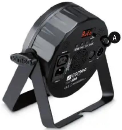
FRONT
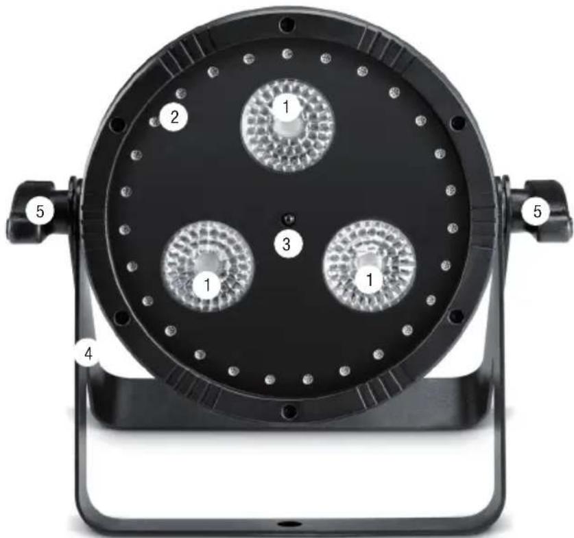
CENTRE LEDs
Three 6-in-1 RGBWA+UV LEDs with control via DMX.
SMD LED RING
Nine segments, each with three SMD RGB LEDs arranged in a ring. The segments are controlled separately via integrated auto-programmes (no separate control via DMX, not dimmable).
3 INFRARED INTERFACE
Controlling the effects spotlight with the supplied infrared remote control. Ensure that the infrared interface of the remote control is positioned within 8m of the effects spotlight, directly in -line with its infrared interface.
4 Stand or mounting bracket.
5 Wingnuts to secure the bracket.
CONNECTIONS, OPERATING AND DISPLAY ELEMENTS
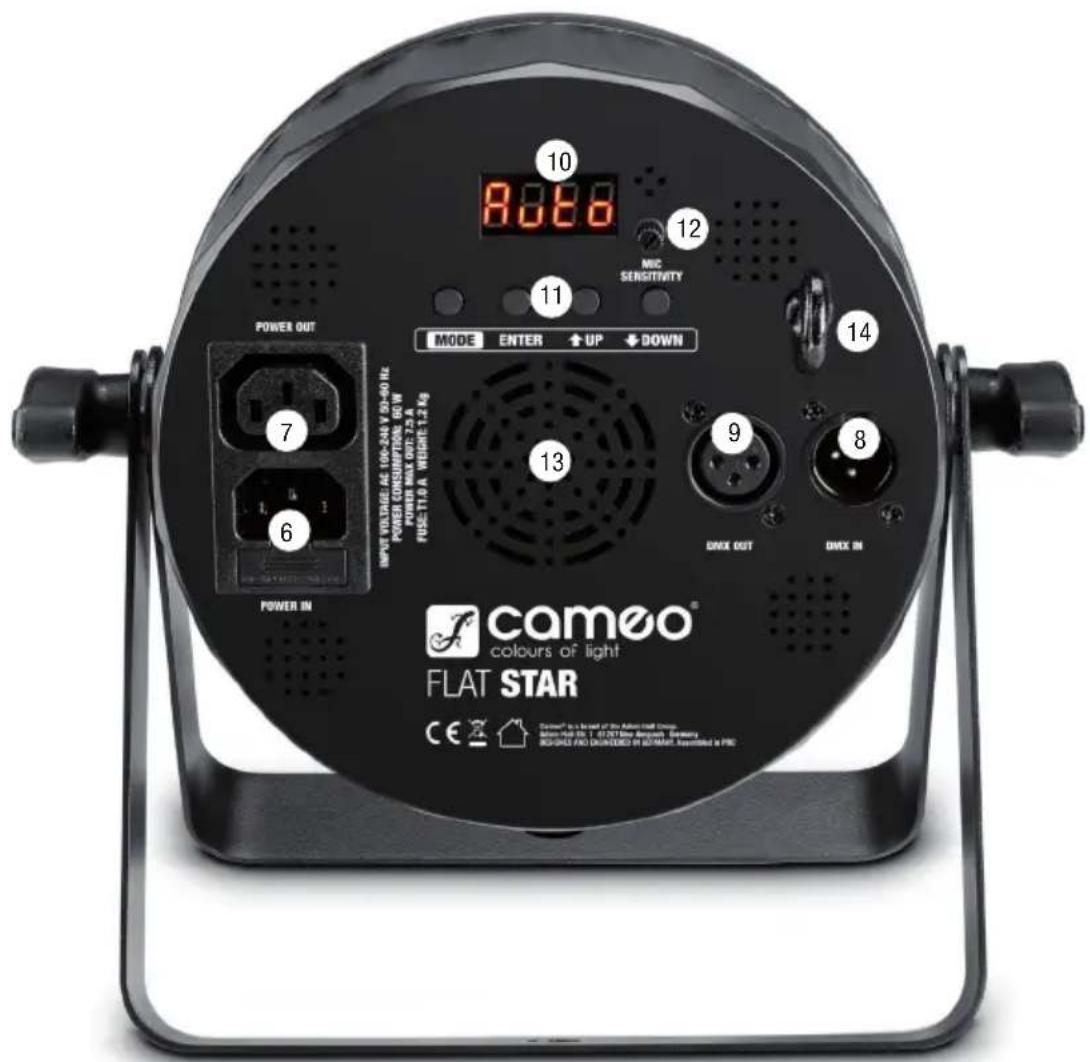
6 POWER IN
IEC mains input socket with built-in fuse holder. Operating voltage 100-240V AC/50-60Hz. A suitable IEC power cable is included.
IMPORTANT: Replace the fuse only with a fuse of the same type and of the same value according to the stamp on the housing! In the event of repeated fuse failure, please contact an authorised service centre.
7 POWER OUT
IEC power output socket. Facilitates power supply to other CAMEO lights. Ensure that the total current consumption of all connected devices does not exceed the value specified on the device in amperes (A).
8 DMX IN
Male 3-pin XLR socket for connection to a DMX control device (e.g. DMX console).
9 DMX OUT
Female 3-pin XLR socket for sending the DMX control signal.
10 LED DISPLAY
Displays the current operating mode and other system settings.
1 CONTROL BUTTONS
MODE: Press the MODE button to move up one level in the menu structure.
ENTER: Confirms programme selection and value changes.
UP and DOWN: Selection of the main menu items, programmes, change settings, such as programme speed and DMX address.
MIC SENSITIVITY
Control dial for setting the microphone sensitivity in standalone music-control mode, control via IR remote control and in DMX sound-control mode. Turn anti-clockwise to reduce sensitivity and clockwise to increase sensitivity.
13 HOUSING FAN
In order to avoid overheating of the device, ensure that the fan is not obstructed and that air can circulate freely.
14 SECURING LUG
Eyelet for safety rope. Overhead installation must only be carried out by qualified personnel. The spotlight must be fitted with a suitable safety rope to ensure that it does not fall down.
OPERATION
A few seconds after connecting to the mains, the effects spotlight is ready for operation and the previously selected operating mode is activated. During the start-up process, the software version is displayed briefly (Vx.xx).
To access the top level of the menu structure, press the MODE button several times if necessary. The display now shows one of the main menu items, Addr (DMX address), chAn (DMX modes), ModE (stand-alone modes) Set (system settings) or information (displays system software version). To select one of the main menu items, use the UP and DOWN keys and confirm with ENTER.
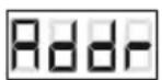
ACTIVATING DMX-CONTROL, CONFIGURING DMX START-ADDRESS (Addr)
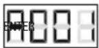
As previously described, use the UP and DOWN buttons to select the menu item Addr and confirm with ENTER. The currently configured DMX start address will now be displayed. Using the UP and DOWN buttons, configure the desired DMX start address and press ENTER to confirm.
ENTER UP/DOWN
SETTING DMX MODE (chAn)
As previously described, use the UP and DOWN buttons to select the menu item chAn and confirm with ENTER. The currently configured DMX mode is now displayed (3ch1, 3ch2, 07ch, 12ch, 13ch). Using the UP and DOWN buttons, configure the desired DMX mode and press ENTER to confirm. Tables with the channel assignment of the different DMX modes can be found in these instructions under DMX CONTROL.
->ENTER->
UP/DOWN
STADALONE MODES (ModE)
As previously described, use the UP and DOWN buttons to select the menu item ModE and confirm with ENTER. Use the UP AND DOWN buttons to select the desired stand-alone mode and confirm with ENTER (Auto = programmes with automatic control, Soun = music-controlled programmes, SLAV = master/slave mode, StAt = static mode to set a 'scene').
->ENTER->
UP/DOWN
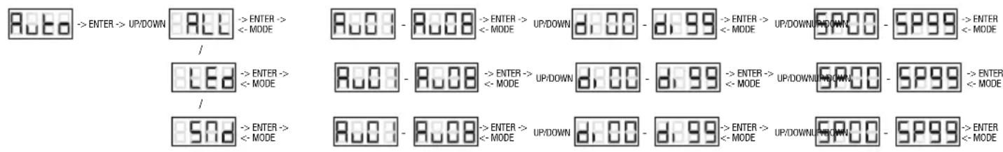
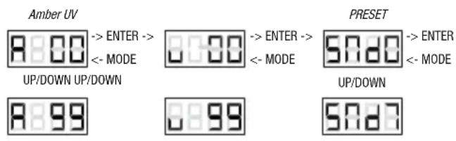
AUTOMATIC CONTROL (Auto)
In the main menu, use the UP and DOWN buttons to select the menu item ModE and confirm with ENTER, then select Auto and confirm again with ENTER. Use the UP and DOWN buttons to select the desired category from the three different programme categories ALL, LED and SMD and confirm with ENTER (ALL = centre LEDs RGBWA+UV plus SMD LED ring, LED = centre LEDs RGBWA+UV, SMd = SMD LED ring). Using the UP and DOWN buttons, you can now select one of the auto programmes from the respective programme category (Au01-Au08). After you have confirmed the entry by pressing ENTER, use the UP and DOWN buttons to adjust the overall brightness of the centre LEDs from di00 to di99 and confirm with ENTER (brightness of the SMD LED ring is not adjustable). Use the UP and DOWN buttons to select the desired programme run speed in the selected menu item (SP00 = minimum speed, SP99 = maximum speed). Confirm with ENTER. If the operating buttons are inactive for approximately one minute, the display changes to 'Auto'.
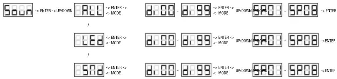
MUSIC-CONTROLLED PROGRAMMES (Soun)
In the main menu, use the UP and DOWN buttons to select the menu item ModE and confirm with ENTER, then select Soun and confirm again with ENTER. Use the UP and DOWN buttons to select the desired category from the three different programme categories ALL, LED and SMD and confirm with ENTER (ALL = centre LEDs RGBWA+UV plus SMD LED ring, LED = centre LEDs RGBWA+UV, SMd = SMD LED ring). Use the UP and DOWN buttons to adjust the overall brightness of the centre LEDs from di00 to di99 and confirm with ENTER (brightness of the SMD LED ring is not adjustable). Using the UP and DOWN buttons, you can now select one of the music-controlled programmes from the respective programme category (SP01-SP08). The sensitivity with which the programmes react to sound (bass impulses) can be set as required using the MIC SENSITIVITY control. Turn anti-clockwise to reduce sensitivity and clockwise to increase sensitivity. If the operating buttons are inactive for approximately one minute, the display changes to 'Soun'.
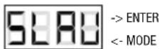
In the main menu, use the UP and DOWN buttons to select the menu item ModE, confirm with ENTER and then activate the slave mode, by selecting the menu item SLAV by using UP AND DOWN and confirm with ENTER. Connect the slave and the master unit (same model) with a DMX cable (Master = DMX OUT, Slave = DMX IN) and enable one of the standalone modes on the master unit (automatic-control, music-controlled programmes, colour-blend, static). Now the slave unit will follow the master unit.
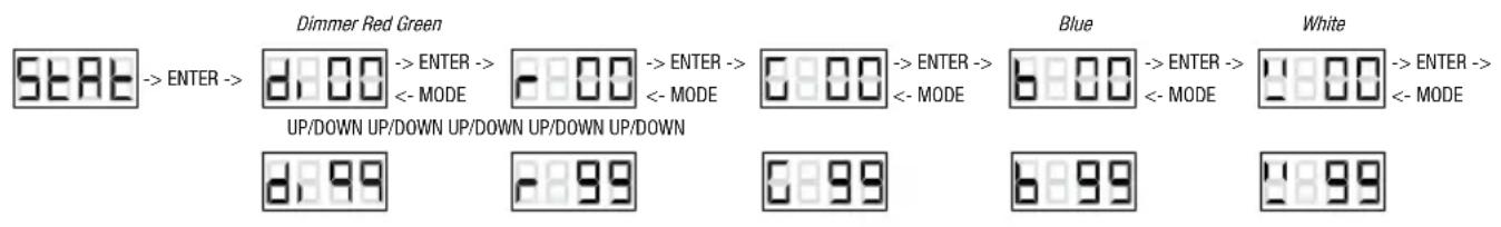
STATIC MODE (Stat)
The static mode enables you to adjust the brightness of the 6 colours of the RGBWA+UV centre LEDs separately and thus create an almost unlimited number of different colours (colour mixing). In addition, one of the 7 colour presets (7 presets + blackout) of the SMD LED ring can be activated. From the main menu, use UP and DOWN to select the menu item ModE, confirm with ENTER and then use UP and DOWN to select the menu item StAt and confirm with ENTER. Now you can use the UP and DOWN buttons to adjust the overall brightness of the centre LEDs from di00 to di99. Press ENTER to confirm. Now adjust the brightness for red, green, blue, white, amber and UV in the same way. After the setting for UV is confirmed with the ENTER key, one of the seven colour presets for the SMD-LED can be selected with the UP and DOWN buttons (SMd0 = blackout, 1 = red, 2 = green, 3 = blue, 4 = yellow, 5 = magenta, 6 = cyan, 7 = white). Confirm with ENTER.
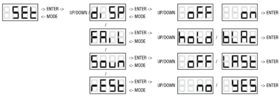
SYSTEM SETTINGS (SET)
The menu item System settings enables shut-down of the display, display of mode status in the event of DMX signal fault, configuration of the spotlight in music-controlled programmes mode and reset of all settings. Use UP and DOWN to select the menu item SET from the main menu and confirm with ENTER. Now select the desired menu item with UP and DOWN and edit it as required (select with UP and DOWN, press ENTER).
| System settings (Set) | ||||
| diSP = Display | shutdown | on = disp | ay shuts down after approx. 30 seconds of inactivity | |
| oFF = Display | shut down disabled | |||
| FAiL = operating | status with DMX signal fault | hoLd = last DMX command will be retained | ||
| bLAc = Blackout | ||||
| Soun = | Operation of the spotlight in music-controlled programmes when silent | LAST = The last scene will be retained | ||
| oFF = Blackout | ||||
| rEST = reset to factory settings | no = Do not perform reset by pressing ENTER | |||
| YES | = Perform reset by pressing ENTER | |||
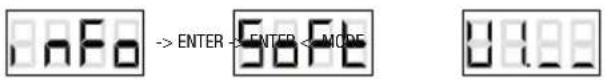
SYSTEM SOFTWARE (inFo)
Use UP and DOWN to select the menu item inFO from the main menu and confirm with ENTER. Now press ENTER again to display the software version.
DISPLAY ORIENTATION
The orientation of the display characters can be rotated by 180^ by pressing and holding the MODE and DOWN buttons simultaneously for approximately one second.
IR REMOTE CONTROL
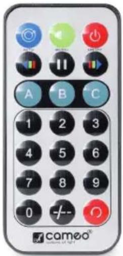
| Aim the infrared remote control directly at the infrared sensor on the front of the lamp. The maximum range is approximately 8 metres. In DMX and slave modes, the spotlight's IR sensor is deactivated. | ||
| ON/OFF | Blackout | The blackout button is used to switch off the centre LEDs and the SMD LED ring, regardless of operating mode enabled via the remote control. Press the blackout button again to reactivate the previously selected mode. |
| AUTO | Auto programme | Press the AUTO button to activate the previously selected auto programme. Repeated pressing activates each of the auto programmes 01 to 08. Category selection is performed with buttons A, B and C (A = centre LEDs RGBWA+UV plus SMD LED ring, B = centre LEDs RGBWA+UV, C = SMD LED ring). Programme speed is configured using the arrow keys (left arrow = slower, right arrow = faster). |
| MUSIC | Music-control | Press the MUSIC button to activate the previously selected music-controlled programme. Repeated pressing activates each of the music-controlled programmes 01 to 08. Category selection is performed with buttons A, B and C (A = centre LEDs RGBWA+UV plus SMD LED ring, B = centre LEDs RGBWA+UV, C = SMD LED ring). Adjust the microphone sensitivity with MIC SENSITIVITY knob on the device. |
| No function | ||
| Programme speed | Programme speed is configured using the arrow keys (left arrow = slower, right arrow = faster). | |
| A | Centre LEDs + SMD LEDs | Press button A to activate the centre LEDs and the SMD LED ring for stand-alone modes auto programmes, music-control and static mode. |
| B | Centre LEDs | Press button B to activate the centre LEDs for stand-alone modes auto programmes, music-control and static mode. |
| C | SMD LEDs | Press button C to activate the SMD LED ring for stand-alone modes auto programmes, music-control and static mode. |
| 09- | Static mode | Press one of the buttons 1 to 7 to activate the static mode and one of the 7 colour presets (1 = red, 2 = green, 3 = blue, 4 = yellow, 5 = magenta, 6 = cyan, 7 = white. Buttons 8, 9 and 0 are non-functioning). |
| No function | ||
| No function | ||
INSTALLATION AND MOUNTING
Thanks to its integrated double bracket, the lamp can be positioned in a suitable location on a level surface. Installation on a traverse is possible with a suitable traverse clamp (not supplied). Ensure firm connection to the mounting bracket and secure the lamp to the the securing lug (A) with a suitable safety cable.
Important note: Overhead mounting requires extensive experience, including the calculation of the load limit values of the installation material and regular safety inspection of all installation materials and devices, such as lights and speakers. If you do not have these qualifications, do not attempt to perform an installation yourself. Refer instead to a qualified professional.
DMX TECHNOLOGY
DMX-512
DMX (Digital Multiplex) is the designation for a universal transmission protocol for communications between corresponding devices and controllers. A DMX controller sends DMX data to the connected DMX device(s). The DMX data is always transmitted as a serial data stream that is forwarded from one connected device to the next via the "DMX IN" and "DMX OUT" connectors (XLR plug-type connectors) that are found on every DMX-capable device, provided the maximum number of devices does not exceed 32 units. The last device in the chain needs to be equipped with a terminator (terminating resistor).
DMX CONNECTION
DMX is the common "language" via which a very wide range of types and models of equipment from various manufacturers can be connected with one another and controlled via a central controller, provided that all of the devices and the controller are DMX compatible. For optimum data transmission, it is necessary to keep the connecting cables between the individual devices as short as possible. The order in which the devices are integrated in the DMX network has no influence on the addresses. Thus the device with the DMX address 1 can be located at any position in the (serial) DMX chain: at the beginning, at the end or somewhere in the middle. If the DMX address 1 is assigned to a device, the controller "knows" that it should send all data allocated to address 1 to this device regardless of its position in the DMX network.
SERIAL CONNECTION OF MULTIPLE LIGHTS
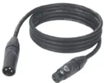
- Connect the male XLR connector (3-pin or 5-pin) of the DMX cable to the DMX output (female XLR socket) of the first DMX device (e.g. DMX-Controller).
- Connect the female 3-pin XLR connector of the DMX cable connected to the first projector to the DMX input (male 3-pin socket) of the next DMX device. In the same way, connect the DMX output of this device to the DMX input of the next device and repeat until all devices have been connected. Please note that as a rule, DMX devices are connected in series and connections cannot be shared without active splitters. The maximum number of DMX devices in a DMX chain should not exceed 32 units.
The Adam Hall 3 STAR, 4 STAR, and 5 STAR product ranges include an extensive selection of suitable cables.
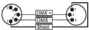
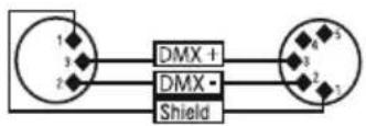
DMX CABLES
When fabricating your own cables, always observe the illustrations on this page. Never connect the shielding of the cable to the ground contact of the plug, and always make certain that the shielding does not come into contact with the housing of the XLR plug. If the shielding is connected to the ground, this can lead to short-circuiting and system malfunctions.
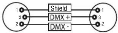
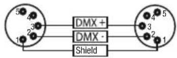
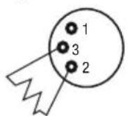
Pin Assignment
DMX cable with 3-pin XLR connectors:
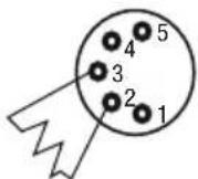
DMX cable with 5-pin XLR connectors (pin 4 and 5 are not used):
DMX TERMINATORS (TERMINATING RESISTORS)
To prevent system errors, the last device in a DMX chain needs to be equipped with a terminating resistor (120 ohm, 1/4 Watt).
3-pin XLR connector with a terminating resistor: K3DMXT3
5-pin XLR connector with a terminating resistor: K3DMXT5
Pin Assignment
3-pin XLR connector:
5-pin XLR connector:
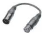
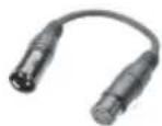
DMX ADAPTER
The combination of DMX devices with 3-pin connectors and DMX devices with 5-pin connectors in a DMX chain is possible with suitable adapters.
Pin Assignment
DMX Adapter 5-pin XLR male to 3-pin XLR female: K3DGF0020
Pins 4 and 5 are not used.
Pin Assignment
DMX Adapter 3-pin XLR male to 5-pin XLR female: K3DHM0020
Pins 4 and 5 are not used.
TECHNICAL DATA
Product number: CLFLATSTAR
| Product type: LED effects | |
| Type: 2-in-1 effect spotlight | |
| Colour spectrum centre LEDs: RGBWA+UV | |
| Number of centre LEDs: 3 | |
| LED type centre LEDs: 12W 6-in-1 | |
| Colour spectrum SMD LED ring: RGB | |
| Number of SMD LED rings: 27 | |
| LED type SMD LED ring: 0.5W Tri | |
| DMX input: 3-pin male XLR | |
| DMX output: 3-pin female XLR | |
| DMX mode: 3-Channel 1, 3-channel 2, 7-channel, 12-channel, 13-channel | |
| DMX functions: dimmer, auto programmes, pattern, strobe, colour macro, RGBWA+UV, SMD LED ring | |
| Standalone functions: | auto programmes, sound programmes, master/slave, static mode |
| Control: | DMX512, IR remote control |
| Operating controls: | Mode, Enter, Up, Down, IR Remote Control, Mic Sensitivity |
| Display elements: | 4-digit LED display |
Power connection: IEC input
IEC output (max. 7.5 A)
Operating voltage: 100-240 V AC, 50-60 Hz
Power consumption: 60W
Fuse: T1A / 250 V (5 x 20mm)
Ambient temperature (in operation): 10 - 40^
Relative air humidity: < 85% , non-condensing
Housing material: ABS/metal
Housing colour: black
Weight: 1.2kg
Additional features: adjustable mounting bracket, IR remote control included
MANUFACTURER'S DECLARATIONS
MANUFACTURER'S WARRANTY & LIMITATIONS OF LIABILITY
You can find our current warranty conditions and limitations of liability at: https://cdn-shop.adamhall.com/media/pdf/Manufacturers-Declarations-CAMEO DE EN ES FR.pdf. To request warranty service for a product, please contact Adam Hall GmbH, Adam-Hall-Str. 1, 61267 Neu Anspach / Email: Info@adamhall.com / +49 (0)6081 / 9419-0.

CORRECT DISPOSAL OF THIS PRODUCT
(valid in the European Union and other European countries with a differentiated waste collection system)
This symbol on the product, or on its documents indicates that the device may not be treated as household waste. This is to avoid environmental damage or personal injury due to uncontrolled waste disposal. Please dispose of this product separately from other waste and have it recycled to promote sustainable economic activity. Household users should contact either the retailer where they purchased this product, or their local government office, for details on where and how they can recycle this item in an environmentally friendly manner. Business users should contact their supplier and check the terms and conditions of the purchase contract. This product should not be mixed with other commercial waste for disposal.
FCC STATEMENT
This device complies with Part 15 of the FCC Rules. Operation is subject to the following two conditions:
(1) This device may not cause harmful interference, and
(2) This device must accept any interference received, including interference that may cause undesired operation
CE Compliance
Adam Hall GmbH states that this product meets the following guidelines (where applicable):
R&TTE (1999/5/EC) or RED (2014/53/EU) from June 2017
Low voltage directive (2014/35/EU)
EMV directive (2014/30/EU)
RoHS (2011/65/EU)
The complete declaration of conformity can be found at www.adamhall.com.
Furthermore, you may also direct your enquiry to info@adamhall.com.
DEUTSCH
DMX-Adapter 5-Pol XLR male auf 3-Pol XLR female: K3DGF0020
PROJECTEUR MULTI-EFFETS A LED 2 EN 1
CLFLATSTAR
FONCTIONS DE PILOTAGE :
Entree DMX:Embase XLR 3 broches male
Puisance absorbee: 60W
Fusible : T1A / 250 V (5 x 20 mm)
(Valid in the European Union and other European countries with waste separation)
Alternatively, you can use the following two methods to find a solution.
POLSKI
Gratulujemy wyboru!
Centralne diody LED 6-w-1.
3 x dioda LD RGBWA+UV 12 W.
Pierscien swietlny LED SMD.
27 x dioda LED 0,5 W RGB.
OBSLUGA:
TRYBY PRACY STANDALONE (ModE)
| 9 | Colour 6-in-1 LEDs | Colour 6-in-1 LEDs | Table 6-in-1 LEDs | Macro 6-in-1 LEDs | Color 6-in-1 LEDs | Macro 6-in-1 LEDs |
| 10 | Colour RGBWA+UV | Colour RGBWA+UV | Table 6-in-1 LEDs | Macro RGBWA+UV | Color RGBWA+UV | Table 6-in-1 LEDs |
| 11 | SMD | SMD | CH3-8 | SMD | SMD | CH3-8 |
| 12 | Auto Program Speed/ | 12 | Auto Program Speed/ | 12 | Auto Program Speed/ | 12 |
| 13 | Auto Program Speed/ | 13 | Auto Program Speed/ | 13 | Auto Program Speed/ | 13 |
| Colour Macros G-in-1 LEDs | ||
| 000 - 05 Colour off | ||
| 006 - 013 Red | ||
| 014 - 021 Amber | ||
| 022 - 029 Yellow warm | ||
| 030 - 037 Yellow | ||
| 038 - 045 Green | ||
| 046 - 053 Turquoise | ||
| 054 - 061 Cyan | ||
| 062 - 069 Blue | ||
| 070 - 077 Lavender | ||
| 078 - 085 Maive | ||
| 086 - 093 Magenta | ||
| 094 - 101 Pink | ||
| 102 - 109 Warm White | ||
| 110 - 117 White | ||
| 118 - 125 Cold White | ||
| 126 - 127 | Colour Jumping | |
| 128 - 191 | Colour Jumping | |
| 192 - 255 | Speed slow -> fast /Colour 1->12 | |
| Colour Macros SMD LEDs | |
| 000 - 031 Light off | |
| 032 - 063 Red | |
| 064 - 095 Green | |
| 096 - 127 Blue | |
| 128 - 159 Yellow | |
| 160 - 191 Magenta | |
| 192 - 223 Cyan | |
| 224 - 255 White | |