
Studio PAR 64 CAN - Lighting Cameo - Free user manual and instructions
Find the device manual for free Studio PAR 64 CAN Cameo in PDF.
| Product type | Quad-color LED projector (RGBA) |
| Brand | Cameo |
| Model | Studio PAR 64 CAN |
| Reference | CLPST64RGBAQ8W |
| Number of LEDs | 18 x 8 W QUAD RGBA |
| Beam angle | 25° |
| Power consumption | 170 W |
| Supply voltage | 100-250 V AC, 50/60 Hz |
| Fuse | F2A / 250V |
| Weight | 4.5 kg |
| Dimensions (L x W x H) | 255 x 230 x 220 mm |
| DMX modes | 2 CH, 3 CH1, 3 CH2, 4 CH, 7 CH |
| DMX protocol | DMX-512 USITT |
| DMX connectors | 3-pin XLR (male input, locking female output) |
| Main functions | Static color, color macro, color jump, color fade, automatic, sound control, strobe, master/slave, dimming |
| Cleaning | Dry cloth |
| Installation | Stable mounting, do not block ventilation slots |
| Safety | Do not open (risk of electric shock); do not look directly at the beam closer than 40 cm |
| Reparability | Replace fuse only with same type; repairs by authorized personnel only |
| Warranty | Manufacturer limited warranty (2 to 5 years depending on product) |
| General information | Professional use; CE compliance |
Frequently Asked Questions - Studio PAR 64 CAN Cameo
User questions about Studio PAR 64 CAN Cameo
0 question about this device. Answer the ones you know or ask your own.
Ask a new question about this device
Download the instructions for your Lighting in PDF format for free! Find your manual Studio PAR 64 CAN - Cameo and take your electronic device back in hand. On this page are published all the documents necessary for the use of your device. Studio PAR 64 CAN by Cameo.
USER MANUAL Studio PAR 64 CAN Cameo
Thank you for choosing Cameo Lights!
We have designed this product to give you reliable operation over many years.
Please, take a few moments to read these instructions carefully, as we want you to enjoy your new Cameo Lights products quickly and to the fullest.
Further information about Cameo Lights check our website WWW.CAMEOLIGHT.COM
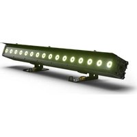
STUDIO PAR 64 CAN
18 x 8W QUAD COLOUR LED PAR CAN RGBA CLPST64RGBAQ8W

natural_image
Technical line drawing of a mechanical device with circular components and mounting brackets (no text or symbols)PREVENTIVE MEASURES:
- Please read these instructions carefully.
- Keep all information and instructions in a safe place.
- Follow the instructions.
- Observe all safety warnings. Never remove safety warnings or other information from the equipment.
- Use the equipment only in the intended manner and for the intended purpose.
- Use only sufficiently stable and compatible stands and/or mounts (for fixed installations). Make certain that wall mounts are properly installed and secured. Make certain that the equipment is installed securely and cannot fall down.
- During installation, observ e the applicable safety regulations for your country.
- Never install and operate the equipment near radiators, heat registers, ovens or other sources of heat. Make certain that the equipment is always installed so that is cooled sufficiently and cannot overheat.
- Never place sources of ignition, e.g., burning candles, on the equipment.
- Ventilation slits must not be blocked.
- Do not use this equipment in the immediate vicinity of water (does not apply to special outdoor equipment - in this case, observe the special instructions noted below. Do not expose this equipment to flammable materials, fluids or gases.
- Make certain that dripping or splashed water cannot enter the equipment. Do not place containers filled with liquids, such as vases or drinking vessels, on the equipment.
- Make certain that objects cannot fall into the device.
- Use this equipment only with the accessories recommended and intended by the manufacturer.
- Do not open or modify this equipment.
- After connecting the equipment, check all cables in order to prevent damage or accidents, e.g., due to tripping hazards.
- During transport, make certain that the equipment cannot fall down and possibly cause property damage and personal injuries.
- If your equipment is no longer functioning properly, if fluids or objects have gotten inside the equipment or if it has been damaged in anot her way, switch it off immediately and unplug it from the mains outlet (if it is a powered device). This equipment may only be repaired by authorized, qualified personnel.
- Clean the equipment using a dry cloth.
- Comply with all applicable disposal laws in your country. During disposal of packaging, please separate plastic and paper/cardboard.
- Plastic bags must be kept out of reach of children.
FOR EQUIPmENT THaT CONNECTS TO THE POWER maINS:
-
CAUTION: If the power cord of the device is equipped with an earthing contact, then it must be connected to an outlet with a protective ground. Never deactivate the protective ground of a power cord.
-
If the equipment has been exposed to strong fluctuations in temperature (for example, after transport), do not switch it on immediately. Moisture and condensation could damage the equipment. Do not switch on the equipment until it has reached room temperature.
-
Before connecting the equipment to the power outlet, first verify that the mains voltage and frequency match the values specified on the equipment. If the equipment has a voltage selection switch, connect the equipment to the power outlet only if the equipment values and the mains power values match. If the included power cord or power adapter does not fit in your wall outlet, contact your electrician.
-
Do not step on the power cord. Make certain that the power cable does not become kinked, especially at the mains outlet and/or power adapter and the equipment connector.
-
When connecting the equipment, make certain that the power cord or power adapter is always freely accessible. Always disconnect the equipment from the power supply if the equipment is not in use or if you want
SAFETY:
to clean the equipment. Always unplug the power cord and power adapter from the power outlet at the plug or adapter and not by pulling on the cord. Never touch the power cord and power adapter with wet hands.
- Whenever possible, avoid switching the equipment on and off in quick succession because otherwise this can shorten the useful life of the equipment.
- IMPORTANT INFORMATION: Replace fuses only with fuses of the same type and rating. If a fuse blows repeatedly, please contact an authorised service centre.
- To disconnect the equipment from the power mains completely, unplug the power cord or power adapter from the power outlet.
-
If your device is equipped with a Volex power connector, the mating Volex equipment connector must be unlocked before it can be removed. However, this also means that the equipment can slide and fall down if the power cable is pulled, which can lead to personal injuries and/or other damage. For this reason, always be careful when laying cables.
-
Unplug the power cord and power adapter from the power outlet if there is a risk of a lightning strike or before extended periods of disuse.

CAUTION:
Never remove the cover, because otherwise there may be a risk of electric shock. There are no user serviceable parts inside. Have repairs carried out only by qualified service personnel.
The lightning flash with arrowhead symbol within an equilateral triangle is intended to alert the user to the presence of uninsulated “dangerous voltage” within the product’s enclosure that may be of sufficient magnitude to constitute a risk of electrical shock.

The exclamation mark within an equilateral triangle is intended to alert the user to the presence of important operating and maintenance instructions.
CAUTION – HIGH VOLUME LEVELS WITH AUDIO PRODUCTS!
This equipment is intended for professional use. Therefore, commercial use of this equipment is subject to the respectively applicable national accident prevention rules and regulations. As a manufacturer, Adam Hall is obligated to notify you formally about the existence of potential health risks.
Hearing damage due to high volume and prolonged exposure: When in use, this product is capable of producing high sound-pressure levels (SPL) that can lead to irreversible hearing damage in performers, employees, and audience members. For this reason, avoid prolonged exposure to volumes in excess of 90 dB.
CAUTION! IMPORTANT INFORMATION ABOUT LIGHTING PRODUCTS
- Do not look into the beam from a distance of less than 40 cm.
- Do not stare into the beam for extended periods at short-to-medium distances.
- Do not view the beam directly with optical instruments such as magnifiers.
- Under some circumstances, stroboscopic effects may trigger epileptic seizures in sensitive individuals! For this reason, persons who suffer from epilepsy should always avoid places where strobe lights are used.
INTRODUCTION:
CONTROL FEATURES
18 X 8W QUAD COLOUR LED PAR CAN RGBA
(CLPST64RGBAQ8W)
• 2 CH, 3 CH1, 3 CH2, 4 CH, 7 CH DMX Modes
- Individual control of Red, Green, Blue and Amber colour (RGBA in 1)
FEATURES
• 18 Ultra bright 8W QUAD colour LEDs
• Sound control via internal microphone
- Colour jumping speed and strobe effect adjustable via control panel
- Multi-colour changes
- Master/Slave functions
• Rugged compact housing
• Power consumption: 170 W
- Beam angle 25^
- Long life LEDs
OPERATING INSTRUCTIONS
The Cameo LED CAN is a DMX-512 controllable, colour mixing spot made up of high efficiency and super bright LED's. There are four colours (red, green, blue and amber) whose intensity can be controlled individually allowing the creation of an unlimited range of colours. The Cameo LED light will operate in Stand-alone, Master/Slave, Sound controlled and via DMX-512 control.
BACK PANEL:
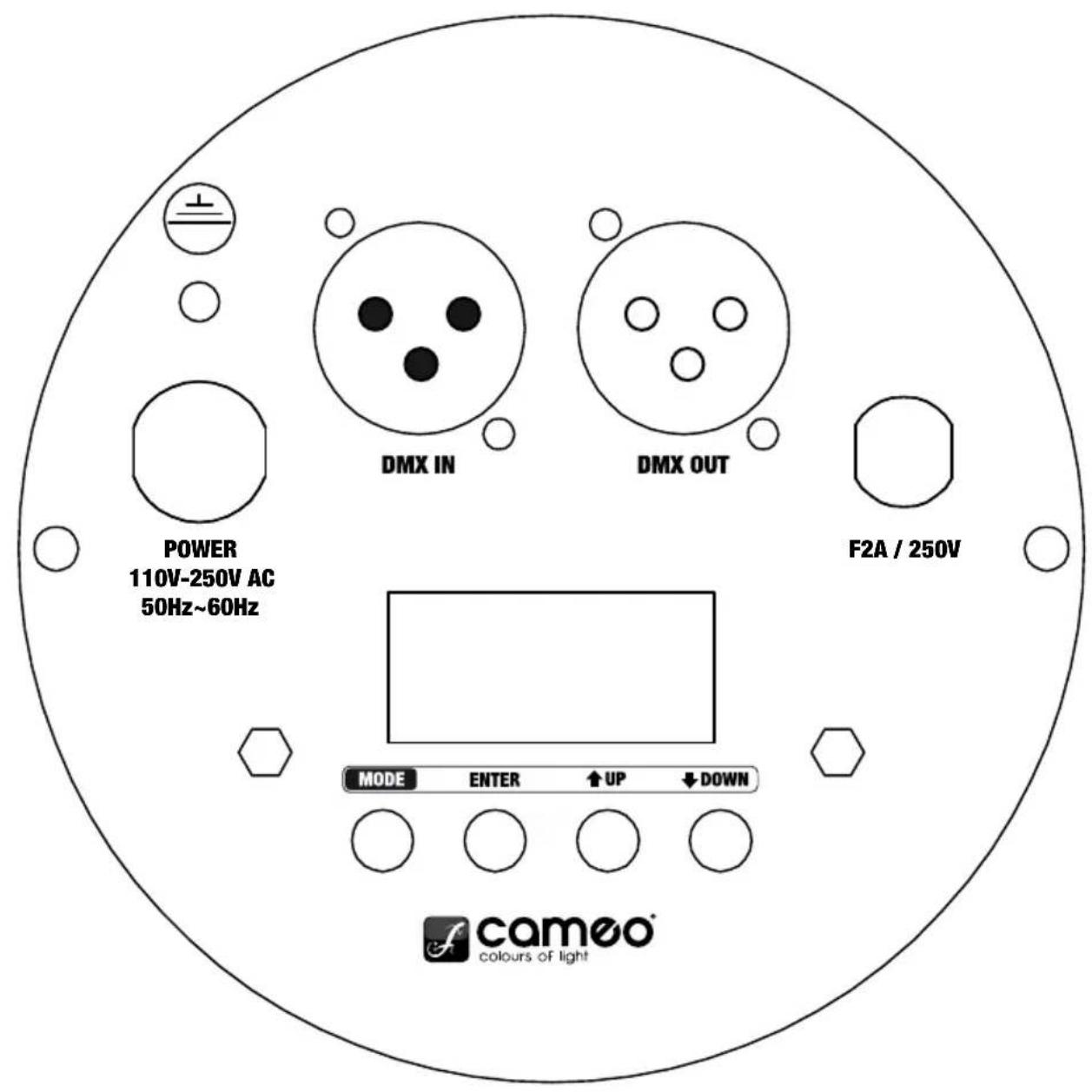
MODE SELECTION:
STATIC COLOUR MODE
Press the MODE button repeatedly if necessary to select the Static Colour Mode (CXXX), then press the ENTER button (2. digit blinks) to choose one of the static colours or the strobe function by using the UP and DOWN buttons. C1 represents Red, C2 = Green, C3 = Blue, C4 = Amber and CF = Strobe.
Press ENTER again (3. and 4. digit blink) to adjust the brightness of the pre-selected colour (CX00 - CX99) and the strobe speed (CF00 - CF99) by using the UP and DOWN buttons. Press ENTER to confirm.
Examples: If you set C1, C2, C3 and C4 to zero, the Quad Par Can will have no LEDs on (blackout).
If you set C1 to 99 and C2, C3 and C4 to zero, the colour will be 100% Red.
RED
Brightness C100 - C199
GREEN
Brightness C200 - C299
BLUE
Brightness C300 - C399
AMBER
Brightness C400 - C499
STROBE
Speed CF00 - CF99


MODE SELECTION:
COLOUR MACRO MODE (15 COLOURS)
Press the MODE button (repeatedly, if necessary) to select the "Colour Macro" mode (CMXX). Confirm with ENTER and then use the UP and DOWN buttons to select the desired colour. Confirm with ENTER.
Press the MODE button repeatedly if necessary to select the Colour Jumping Mode (JXXX). Press ENTER (2. digit blinks) to select the 15 colour jumping function (JUXX) or the strobe function (JFXX) by using the UP and DOWN buttons.
Press ENTER again (3. and 4. digit blink) to adjust jumping speed (JU00 - JU99) and strobe speed (JF00 - JF99) by using the UP and DOWN buttons. Press ENTER to confirm.
Note: It is possible to use the colour jumping function and the strobe function simultaneously.
RGBA 15 COLOUR
Jumping speed JU00 - JU99
STROBE
Speed JF00 - JF99
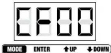
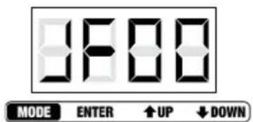
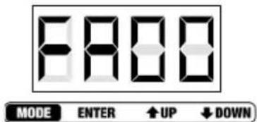
COLOUR FADING MODE
Press the MODE button repeatedly if necessary to select the Colour Fading Mode (FXXX). Press ENTER (2. digit blinks) to select the 15 colour fading function (FAXX) or the strobe function (FFXX) by using the UP and DOWN buttons. Press ENTER again (3. and 4. digit blink) to adjust fading speed (FA00 - FA99) and strobe speed (FF00 - FF99) by using the UP and DOWN buttons. Press ENTER to confirm.
Note: It is possible to use the colour fading function and the strobe function simultaneously.
RGBA 15 COLOUR
Fading speed FA00 - FA99
STROBE
Speed FF00 - FF99


MODE SELECTION:
AUTO MODE
Press the MODE button repeatedly if necessary to select the Auto Mode. The unit changes between Colour Jumping Mode and Colour Fading Mode automatically. The colour jumping and fading speed can be preadjusted by using the speed settings of the Colour Jumping and Colour Fading Modes.
SLAVE MODE
Press the MODE button repeatedly if necessary to enter the Slave Mode. Link slave units and the master unit (exclusively standalone modes) via DMX cables. The slave unit will follow in sequence with the master unit.
SOUND CONTROL MODE
Press the MODE button repeatedly if necessary to select the Sound Control Mode (SUXX). The unit will follow the beat of the music thanks to the built in microphone. Press ENTER again (3. and 4. digit blink) to adjust the sensitivity of the microphone (SU00 - SU99) by using the UP and DOWN buttons. Press ENTER to confirm.
DMX MODE SELECTION
Press the MODE button to enter DMX MODE SELECTION (repeatedly if necessary). Press ENTER (1st digit blinks) and select the desired DMX mode by using the UP and DOWN buttons. Press ENTER again to confirm. Note: See the description of the different DMX modes on the following pages of this manual.
DMX ADDRESS SETTING MODE
Press the MODE button repeatedly if necessary to enter the DMX Address Setting Mode (AXXX).
Press ENTER to access edit mode (the last 3 digits blink) and select the desired DMX start address by using the UP and DOWN buttons (A001 - A512). Press ENTER to confirm.
NOTE:
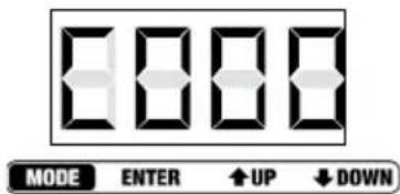
The LED display automatically turns off after about 1 minute and turns on again by pressing any of the 4 buttons.


DMx CONTROL MODE:
| 2 CHANNEL MODE | ||
| CHANNEL VALUE | FUNCTION | |
| CH1 000 - 255 | Master dimmer (0-100 %) | |
| CH2 000 - 016 | Red | |
| 017 - 033 | Green | |
| 034 - 050 | Blue | |
| 051 - 067 | Amber | |
| 068 - 084 | Yellow | |
| 085 - 101 | Cyan | |
| 102 - 118 | Lavender | |
| 119 - 135 | Pink | |
| 136 - 152 | Bright Green | |
| 153 - 169 | Magenta | |
| 170 - 186 | Turquoise | |
| 187 - 203 | Orange | |
| 204 - 220 | Bright Magenta | |
| 221 - 237 | Cold White | |
| 238 - 255 | Warm White | |
| 3 CHANNEL MODE 1 | ||
| CHANNEL VALUE | FUNCTION | |
| CH1 000 - 255 | Master dimmer (0-100 %) | |
| CH2 000 - 255 | Strobe (0-100%) | |
| CH3 000 - 080 | Colour-Macro | |
| 000 - 004 Blackout | ||
| 005 - 010 Red | ||
| 011 - 015 | Green | |
| 016 - 020 | Blue | |
| 021 - 025 | Amber | |
| 026 - 030 | Yellow | |
| 031 - 035 | Cyan | |
| 036 - 040 | Lavender | |
| 041 - 045 | Pink | |
| 046 - 050 | Bright Green | |
| 051 - 055 Magenta | ||
DMx CONTROL MODE:
| 3 CHANNEL MODE 1 | ||
| CHANNEL VALUE | FUNCTION | |
| 056 - 060 Turquoise | ||
| 061 - 065 Orange | ||
| 066 - 070 Bright Magenta | ||
| 071 - 075 Cold White | ||
| 076 - 080 Warm White | ||
| 081 - 150 | Colour Jumping Speed: slowest (081), fastest (150) | |
| 151 - 220 | Colour Fading Speed: slowest (151), fastest (220) | |
| 221 - 255 | Sound Control (Mic Sensitivity) | |
| 3 CHANNEL MODE 2 | ||
| CHANNEL VALUE | FUNCTION | |
| CH1 | 000 - 255 | RED (0-100%) |
| CH2 | 000 - 255 | GREEN (0-100%) |
| CH3 | 000 - 255 BLUE (0-100%) | |
| 4 CHANNEL MODE | ||
| CHANNEL VALUE | FUNCTION | |
| CH1 | 000 - 255 | RED (0-100%) |
| CH2 | 000 - 255 | GREEN (0-100%) |
| CH3 | 000 - 255 BLUE (0-100%) | |
| CH4 | 000 - 255 | AMBER (0-100%) |
| 7 CHANNEL MODE | ||
| CHANNEL VALUE | FUNCTION | |
| CH1 | 000 - 255 | Master dimmer (0-100 %) |
| CH2 | 000 - 255 | Strobe (0-100%) |
DMx CONTROL MODE:
| 7 CHANNEL MODE | ||
| CHANNEL VALUE | FUNCTION | |
| CH3 000 - 255 | RED (0-100%) | |
| CH4 000 - 255 | GREEN (0-100%) | |
| CH5 000 - 255 | BLUE (0-100%) | |
| CH6 000 - 255 | AMBER (0-100%) | |
| CH7 000 - 080 | Colour-Macro | |
| 000 | Colourmix CH3 - CH6 | |
| 001 - 004 | Blackout | |
| 005 - 010 | Red | |
| 011 - 015 | Green | |
| 016 - 020 | Blue | |
| 021 - 025 | Amber | |
| 026 - 030 | Yellow | |
| 031 - 035 | Cyan | |
| 036 - 040 | Lavender | |
| 041 - 045 | Pink | |
| 046 - 050 | Bright Green | |
| 051 - 055 | Magenta | |
| 056 - 060 | Turquoise | |
| 061 - 065 | Orange | |
| 066 - 070 Bright Magenta | ||
| 071 - 075 | Cold White | |
| 076 - 080 | Warm White | |
| 081 - 150 | Colour Jumping Speed: slowest (081), fastest (150) | |
| 151 - 220 | Colour Fading Speed: slowest (151), fastest (220) | |
| 221 - 255 | Sound Control (Mic Sensitivity) | |
DAISY CHAIN CONNECTION
1) Connect the (male) 3 pin connector side of the DMX cable to the output (female) 3 pin connector of the first fixture
2) Connect the end of the cable coming from the first fixture which will have a (female) 3 pin connector to the input connector of the next fixture consisting of a (male) 3 pin connector. Proceed to connect from the output as stated above to the input of the following fixture and so on.
SPECIFICATIONS:
18 X 8W QUAD COLOUR LED PAR CAN RGBA WEIGHT & DIMENSIONS (WITHOUT BRACKET)
| Length 255 mm |
| Width 230 mm |
| Height 220 mm |
| Weight 4,5 kg |
| Beam angle 25 ° |
POWER
| Power consumption 170 W |
| AC input 110 V AC - 250 V AC / 50 Hz - 60 Hz |
FUSE
| Main F2A, 250V | |
| CONTROL & PROGRAMMING | |
| DMX input | 3-pin XLR male socket |
| DMX output | Locking 3-pin XLR female socket |
| Protocols | DMX-512 USITT |
| DMX channel modes | 2 CH, 3 CH1, 3 CH2, 4 CH, 7 CH |
DMx LINKING:
DMX-512
DMX (Digital Multiplex) is a universal protocol used as a form of communication between intelligent fixtures and controllers. A DMX controller sends DMX data instructions from the controller to the fixture. DMX data are sent as serial data that travel from fixture to fixture via the "DMX IN" and "DMX OUT" XLR terminals located on all DMX fixtures (most controllers only have a "DMX OUT" terminal).
DMX LINKING:
DMX is a language allowing all makes and models of different manufactures to be linked together and operate from a single controller, as long as all fixtures and the controller are DMX compliant. To ensure proper DMX data transmission, when using several DMX fixtures try to use the shortest cable path possible. The order in which fixtures are connected in a DMX line does not influence the DMX addressing. For example a fixture assigned to a DMX address of 1 may be placed anywhere in a DMX line, at the beginning, at the end, or anywhere in the middle. When a fixture is assigned a DMX address of 1, the DMX controller knows to send DATA assigned to address 1 to that unit, no matter where it is located in the DMX chain.

natural_image
Black cable with two connectors, one male and one female, against a plain white background (no text or symbols visible)Please check out our comprehensive DMX cable choices out of our Adam Hall product lines 3 STAR, 4 STAR and 5 STAR
Keep in mind that DMX connections must be daisy chained. To avoid malfunction, DMX cabling should not be divided in several lines without the use of an active splitter.
DMX CABLES:
NOTICE:
- Be sure to follow figures 2 & 3 when making your own cables. Do not connect the cable's shield conductor to the ground lug or allow the shield conductor to come in contact with the XLR's outer casing. Grounding the shield could cause a short circuit and erratic behaviour.
common
DMX-512 out 3-pin XLR

DMX-512 in 3-pin XLR
SPECIAL NOTE: LINE TERMINATION:
- When longer runs of cable are used, you may need to use a terminator on the last unit to avoid erratic behaviour.

Termination reduces signal transmission problems and interference. It is always advisable to connect a DMX terminator, (resistance 120 Ohm 1/4 W) between pin 2 (DMX-) and pin 3 (DMX+) of the last fixture.
Using a cable terminator (Art. No. K3DMXT3) will decrease the possibilities of erratic behaviour.
- Some manufactures use 5-pin XLR connectors for data transmission in place of 3-pin. 5-Pin XLR fixtures may be implemented in a 3-pin XLR DMX line. When inserting standard 5-pin XLR connectors in to a 3-pin line a cable adaptor must be used. The chart below details the correct cable conversion.

MANUFACTURER'S DECLARATIONS:
MANUFACTURER'S WARRANTY
This warranty covers the Adam Hall, LD Systems, Defender, Palmer, and Cameo brands. It applies to all products distributed by Adam Hall.
This warranty declaration does not affect the statutory warranty claims against the manufacturer, but expands them with additional warranty claims vis-a-vis Adam Hall.
Adam Hall warrants that the Adam Hall product that you have purchased from Adam Hall or from an Adam Hall authorized reseller is free from defects in materials or workmanship under normal use for a period of 2 or 5 years (please inquire on a product-by-product basis) from the date of purchase.
The warranty period begins on the date on which the product was purchased, proof of which must be produced (through presentation of the invoice or the delivery note with the date of purchase) in the event of a warranty claim. Should products of the brands named above be in need of repair within the limited warranty period, you are entitled to warranty service according to the terms and conditions stated here.
During the Limited Warranty Period, Adam Hall will repair or replace the defective component parts or the product. In the event of repair or replacement during the Limited Warranty Period, the replaced original parts and/or products become property of Adam Hall.
In the unlikely event that the product which you purchased has a recurring failure, Adam Hall has the right, at its discretion, to replace the defective product with another product, provided that the new product is at least equivalent to the product being replaced with regard to the technical specifications.
Adam Hall does not warrant that the operation of this product will be uninterrupted or error-free. Adam Hall is not responsible for damage that occurs as a result of your failure to follow the instructions included with the Adam Hall branded product. The manufacturer's warranty does not cover – expendable parts (e.g., rechargeable batteries) - products from which the serial number has been removed or with a serial number that has been damaged as a result of an accident - damage due to improper use, user error or other external reasons - damage to devices operated outside the usage parameters stated in the documentation included with the product - damage due to the use of replacement parts not manufactured, sold or recommended by Adam Hall, - damage due to modification or servicing by anyone other than Adam Hall.
These terms and conditions constitute the complete and exclusive warranty agreement between you and Adam Hall regarding the Adam Hall branded product you have purchased.
MANUFACTURER'S DECLARATIONS:
LIMITATION OF LIABILITY
If your Adam Hall branded hardware product fails to work as warranted above, your sole and exclusive remedy shall be repair or replacement. Adam Halls' maximum liability under this limited warranty is expressly limited to the lesser of the price you have paid for the product or the cost of repair or replacement of any components that malfunction under conditions of normal use.
Adam Hall is not liable for any damages caused by the product or the failure of the product, including any lost profits or savings or special, incidental, or consequential damages. Adam Hall is not liable for any claim made by a third party or made by you for a third party.
This limitation of liability applies whether damages are sought, or claims are made, under this Limited Warranty or as a tort claim (including negligence and strict product liability), a contract claim, or any other claim, and cannot be rescinded or changed by anyone. This limitation of liability will be effective even if you have advised Adam Hall or an authorized representative of Adam Hall of the possibility of any such damages, but not, however, in the event of claims for damages in connection with personal injuries.
This manufacturer's warranty grants you specific rights; depending on jurisdiction (nation or state), you may be entitled to additional claims. You are advised to consult applicable state or national laws for a full determination of your rights.
REQUESTING WARRANTY SERVICE
To request warranty service for the product, contact Adam Hall or the Adam Hall authorized reseller from which you purchased the product.
EC DECLARATION OF CONFORMITY
The equipment marketed by Adam Hall complies (where applicable) with the essential requirements and other relevant specifications of Directives 1999/5/EC (R&TTE), 2004/108/EC (EMC) und 2006/95/EC (LVD). Additional information can be found at www.adamhall.com.
MANUFACTURER'S DECLARATIONS:
PROPER DISPOSAL OF THIS PRODUCT
(Valid in the European Union and other European countries with waste separation)

This symbol on the product, or the documents accompanying the product, indicates that this appliance may not be treated as household waste. This is to avoid environmental damage or personal injury due to uncontrolled waste disposal. Please dispose of this product separately from other waste and have it recycled to promote sustainable economic activity.
Household users should contact either the retailer where they purchased this product, or their local government office, for details on where and how they can recycle this item in an environmentally friendly manner. Business users should contact their supplier and check the terms and conditions of the purchase contract. This product should not be mixed with other commercial wastes for disposal.
ENVIRONMENTAL PROTECTION AND ENERGY CONSERVATION
Energy conservation is an active contribution to environmental protection. Please turn off all unneeded electrical devices. To prevent unneeded devices from consuming power in standby mode, disconnect the mains plug.
Adam Hall GmbH, all rights reserved. The technical data and the functional product characteristics can be subject to modifications. The photocopying, the translation, and all other forms of copying of fragments or of the integrity of this user's manual is prohibited.
The Ground Truth image displays a single, solid horizontal line. According to Rule 2 (UNDERSCORE & LINE RULES), if the GT contains lines used for stylistic emphasis or as background (like ruled paper), the OCR result must ignore them. The line in the GT is clearly a stylistic or background line, not a placeholder for text. Therefore, the OCR should not have output any underscores. Outputting `____` constitutes an error under Rule 2, as it hallucinates placeholder symbols where none are semantically intended. No punctuation mismatch or formatting transformation applies here.
The image contains no text or characters.
FRANCAISDEUTSCHE
ENGLISH
ITALIANOPOL
IESPA
natural_image
Black cable with two connectors and three pins, no visible text or symbolsBrightness C100 - C199
VERT
Brightness C200 - C299
BLEU
Brightness C300 - C399
AMBRE
Brightness C400 - C499
EFFET STROBOSCOPIQUE
Speed CF00 - CF99


SÉLECTION DE MODE :
MODE COLOUR MACRO (15 COULEURS)
natural_image
Black cable with two connectors and a 5-pin connector, no visible text or symbolsDÉCLARATION DE CONFORMITÉ CE
MISE AU REBUT DE CE PRODUIT
natural_image
Black cable with two connectors and a 5-pin connector, no visible text or symbolsnatural_image
Technical line drawing of a mechanical device with circular components and mounting brackets (no text or symbols)ŚRODKI OSTROŻNOŚCI:
WAGA I WYMIARY LAMPY PAR 18 X 8 W QUAD COLOUR LED RGBA (BEZ UCHWYTU)
natural_image
Black cable with two connectors and a connector pin, no visible text or symbolsGWARANCJA PRODUCENTA
DEKLARACJA ZGODNOŚCI WE
- m = 311
m = 311
m = 311
m = 311 - U
m = 311
m = 311
m = 311
m = 311
m = 311 - F
RA
NC
AIS
GDB
三厂
TSC
CHE
ENO
GLI
SH
[Non-Text]
m = 311
m = 311
m = 311
m = 311
m = 311
U - IT
ALI
IAN
OP
0
1 - IE
S
P
A
natural_image
Black and white photo of a coiled black electrical connector with two connectors (no text or symbols visible)natural_image
Stylized white lemniscus logo on black background, enclosed in a rounded square frame (no text or symbols)WWW.CAMEOLIGHT.COM

- Thank you for choosing Cameo Lights!
- STUDIO PAR 64 CAN
- PREVENTIVE MEASURES:
- FOR EQUIPmENT THaT CONNECTS TO THE POWER maINS:
- SAFETY:
- CAUTION:
- CAUTION – HIGH VOLUME LEVELS WITH AUDIO PRODUCTS!
- CAUTION! IMPORTANT INFORMATION ABOUT LIGHTING PRODUCTS
- INTRODUCTION:
- CONTROL FEATURES
- X 8W QUAD COLOUR LED PAR CAN RGBA
- FEATURES
- OPERATING INSTRUCTIONS
- BACK PANEL:
- MODE SELECTION:
- STATIC COLOUR MODE
- RED
- GREEN
- BLUE
- AMBER
- STROBE
- COLOUR MACRO MODE (15 COLOURS)
- RGBA 15 COLOUR
- COLOUR FADING MODE
- AUTO MODE
- SLAVE MODE
- SOUND CONTROL MODE
- DMX MODE SELECTION
- DMX ADDRESS SETTING MODE
- NOTE:
- DMx CONTROL MODE:
- DAISY CHAIN CONNECTION
- SPECIFICATIONS:
- DMx LINKING:
- DMX-512
- DMX CABLES:
- NOTICE:
- SPECIAL NOTE: LINE TERMINATION:
- MANUFACTURER'S DECLARATIONS:
- MANUFACTURER'S WARRANTY
- LIMITATION OF LIABILITY
- REQUESTING WARRANTY SERVICE
- EC DECLARATION OF CONFORMITY
- PROPER DISPOSAL OF THIS PRODUCT
- ENVIRONMENTAL PROTECTION AND ENERGY CONSERVATION
- VERT
- BLEU
- AMBRE
- EFFET STROBOSCOPIQUE
- SÉLECTION DE MODE :
- MODE COLOUR MACRO (15 COULEURS)
- DÉCLARATION DE CONFORMITÉ CE
- MISE AU REBUT DE CE PRODUIT
- ŚRODKI OSTROŻNOŚCI:
- GWARANCJA PRODUCENTA
- DEKLARACJA ZGODNOŚCI WE
Brand : Cameo
Model : Studio PAR 64 CAN
Category : Lighting