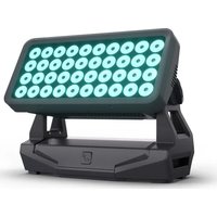
ZENIT W600 TW - Lighting Cameo - Free user manual and instructions
Find the device manual for free ZENIT W600 TW Cameo in PDF.
| Product type | Professional LED wash projector |
| Brand | Cameo |
| Model | ZENIT W600 TW |
| Dimensions (W x H x D) | 463 x 291 x 161 mm (without mounting bracket) |
| Weight | 11.9 kg (without accessories) |
| Power supply | 100-240 V AC, 50/60 Hz |
| Max power consumption | 480 W |
| Protection rating | IP65 |
| Number of LEDs | 40 (WW + CW) |
| Power per LED | 12 W |
| Beam angle | 18° (field 35°) |
| Color temperature | 2600 K - 6500 K (adjustable) |
| CRI | 93 @ 4000 K |
| Luminous flux | 31,000 lm |
| Control functions | DMX512, W-DMX, RDM, Standalone (Auto, Static, CCT, User Color, Timer) |
| DMX modes | 1CH, 2CH-1, 2CH-2, 3CH, 4CH, 7CH |
| Connectors | XLR 5-pin DMX IN/OUT, TrueCon POWER IN/OUT |
| Display | OLED with touch keys |
| Mounting | Floor or suspended via mounting omegas (2 included) |
| Minimum distance to illuminated surface | 0.5 m |
| Minimum distance to flammable materials | 0.5 m |
| Ambient temperature | -15 °C to +40 °C |
| Maintenance and cleaning | Clean surfaces with a damp cloth. Regularly clean ventilation openings and fans. Do not use abrasive products. |
| Safety | Do not look directly into the beam. Ensure a secure installation to prevent falls. Disconnect before maintenance. |
| Spare parts and repairability | Light source not replaceable by the user. Maintenance and repair by qualified personnel only. |
Frequently Asked Questions - ZENIT W600 TW Cameo
User questions about ZENIT W600 TW Cameo
0 question about this device. Answer the ones you know or ask your own.
Ask a new question about this device
Download the instructions for your Lighting in PDF format for free! Find your manual ZENIT W600 TW - Cameo and take your electronic device back in hand. On this page are published all the documents necessary for the use of your device. ZENIT W600 TW by Cameo.
USER MANUAL ZENIT W600 TW Cameo
natural_image
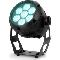
Black and white photo of a Cameroon LED array with 25-lit grid light, no visible text or symbols on the device itself.ZENIT® W600 TW
OUTDOOR LED WASH LIGHT TUNABLE WHITE VERSION CLZW600TW
CONTENTS / INHALTSVERZEICHNIS / CONTENU / CONTENIDO / TREŚĆ / CONTENUTO
ENGLISH
INFORMATION ON THIS USER MANUAL 5
APPROPRIATE USE 5
DEFINITIONS AND SYMBOL EXPLANATIONS 5
SAFETY INSTRUCTIONS 6
NOTES ON PORTABLE OUTDOOR DEVICES 10
INCLUDED 10
INTRODUCTION 10
CONNECTIONS, OPERATING AND DISPLAY ELEMENTS 11
OPERATION 13
SETUP AND INSTALLATION 22
CARE, MAINTENANCE AND REPAIR 23
OPTIONAL ACCESSORIES 25
DMX TECHNOLOGY 26
TECHNICAL DATA 28
EXPLANATION OF IP PROTECTION CLASS 29
MINIMUM DISTANCE TO ILLUMINATED SURFACE 30
MINIMUM DISTANCE TO NORMALLY FLAMMABLE MATERIALS 30
DISPOSAL 30
MANUFACTURER'S DECLARATIONS 30
DEUTSCH
This device has been developed and manufactured to the highest quality standards to ensure many years of problem-free operation. Please read this manual carefully to be able to use your new Cameo product quickly and optimally. Further information about Cameo Light is available on our website CAMEOLIGHT.com.
INFORMATION ON THIS USER MANUAL
- Read the safety instructions and the entire manual carefully before use.
- Observe the warnings on the device and in the user manual.
- Always keep the user manual within reach.
- If you sell or pass on the device, it is important to ensure you pass on this user manual, as it is an integral part of the product.
APPROPRIATE USE
This product is a device for event technology!
The product has been developed for professional use in the field of event technology and is not suitable for use as domestic lighting.
Furthermore, this product is only intended for qualified users with specialist knowledge of event technology!
Use of the product outside the specified technical data and operating conditions is considered inappropriate!
Liability for damage and third-party damage to persons and property due to inappropriate use is excluded!
The product is not suitable for:
- persons (including children) with limited physical, sensory or mental abilities or lack of experience and knowledge.
- children (children must be instructed not to play with the device).
DEFINITIONS AND SYMBOL EXPLANATIONS
- HAZARD: The word HAZARD, possibly in combination with a symbol, indicates situations in which there is an immediate danger or risk of potentially fatal injury.
- WARNING: The word HAZARD, possibly in combination with a symbol, indicates situations in which there is an immediate danger or risk of potentially fatal injury.
- CAUTION: The word CAUTION, possibly in combination with a symbol, indicates situations or conditions that could result in injury.
- ATTENTION: The word ATTENTION, possibly in combination with a symbol, indicates situations or conditions that could result in damage to property and/or the environment.
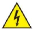
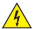
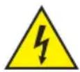
This symbol identifies hazards that can cause electric shock.

This symbol identifies danger points or hazardous situations.
This symbol indicates hazards caused by hot surfaces.
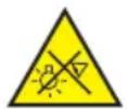
This symbol indicates hazards caused by intense light sources.

This symbol indicates a device in which there are no user-replaceable parts.

This symbol indicates additional information relating to use of the product.
SAFETY INSTRUCTIONS
HAZARD:
- Do not open the device and do not perform any modifications.
- If your device no longer functions properly, if liquids or objects get inside it or if it has been damaged in any other way, switch it off immediately and disconnect it from the mains. The device may be repaired only by authorised repair technicians.
- For devices of protection class 1, the protective conductor must be connected correctly. Never disconnect the protective conductor. Devices of protection class 2 do not have a protective conductor.
- Ensure that live cables are not kinked or otherwise mechanically damaged.
- Never bypass the device fuse.
WARNING:
- The device must not be put into operation if it shows obvious signs of damage.
- The device may only be installed in a voltage-free state.
- If the power cord of the device is damaged, the device must not be used.
- Permanently connected mains cables may only be replaced by a qualified person.
CAUTION:
- Do not put the device into operation immediately if it has been exposed to extreme temperature fluctuations (for example, after transportation). Moisture and condensation can damage the device. Do not switch on the device until it has reached room temperature.
- Ensure that the voltage and frequency of the mains supply match the values specified on the device. If the device has a voltage selector switch, do not connect the device until it has been set correctly. Use only suitable power cables.
- To disconnect the device from the mains on all poles, it is not sufficient to press the on/off switch on the device.
- Make sure that the fuse used corresponds to the type printed on the device.
- Ensure that suitable measures have been taken against overvoltage (e.g. lightning strikes).
- Observe the specified maximum output current on devices with a Power Out connection. Ensure that the total current consumption of all connected devices does not exceed the specified value.
- Replace pluggable mains cables with original cables only.

HAZARD
- Choking hazard! Plastic bags and small parts must be kept out of reach of persons (including children) with reduced physical, sensory or mental capabilities.
- Risk of falling! Make sure that the device is securely installed and will not fall down. Only use suitable stands or mountings (particularly for fixed installations). Make sure that accessories are correctly installed and secured. Ensure that applicable safety regulations are observed.

WARNING:
- Use the device in the prescribed manner only.
- Operate the device using only accessories of the type recommended and supplied by the manufacturer.
- Observe safety regulations applicable in your country during installation.
- After connecting the device, ensure that all cables are routed so as to avoid damage or accidents, such as from tripping.
- Always observe the specified minimum distance to normally flammable materials! Unless explicitly stated, the minimum distance is 0.3 m.
- Always observe the minimum distance to the illuminated surface that can be read on the device!

CAUTION:
- Moving components such as mounting brackets may become jammed.
- In the case of devices with motor-driven components, there is a risk of injury due to the movement of the device. Sudden movement of the device can cause shock reactions.
- The housing surface of the device can become very hot during regular operation. Ensure that accidental touching of the housing is not possible. Always allow the device to cool down sufficiently before removal, maintenance work and charging etc.

CAUTION:
- Do not install or use the device in the vicinity of radiators, accumulators, stoves, or other heat sources Ensure that the device is always installed in such a way that it is sufficiently cooled and cannot overheat.
- Do not place ignition sources, such as burning candles, near the device.
- Ventilation openings must not be covered and fans must not be blocked.
- Use the original packaging or packaging provided by the manufacturer for transport.
- Avoid shocks or impacts to the device.
- Observe the IP rating and the ambient conditions such as temperature and humidity according to the specifications.
- Devices can be further developed on an ongoing basis. In the event of deviating information on operating conditions, performance or other device properties between the user manual and the device labelling, the information on the device always has priority.
- The device is not suitable for tropical climate zones and for operation at over 2000 m above sea level.
- Unless explicitly stated, the device is not suitable for operation under marine conditions.
CAUTION! IMPORTANT INFORMATION REGARDING LIGHTING PRODUCTS!

-
Never look directly into the beam of light, not even for a short period of time.
-
Never look into the beam of light using optical devices such as a magnifying glass.

- Stroboscopic effects may cause epileptic seizures in those susceptible!

- A permanently installed lamp is installed in this lighting unit which must not be replaced by the user. In the event of a fault, please contact your sales partner.

SIGNAL TRANSMISSION BY RADIO (e.g. W-DMX or audio radio systems):
The quality and performance of wireless signal transmissions generally depends on the ambient conditions.
The following factors can impact range and signal stability, for example:
Shielding (e.g. masonry, metal structures, water)
High volume of radio traffic (e.g. powerful wireless LAN networks)
Interference
Electromagnetic radiation (e.g. LED video screens, dimmers)
All range specifications refer to free-field application with visual contact and without interference!
The operation of transmission systems is subject to official regulations. These may vary from region to region and must be checked by the operator before use (e.g. radio frequency and transmission power).

WARNING: Devices with wireless signal transmission are not suitable for use in sensitive areas in which radio operation can lead to potential detrimental effects. These include:
- hospitals, health centres or other healthcare facilities that provide patient treatment with skilled personnel and equipment.
• Hazardous areas Class I, II and III - Restricted areas
- Military facilities
- Aircraft or vehicles
- Areas where the use of mobile phones is prohibited

TRANSMISSION VIA W-DMX
WARNING: In general, wireless DMX transmission must not be used for applications involving safety-related factors that might result in personal injury or property damage in the event of a failure.
This applies in particular to moving scene or traverse structures, DMX-controlled motors/lifts or lifting devices for operating DMX-operated platform lifts, hydraulic systems or comparable moving components.
Furthermore, wireless DMX transmission must not be used to trigger flame or pyrotechnic devices, explosion-driven effects, or to control gas or liquid effects. These include CO2 cannons, confetti shooters, water effects or similar.
NOTES ON PORTABLE OUTDOOR DEVICES

- Temporary operation! Event equipment is generally only designed for temporary operation.
- Continuous operation or permanent structural installation, particularly outdoors, can impair the function, surfaces and seals and accelerate material fatigue.
- Damage to the surface coating can impair the corrosion protection of the device. A damaged surface coating (e.g. scratches) must be promptly restored by means of suitable measures.
INCLUDED
Remove the product from the packaging and remove all packaging material.
Please check the completeness and integrity of the delivery and notify your distribution partner immediately after purchase if the delivery is not complete or if it is damaged.
Product includes:
CLZW600TW Spotlight
Power cable
▶ 2 Omega brackets
▶ User manual
INTRODUCTION
ZENIT W600 PROFESSIONAL OUTDOOR WASHLIGHT TUNABLE WHITE CLZW600TW
CONTROL FUNCTIONS:
1-channel, 2-channel 1, 2-channel 2, 3-channel, 4-channel and 7-channel DMX control, master/slave operation, standalone function DMX ^TM
FEATURES:
40 WW / CW LEDs. IP65 protection rating. DMX512. W-DMX™. 16-bit dimmer. 4 dimmer curves. Adjustable LED PWM frequency. Fast Access Feature. 5-pin DMX connections. Plastic feet. 2 x Omega mounting brackets included. Operating voltage 100-240V AC.25°, 45°, 60° x 10°, 100° diffusers and barndoor optionally available.
The spotlight features the RDM standard (Remote Device Management). Remote device management allows the user to view the status and configuration of RDM terminals via an RDM-capable controller.
CONNECTIONS, OPERATING AND DISPLAY ELEMENTS

text_image
POWER IN 1 3 DMX IN ZENIT® W 600 TW 6 DMX OUT 4 POWER OUT1 POWER IN
IP65 power input socket with rubber sealing cap. Operating voltage 100-240 V AC/50-60 Hz. Connection via supplied power cable (when not in use, always close with rubber sealing cap).
2 POWER OUT
IP65 power output socket with rubber sealing cap. Facilitates power supply to other CAMEO spotlights. Ensure that the total current consumption of all connected devices does not exceed the value specified on the device in amperes (A) (when not in use, always close with the rubber sealing cap).
3 DMX IN
Male IP65 5-pin XLR socket for connecting a DMX control device (e.g. DMX console; when not in use, always close with the rubber sealing cap).
4 DMX OUT
Female IP65 5-pin XLR socket for sending DMX control signal (when not in use, always close with the rubber sealing cap).
5 OLED DISPLAY
The OLED display shows the currently activated mode (main display), the menu items in the selection menu and the numerical value or status in the various menu items.
6 TOUCH-SENSITIVE CONTROLS
MODE
Press MODE to access the main menu. Press again or repeatedly to return to the main display.
ENTER
Select individual menu items in the main menu (DMX address, operating mode etc.) and in the submenus. Allow changes to the status or value in a menu item, such as the DMX address, as required.
UP and DOWN
- Select individual menu items in the main menu (DMX address, operating mode etc.) and in the submenus. Allow changes to the status or value in a menu item, such as the DMX address, as required.
PRESSURE EQUALISATION ELEMENT
The pressure equalisation element to prevent condensation inside the housing is in the device base, behind the cable feed for the LED unit. In order to ensure its proper function, the element must be protected from contamination.
HOUSING FAN
The 3 housing fans and the heat sink are on the back of the LED unit. In order to ensure good air circulation, do not cover the device and clean it regularly.
PLEASE NOTE
- As soon as the spotlight is connected, the following are displayed in succession: "Welcome to Cameo", the model name and the software version. During the start-up process, the previously set operating mode is activated and the spotlight is ready for operation after a short time.
- Before changing the device settings, ensure that the control panel is dry and free of dust in order not to impair its functionality.
-
If one of the DMX operating modes is activated and there is no DMX signal to the DMX input, the currently programmed DMX address is displayed and the characters on the display will begin to flash.
-
Press MODE to go up one level in the menu structure. To go to the main display in the menu structure, press MODE repeatedly.
- The main display is activated automatically if there is no input in the space of approximately one minute.
-
Fast Access Feature: In order to simplify the menu guide, the device has an intelligent menu structure that allows direct access to previously selected menu items and submenu items.
-
Press MODE and ENTER simultaneously for direct access to the last-edited submenu item, where you can make changes instantly as required (DMX starting address and all modes).
- Press MODE to go directly to the last selected and edited menu item. If you now repeatedly press ENTER, you can access the submenu items to make individual settings (DMX start address and all operating modes).
- The display can be rotated through 180^ by pressing UP when the main display is visible.
- To quickly change a value (e.g. DMX start address), press and hold the UP or DOWN button.

CAUTION: In order to provide protection from spraying water, in accordance with protection class IP65, special IP65-rated XLR connectors must be used correctly with the DMX input and output sockets, or they must be closed using the rubber sealing caps. When connected correctly, or when sealed correctly with the rubber sealing caps, the POWER IN and POWER OUT sockets are protected from spraying water, as in accordance with IP65.
OPERATION
MAIN DISPLAY
The main display shows the following information: Current mode (in the example: DMX mode with start address 001) and W-DMX ^TM status.

flowchart
graph TD
    A["W-DMX™ status"] --> B["DMX Address 001"]
    B --> C["Current operating mode"]
W-DMX™
To pair a W-DMX receiver with a W-DMX compatible transmitter
, the Reset command must be executed in the menu item WDMX under Receiver (select Reset and confirm). The receiver is now in pairing standby and waiting for a pairing request from a transmitter. Start the pairing by selecting Link in the menu of the transmitter and confirming; the pairing now takes place automatically. In the same way, several receivers can be paired simultaneously or one after the other to a transmitter (e.g. for master / slave operation). A W-DMX connection is always maintained until the connection is disconnected by means of the Reset command in the receiver or the Unlink command in the transmitter, regardless of whether a device has been disconnected from the power supply in the meantime.
W-DMX™ STATUS
 |  |  | 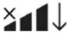 |  |  |  |
| W-DMXTM deactivated | W-DMXTM activated as receiver, not paired | W-DMXTM activated as receiver and is paired to device, Transmitter is switched off or out of range | W-DMX activated and is paired to device, no DMX signal | W-DMXTM activated as receiver and is paired to device, DMX signal is present | W-DMXTM and transmission mode G3 is enabledUp arrow = Send operationDown arrow = Receive operationArrow flashes= Pairing processFlashing stops = Paired | W-DMXTM and transmission mode G4S activatedUp arrow = Send operationDown arrow = Receive operationArrow flashes= Pairing processFlashing stops = Paired |
SETTING DMX START ADDRESS (DMX address)
Press MODE to access the main menu (--- Menu ---). Using UP and DOWN, select the menu item DMX Address (observe arrow) and confirm with ENTER. The display will show a three-digit number field and you can use the UP and DOWN controls to configure the desired DMX start address. Confirm the entry with ENTER and press MODE to return to the main display (in the example, „DMX address 001”).
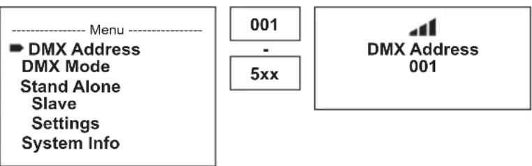
text_image
---- Menu ---- ■ DMX Address DMX Mode Stand Alone Slave Settings System Info 001 - 5xx DMX Address 001CONFIGURING DMX MODE (DMX Mode)
Press MODE to access the main menu (--- Menu ---). Using UP and DOWN, select the menu item DMX Mode (observe arrow) and confirm with ENTER. In the submenu, you can now select the desired DMX mode with UP and DOWN.
Confirm your selection with ENTER. Tables with the channel assignments can be found in these instructions under DMX CONTROL.

text_image
---- Menu ---- DMX Address ► DMX Mode Stand Alone Slave Settings System Info
text_image
---- DMX Mode ---- ► 1CH Mode 2CH Mode 1 2CH Mode 2 3CH Mode 4CH Mode 7CH ModeCONFIGURE STANDALONE MODE
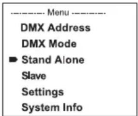
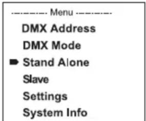
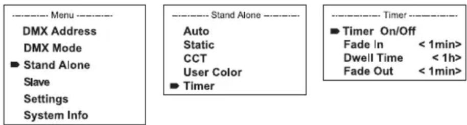
Press MODE to access the main menu (--- Menu ---). Using UP and DOWN, select the menu item Stand Alone (observe arrow) and confirm with ENTER. In the submenu you can now use UP and DOWN to select the standalone modes Auto, Color Macro, Static, Tunable White, User Color, Pixel and the Timer function. Confirm your selection with ENTER.

text_image
---- Menu ---- DMX Address DMX Mode ► Stand Alone Slave Settings System Info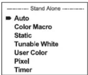
text_image
Stand Alone ▶ Auto Color Macro Static Tunable White User Color Pixel TimerSTANDALONE AUTO MODE (auto program 1-6)
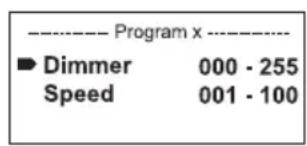
The 6 different auto programs each comprise non-editable colour-change sequences. Brightness and speed are independently adjustable. Press MODE to access the main menu (--- Menu ---). Using UP and DOWN, select the menu item Stand Alone, confirm with ENTER, then select the submenu item Auto and confirm again with ENTER. Now use UP and DOWN to select one of the 6 auto programs (observe arrow) and confirm with ENTER. To adjust brightness, use UP and DOWN to select the menu item Dim and confirm with ENTER, then use UP and DOWN to select the desired value between 000 and 255. Confirm with ENTER. Set the run speed by selecting the menu item Speed, confirm with ENTER, and then select the desired value between 001 and 100. Confirm with ENTER.

text_image
---- Menu ---- DMX Address DMX Mode ► Stand Alone Slave Settings System Info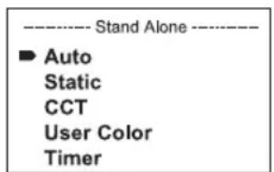
text_image
Stand Alone ▶ Auto Static CCT User Color Timer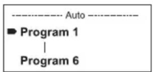
text_image
---- Auto ---- ► Program 1 | Program 6
text_image
---- Program x ---- ► Dimmer 000 - 255 Speed 001 - 100STANDALONE STATIC MODE (Static)
Static mode allows the Dimmer, Strobe and RGBW functions to be adjusted directly on the device with values between 000 to 255, similar to a DMX control unit. In this way, an individual scene can be created without an additional DMX controller. Press MODE to access the main menu (---Menu ---). Using UP and DOWN, select the menu item Stand Alone and confirm with ENTER, then select Static and confirm once again with ENTER. Now use UP and DOWN to select the menu item you wish to edit (observe arrow) and confirm with ENTER. The display will now show a three-digit number field, and you can use UP and DOWN to configure the desired value between 000 and 255. Confirm all entries with ENTER.
text_image
---- Menu ---- DMX Address DMX Mode ► Stand Alone Slave Settings System Info
text_image
Stand Alone Auto Static CCT User Color Timer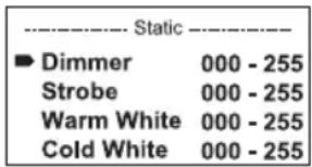
text_image
Static Dimmer 000 - 255 Strobe 000 - 255 Warm White 000 - 255 Cold White 000 - 255STANDALONE MODE CCT
The colour temperature mode enables you to configure the colour temperature from cold white to warm white (CCT) and the brightness (Dim) of the light directly on the device. Press MODE to access the main menu (--- Menu ---). Using UP and DOWN, select the menu item Stand Alone and confirm with ENTER, then select Static and confirm once again with ENTER.Now use UP and DOWN to select the menu item you wish to edit (observe arrow) and confirm with ENTER. The display will show a three-digit number field and you can use the UP and DOWN controls to configure the desired value. Confirm with ENTER.
text_image
---- Menu ---- DMX Address DMX Mode ► Stand Alone Slave Settings System Info
text_image
Stand Alone Auto Static CCT User Color Timer
text_image
Tunable White Dimmer 000 - 255 CCT 2600K - 6500KSTANDALONE MODE USER PRESETS (User Color)
The User Presets operating mode makes it possible to store the overall brightness, strobe and a mixture of warm white and cold white directly in the device in five individual presets. Press MODE to access the main menu (--- Menu ---). Now select the Stand Alone menu item, confirm with ENTER, then select User Color and confirm the entry again with ENTER. Use UP AND DOWN to select one of the stored presets Color1 to Color5 and confirm with ENTER and select the submenu item you want to edit (observe arrow). Confirm with ENTER. The display will show a three-digit number field and you can use the UP and DOWN controls to set the value as required between 000 and 255. Confirm all entries with ENTER.

text_image
---- Menu ---- DMX Address DMX Mode ► Stand Alone Slave Settings System Info ---- Stand Alone ---- Auto Static CCT ► User Color Timer ---- User Color ---- ► Color 1 | Color 5 ---- Color x ---- ► Dimmer 000 - 255 Strobe 000 - 255 Warm White 000 - 255 Cold White 000 - 255TIMER FUNCTION (Timer)
The timer function allows the standalone modes Static, CCT and User Color to be timer controlled in such a way that the fade-in time can be set from 0 to 60 minutes, the dwell time from 1 to 24 hours and the fade-out time from 0 to 60 minutes. The timer starts immediately after activating the timer function in the previously activated standalone mode and remains active even if the spotlight is switched off and restarted. Press MODE to access the main menu (--- Menu ---). Using UP and DOWN, select the menu item Stand Alone and confirm with ENTER, then select Timer and confirm once again with ENTER. For the individual timer control settings, select Fade In, Dwell Time or Fade Out (observe arrow) and confirm with ENTER. The display will show a three-digit number field in each case. Use UP and DOWN to set the value as required from 000 to 060 or 001 to 024. Confirm by pressing ENTER again. Once all settings have been configured as required, activate the timer function by selecting the submenu item Timer On/Off using UP and DOWN, confirm with ENTER, select On and confirm again with ENTER (to deactivate the timer function, please select Off and confirm).
text_image
---- Menu ---- DMX Address DMX Mode ► Stand Alone Slave Settings System Info ---- Stand Alone ---- Auto Static CCT User Color ► Timer ---- Timer ---- ► Timer On/Off Fade In < 1min> Dwell Time < 1h> Fade Out < 1min>Please note: The timer function is suitable for use in master/slave mode via cable and W-DMX ^TM .
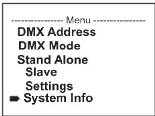
Press MODE to access the main menu (--- Menu ---). Using UP and DOWN, select the menu item Slave (observe arrow) and confirm with ENTER. Connect the slave and the master units (same model, same software version) with a DMX cable and enable a standalone mode on the master unit. The slave unit will now follow the master unit. If there is no control signal, the display characters will flash. Flashing stops as soon as a control signal is present.

text_image
---- Menu ---- DMX Address DMX Mode Stand Alone ► Slave Settings System Info Mode SlaveSYSTEM SETTINGS (Settings)
Press MODE to access the main menu (--- Menu ---). Using UP and DOWN, select the menu item Settings (observe arrow) and confirm with ENTER.

text_image
---- Menu ---- DMX Address DMX Mode Stand Alone Slave ■ Settings System InfoThis will take you to the submenu for setting the following submenu items (see table, select with UP and DOWN, confirm with ENTER, change value or status with UP and DOWN, confirm with ENTER):
| Settings | ||||
| Wireless settingss | = | W-DMX settings (Wireless DMX) | W-DMX On/Off On | = W-DMX activated |
| Off = W-DMX deactivated | ||||
| Operating Mode Re | Receive = W-DMX module as receiver | |||
| Receive = W-DMX module as sender | ||||
| Transmitting Mode | G3 = G3 broadcasting standard | |||
| G4S = G4S transmission standard | ||||
| Link Link = pair with W-DMX units. W-DMX must be activated on all devices and the pairing must be picked up by a transmitter (Receive Reset). | ||||
| Unlink = decoupling of all devices | ||||
| Receive Reset No | = Do not retain transmitter pairing | |||
| Yes = Retain transmitter pairing | ||||
| Display Reverse | = Display rotation On Display is rotated by 180° (e.g. for overhead installation) | |
| Display Back-light | = Display lighting On permanently on | |
| DMX Fail = Operational status with DMX signal fault | Hold Last command is retained | |
| Blackout Activates blackout | ||
| Full On Spotlight switches to full on | ||
| Stand Alone Spotlight switches to standalone mode | ||
| Dimmer Curve | = Dimmer curve Linear | |
| Light intensity increases linearly with DMX value | ||
| Exponential Light intensity can be finely adjusted at lower DMX values and broadly adjusted at higher DMX values | ||
| Logarithmic Light intensity can be broadly adjusted at lower DMX values and finely adjusted at higher DMX values | ||
| S-curve | ||
| Constant Brightness | = Constant brightness when fading from cold white to warm white and vice versa | On |
| Off Function disabled | ||
| Dimmer Response | = Dimmer response LED | Light responds abruptly to changes in DMX value |
| Halogen | ||
| Calibration | = Calibration of warm white and cold white | RAW |
| User Calibration | ||
| Autolock = Automatic locking of the controls | On Automatic locking of the controls after approximately 1 minute of inactivity. Display shown upon attempted use: “Locked!” Unlock: Press and hold UP and DOWN simultaneously for approx. 5 seconds | ||
| Off Automatic locking of the controls is disabled | |||
| PWM Frequency | = LED PWM frequency 650Hz, 1530Hz, 3600Hz, 12000Hz, 18900Hz, 25000Hz | Configuration of LED PWM frequency | |
| Fan = Adjust fan control Auto Automatic fan speed control | |||
| Off Deactivated fan with greatly reduced brightness | |||
| Silent Extra-quiet fan with reduced brightness | |||
| Factory Reset = Reset to factory setting | Reset Now! Reset to factory settings: ENTER -> “Reset Now!” -> ENTER. Press MODE to quit. | ||
Dimmer curves

SYSTEM INFORMATION (System Info)
Press MODE to access the main menu (--- Menu ---). Using the arrow keys, select the menu item System Info (observe arrow) and confirm with ENTER.
text_image
---- Menu ---- DMX Address DMX Mode Stand Alone Slave Settings ■ System InfoUse the UP and DOWN controls to select the desired submenu item, and press ENTER to display the corresponding information.
| System Info | ||||
| Firmware = Displays | Device Firmware | Main CPU | Vx.xx | |
| LED Driver | Vx.xx | |||
| Temperature = Temperature display LED unit | LED xx °C | / xx °F | ||
| Unit °C (= | display in degrees Celsius) | |||
| °F (= display in degrees Fahrenheit) | ||||
| Operation Hours | = Displays operating time | xx:xx h Dis | plays total operating time in hours and minutes | |
MANUAL LOCKING FUNCTION
In addition to the ability to automatically protect the spotlight from accidental and unauthorised operation (see "Settings" - "Auto-lock"), the controls can also be locked manually. Press and hold the UP and DOWN controls simultaneously for approximately 5 seconds. If an attempt is made to change settings, "Locked!" will appear in the display, and changing the spotlight's settings via the controls is no longer possible. After approx. 1 minute, the current operating mode is displayed again. To unlock, press and hold the UP and DOWN controls simultaneously for approximately 5 seconds. The display will show the previously displayed information.
SETUP AND INSTALLATION
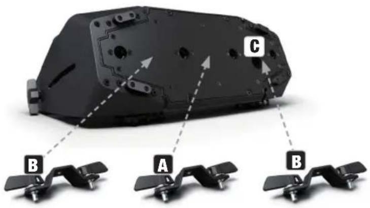
Thanks to its integrated plastic feet, the light can be positioned in a suitable location on a level surface. Mounting to a traverse is possible using an Omega bracket which is attached at the centre of the device base (A) or else by means of two Omega bracket, which are mounted at the outer attachment positions (B). 2 x Omega brackets are included. Suitable beam clamps are available as an option. Ensure firm connections and secure the spotlight to the designated location (C) with a suitable safety cable. The beam direction of the LED unit is set using the wing nuts on the side independently of the device base.

HAZARD: Overhead mounting requires extensive experience, including the calculation of the load limit values of the installation material and regular safety inspection of all installation materials and spotlights. If you do not have these qualifications, do not attempt to perform an installation yourself. Refer instead to a qualified professional.There is a risk that devices that are incorrectly mounted and secured may come loose and fall down. This can cause serious injury or death.
text_image
C B A BCARE, MAINTENANCE AND REPAIR
In order to ensure the long-term, proper functioning of the device, it must be regularly cleaned and, if necessary, maintained. The maintenance requirement depends on the intensity of use and the environment in which it is used.
We generally recommend a visual inspection before each operation. Furthermore, we recommend carrying out all the applicable maintenance measures specified below once every 500 operating hours or, in the case of a lower intensity of use, at the latest after one year. Warranty claims may be limited in the event of defects resulting from inadequate maintenance.
CARE (CARRIED OUT BY USER)
WARNING! Before carrying out any maintenance work, the power supply and, if possible, all device connections must be unplugged.

PLEASE NOTE!!Improper care can lead to impairment of the device or even destruction.
- Housing surfaces must be cleaned with a clean, damp cloth. In doing so, ensure that no moisture can penetrate into the device.
- Air inlets and outlets must be regularly cleaned of dust and dirt. If compressed air is used, care must be taken to ensure that damage to the device is prevented (e.g. fans must be blocked in this case, as they could otherwise over-rev).
- Lines and plug contacts must be cleaned regularly and dust and dirt must be removed.
- In general, no cleaning agents or abrasive agents may be used, otherwise the surface finish may be damaged.
- Devices must generally be stored dry and protected from dust and dirt.
- To ensure correct and safe operation, all accessible or removable lenses and light-emitting apertures must be cleaned regularly.
MAINTENANCE AND REPAIR (by qualified personnel only)

HAZARD! There are live components in the device. Even after disconnecting the mains connection, there may still be residual voltage in the device, e.g. due to charged capacitors.

PLEASE NOTE! There are no user-serviceable components in the device.

PLEASE NOTE! Maintenance and repair work may only be carried out by sufficiently qualified specialist personnel. If in doubt, consult a specialist workshop.

PLEASE NOTE!!Improperly performed maintenance work may affect warranty claims.

PLEASE NOTE! For conversion or retrofit sets provided by the manufacturer, it is essential to observe the installation instructions included.
CLEAN FAN
The three fans on the back of the LED unit of the spotlight must be regularly checked and, if necessary, cleaned. Disconnect the spotlight from the power supply. Loosen the 4 socket screws holding the fan cover to the LED unit using a suitable tool. Remove the fan cover from the LED unit, clean the fans and check that the fans can rotate freely. If compressed air is used, make sure that damage to the device is prevented (e.g. fans must be blocked in this case, as they could otherwise over-rev.). Clean the ventilation openings of the fan cover and reattach the cover using the previously loosened screws. If a fan should block despite cleaning, take the spotlight out of operation and contact an authorised service centre

natural_image
Technical line drawing of a mechanical fan assembly with multiple blades and mounting brackets (no text or symbols)OPTIONAL ACCESSORIES
CLZW6004B
Flap – tool-free mounting thanks to threaded locking bolts, safety cable included

natural_image
Black metal tray device with open lid and attached cable, isolated on white background (no text or symbols)CLZW600SMLSD40
45^ diffuser
Tool-free mounting thanks to SNAPMAG® technology

natural_image
Black rectangular frame with rounded corners on white background (no text or symbols)CLZW600SMLSD6010
60^ × 10^ diffuser
Tool-free mounting thanks to SNAPMAG® technology

natural_image
Black rectangular frame with rounded corners on white background (no text or symbols)
CLZW600SMLSD20
25^ diffuser
Tool-free mounting thanks to SNAPMAG® technology

natural_image
Black rectangular frame with rounded corners on white background (no text or symbols)CLZW600SMLSD100
100° diffuser
Tool-free mounting thanks to SNAPMAG® technology

natural_image
Black rectangular frame with rounded corners on white background (no text or symbols)
natural_image
Black and white photo of a modern optical device with a grid of colored pixels on its side (no text or symbols visible)DMX TECHNOLOGY
DMX-512
DMX (Digital Multiplex) is the name for a universal communication protocol for communication between corresponding devices and controllers. A DMX controller sends DMX data to the attached DMX device(s). The DMX data transmission is always a serial data stream which is sent from one connected device to the next via the DMX
natural_image
Coiled black cable with two connectors and a terminal connector (no text or symbols visible)IN and DMX OUT sockets on any DMX-enabled device (XLR connectors), whereby the maximum number of devices may not exceed 32. The last device in the chain must be equipped with a terminator.
DMX CONNECTION:
DMX is the common “language”, through which a wide variety of equipment types and models from different manufacturers can be connected and controlled via a central controller, as long as all the devices and the controller are DMX-compatible. For optimum data transmission, it is necessary to keep the connection cables between the individual devices as short as possible. The order in which the devices are integrated into the DMX network, has no influence on the addressing. In this way, the device with the DMX address 1 can be placed at any position in the (serial) DMX chain, at the beginning, end, or anywhere in the middle. If a device has been assigned the DMX address 1, the controller “knows” that it must send all the data associated with the address 1 to this device, regardless of its position in the DMX network.
SERIES CONNECTION OF SEVERAL SPOTLIGHTS
- Connect the male XLR connector (3-pin or 5-pin) of the DMX cable to the DMX output (female XLR socket) of the first DMX device (e.g. a DMX controller).
- Connect the female XLR connector of the DMX cable connected to the first spotlight to the DMX input (male XLR socket) of the next DMX device. Connect the DMX output of this device to the DMX input of the next device in the same way and so on. Please note that serial DMX devices can be interconnected in principle and the connections cannot be shared without an active splitter. The maximum number of DMX devices in a DMX chain must not exceed 32.
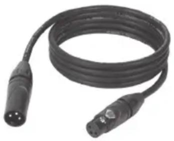
An extensive selection of suitable DMX cables can be found in the Adam Hall product lines 3 STAR, 4 STAR and 5 STAR.
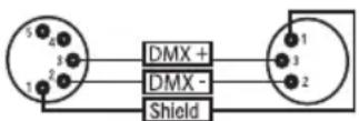
DMX CABLE:
When preparing your own leads, it is essential to follow the diagrams on this page. Do not connect the shielding of the cable to the ground pin of the connector, and make sure that the shield does not come into contact with the XLR connector housing. If the shield has contact to ground it may lead to system errors.
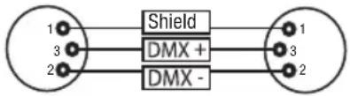
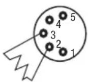
CONNECTOR ASSIGNMENT:
DMX cable with 3-pin XLR connectors: (pins 4 and 5 are not used.)
DMX cable with 5-pin XLR connectors
text_image
1 3 2 Shield DMX + DMX - 1 3 2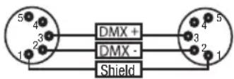
DMX TERMINATOR:
To avoid system failures, the last device in a DMX chain must be equipped with a terminating resistor (120 ohms, 1/4 watt).
3-pin XLR with terminating resistor: K3DMXT3
5-pin XLR with terminating resistor: K3DMXT5
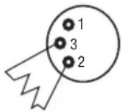
CONNECTOR ASSIGNMENT:
3-pin XLR connector: 5-pin XLR connector:
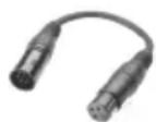
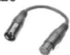
DMX ADAPTER:
The combination of DMX devices with 3-pin connectors and DMX devices with 5-pin ports in a DMX chain is also possible by using adapters.
CONNECTOR ASSIGNMENT
DMX adapter 5-pin male XLR to 3-pin female XLR: K3DGF0020
Pins 4 and 5 are not used.
CONNECTOR ASSIGNMENT
DMX adapter 3-pin male XLR to 5-pin female XLR: K3DHM0020
Pins 4 and 5 are not used.

TECHNICAL DATA
| Product number: CLZW600TW | |
| Product type: LED wash light | |
| Type: Outdoor spotlight | |
| LED colour spectrum: WW + CW (2600K-6500K) | |
| CRI: 93 @ 4000K | |
| Number of LEDs: 40 | |
| LED type: 2-in-1 SMD with collimator lenses | |
| LED output: 12 W | |
| LED PWM frequency: 650 Hz, 1530 Hz, 3600 Hz, 25 kHz (adjustable) | |
| Beam angle: 18° (35° field) | |
| Ports: 5-pin XLR In and Out | |
| DMX mode: 1CH, 2CH-1, 2CH-2, 3CH, 4CH, 7CH Full Access | |
| DMX functions: Dimmer, dimmer fine, strobe, warm white, cold white, colour temperature, system settings | |
| Standalone functions: | Warm white/cold white dimmer, timer, strobe, colour temperature |
| System settings: | Rotate display by 180°, display lighting, DMX fail, dimmer curves, dimmer response, colour calibration, LED PWM frequency, fan control, factory reset |
| Control: | DMX512, W-DMX, RDM |
| Operating controls: | Mode, Enter, Up, Down |
| Display elements: | OLED display |
| Operating voltage: | 100–240 V AC / 50–60 Hz |
| Power supply connection: | TrueCon In + Out (Out max. 6A) |
| Electrical protection class: | 1 |
| Maximum power consumption: | 480 W |
| Luminous flux: | 31,000 lm |
| Ambient temperature (in operation): | -15°C to +40°C |
| Housing material: | Die-cast aluminium |
| Housing colour: | Black |
| Housing cooling: | Fan cooled |
| Protection class: | IP65 |
| Tilt rotation: | 158° (manual) |
| Use position: | As required |
| Minimum distance to illuminated surface: | 0.5 m |
| Minimum distance to normal flammable materials: | 0.5 m |
Dimensions (W x H x D, 463 x 291 x 161 mm. without bracket):
Weight (not including accessories): 11.9 kg
Accessories supplied: 2 Omega brackets + power cable
Optional accessories: Snapmag filter (25°, 45°, 100°, 60°×10°, 90°×10°)
Barn door
EXPLANATION OF IP PROTECTION CLASS
- An IP rating only reflects protection from solid objects and water. It does not describe general weather resistance, such as protection from UV radiation and temperature, etc.
- The first identification digit indicates protection from dust, solid objects and contact:
| IP2X Protected against solid foreign bodies ≥ 12.5 mm in diameter |
| IP3X Protected against solid foreign bodies ≥ 2.5 mm in diameter |
| IP4X Protected against solid foreign bodies ≥ 1.0 mm in diameter |
| IP5X Protected against dust in harmful quantities and completely protected against contact |
| IP6X Are dust-tight and completely protected against contact |
- The second identification digit indicates protection from water:
| IPX0 no | protection |
| IPX1 | Protection against dripping water |
| IPX2 | Protection against dripping water when the device is tilted up to 15° |
| IPX3 | Protection against falling spray water up to 60° from the vertical |
| IPX4 | Protection against splashing water on all sides |
| IPX5 | Protection against water jets (nozzle) from any angle |
| IPX6 | Protection against strong water jets |
| IPX7 | Protection against temporary immersion |
- In addition, some device-specific measures such as covers and sealing caps are necessary in order to achieve the specified protection class (e.g. protective caps on unused connections).

The IP rating of the product can be found in the technical data and is printed on the device.
MINIMUM DISTANCE TO ILLUMINATED SURFACE
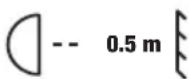
This symbol with distance information in metres (m) indicates the minimum distance of the luminaire to the illuminated surface. In this example, the distance is 0.5 m. The value valid for this unit can be found in the technical data in this manual and on the print on the unit housing!
MINIMUM DISTANCE TO NORMALLY FLAMMABLE MATERIALS
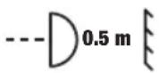
This symbol with distance information in metres (m) indicates the minimum distance of the unit to normally flammable materials. In this example, the distance is 0.5 m. For the value valid for this unit, please refer to the technical data in these instructions!
DISPOSAL

PACKAGING:
- Packaging can be fed into the reusable material cycle using the usual disposal methods.
- Please separate the packaging in accordance with the disposal laws and recycling regulations in your country.
DEVICE:
- This device is subject to the European Directive on Waste Electrical and Electronic Equipment, as amended. WEEE Directive Waste Electrical and Electronic Equipment. Old appliances do not belong in household waste. The old device must be disposed of via an approved disposal company or a municipal disposal facility. Please observe the applicable regulations in your country!
- Observe all disposal laws applicable in your country.
- As a private customer, you can obtain information on environmentally-friendly disposal options from the seller of the product or the appropriate regional authorities.
MANUFACTURER'S DECLARATIONS
MANUFACTURER'S WARRANTY & LIMITATION OF LIABILITY
Adam Hall GmbH, Adam-Hall-Str. 1, D-61267 Neu Anspach / E-mail Info@adamhall.com / +49 (0)6081 / 9419-0.
Our current warranty conditions and limitation of liability can be found at:
https://cdn-shop.adamhall.com/media/pdf/Manufacturers-Declarations-CAMEO_DE_EN_ES_FR.pdf.
Contact your sales partner for service.
UKCA- CONFORMITY
Hereby, Adam Hall Ltd. declares that this product meets the following guidelines (where applicable)
Electrical Equipment (Safety) Regulations 2016
Electromagnetic Compatibility Regulations 2016 (SI 2016/1091)
The Restriction of the Use of Certain Hazardous Substances in Electrical and Electronic Equipment Regulation 2012 (SI 2012/3032)
Radio Equipment Regulations 201 7(SI 2016/2015)
UKCA- DECLARATION OF CONFORMITY
Products that are subject to Electrical Equipment(Safety)Regulation 2016, EMC Regulation 2016 or RoHS Regulation can be requested at info@adamhall.com.
Products that are subject to the Radio Equipments Regulations 2017 (SI2017/1206) can be downloaded from www.adamhall.com/compliance/
SUBJECT TO MISPRINTS AND ERRORS, AS WELL AS TECHNICAL OR OTHER MODIFICATIONS!
DEUTSCH
text_image
Stand Alone ▶ Auto Static CCT User Color Timer
flowchart
graph TD
    A["Program 1"] --> B["Program 6"]
    style A fill:#f9f,stroke:#333
    style B fill:#ccf,stroke:#333
    note right of A: Auto
text_image
---- Program x ---- ► Dimmer 000 - 255 Speed 001 - 100STAND-ALONE-BETRIEBSART STATISCHER MODUS (STATIC)
text_image
User Color Color 1 | Color 5
text_image
Color x Dimmer 000 - 255 Strobe 000 - 255 Warm White 000 - 255 Cold White 000 - 255TIMER-FUNKTION (TIMER)
text_image
Timer ▶ Timer On/Off Fade In < 1min> Dwell Time < 1h> Fade Out < 1min>natural_image
Technical line drawing of a mechanical fan assembly with multiple blades and mounting brackets (no text or symbols)OPTIONALES ZUBEHÖR
CLZW6004B
natural_image
Black metal tray device with open lid and attached cable, isolated on white background (no text or symbols)CLZW600SMLSD40
45^ Streuscheibe
natural_image
Black rectangular frame with rounded corners on white background (no text or symbols)CLZW600SMLSD6010
60^ × 10^ Streuscheibe
natural_image
Black rectangular frame with rounded corners on white background (no text or symbols)
CLZW600SMLSD20
25° Streuscheibe
natural_image
Black rectangular frame with rounded corners on white background (no text or symbols)CLZW600SMLSD100
100° Streuscheibe
natural_image
Black rectangular frame with rounded corners on white background (no text or symbols)
natural_image
Black and white photo of a handheld electronic device with a grid of glowing pink beads, no visible text or symbols.DMX TECHNIK
DMX-512
natural_image
Coiled black cable with two connectors and a three-pin connector (no text or symbols visible)DMX-Adapter 5-Pol XLR male auf 3-Pol XLR female: K3DGF0020
https://cdn-shop.adamhall.com/media/pdf/Manufacturers-Declarations-CAMEO_DE_EN_ES_FR.pdf.
text_image
Stand Alone ▶ Auto Static CCT User Color Timer
text_image
Auto Program 1 | Program 6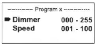
text_image
---- Program x ---- ► Dimmer 000 - 255 Speed 001 - 100MODE DE FONCTIONNEMENT STANDALONE / MODE STATIQUE (Static)
text_image
User Color Color 1 | Color 5
text_image
Color x Dimmer 000 - 255 Strobe 000 - 255 Warm White 000 - 255 Cold White 000 - 255FONCTION DE TEMPORISATION (Timer)
text_image
Timer ▶ Timer On/Off Fade In < 1min> Dwell Time < 1h> Fade Out < 1min>natural_image
3D diagram of a mechanical component with labeled parts A, B, and C, showing internal structure and alignment (no text or symbols beyond labels)ENTRETIEN, MAINTENANCE ET RÉPARATION
natural_image
Technical line drawing of a mechanical fan assembly with multiple blades and mounting brackets (no text or symbols)ACCESSOIRES DISPONIBLES EN OPTION
CLZW6004B
natural_image
Black plastic enclosure with open lid and attached cable, isolated on white background (no text or symbols)CLZW600SMLSD40
Diffuseur 45°
natural_image
Black rectangular frame with rounded corners on white background (no text or symbols)CLZW600SMLSD6010
Diffuseur 60° x 10°
natural_image
Black rectangular frame with rounded corners on white background (no text or symbols)
CLZW600SMLSD20
Diffuseur 25°
natural_image
Black rectangular frame with rounded corners on white background (no text or symbols)CLZW600SMLSD100
Diffuseur 100°
natural_image
Black rectangular frame with rounded corners on white background (no text or symbols)
natural_image
Black and white photo of a handheld electronic device with a grid of glowing pink beads, no visible text or symbols.TECHNOLOGIE DMX
DMX-512
natural_image
Coiled black cable with two connectors (no text or symbols visible)RACCORDEMENT DMX :
https://cdn-shop.adamhall.com/media/pdf/Manufacturers-Declarations-CAMEO_DE_EN_ES_FR.pdf.
Directive CEM (2014/30/UE)
RoHS (2011/65/UE)
RED (2014/53/UE)
DÉCLARATION DE CONFORMITÉ CE
text_image
Stand Alone ▶ Auto Static CCT User Color Timer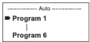
text_image
---- Auto ---- ► Program 1 | Program 6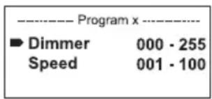
text_image
---- Program x ---- ► Dimmer 000 - 255 Speed 001 - 100MODO OPERATIVO AUTÓNOMO «MODO ESTÁTICO» (Static)
text_image
User Color Color 1 | Color 5
text_image
Color x Dimmer 000 - 255 Strobe 000 - 255 Warm White 000 - 255 Cold White 000 - 255text_image
Timer ▶ Timer On/Off Fade In < 1min> Dwell Time < 1h> Fade Out < 1min>natural_image
3D diagram of a mechanical component with labeled parts A, B, and C, showing internal structure and alignment indicators (no text or symbols beyond labels)natural_image
Technical line drawing of a mechanical fan assembly with multiple blades and mounting brackets (no text or symbols)natural_image
Black rectangular electronic device with open lid and cable, isolated on white background (no text or symbols)CLZW600SMLSD40
Difusor de 45°
natural_image
Black rectangular frame with rounded corners on white background (no text or symbols)CLZW600SMLSD6010
Difusor de 60° x 10°
natural_image
Black rectangular frame with rounded corners on white background (no text or symbols)
CLZW600SMLSD20
Difusor de 25°
natural_image
Black rectangular frame with rounded corners on white background (no text or symbols)CLZW600SMLSD100
Difusor de 100°
natural_image
Black rectangular frame with rounded corners on white background (no text or symbols)
natural_image
Black and white photo of a handheld electronic device with a grid of glowing pink beads, no visible text or symbols.TECNOLOGÍA DMX
DMX-512
natural_image
Coiled black cable with two connectors and a terminal connector (no text or symbols visible)https://cdn-shop.adamhall.com/media/pdf/Manufacturers-Declarations-CAMEO_DE_EN_ES_FR.pdf.
TRANSMISJA SYGNAŁÓW W W-DMX
text_image
Stand Alone ▶ Auto Static CCT User Color Timer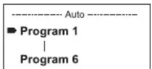
text_image
---- Auto ---- ► Program 1 | Program 6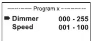
text_image
---- Program x ---- ► Dimmer 000 - 255 Speed 001 - 100TRYB PRACY STANDALONE „STATYCZNY” (Static)
USTAWIENIA WSTĘPNE UŻYTKOWNIKA (User Color)
text_image
User Color Color 1 | Color 5
text_image
Color x Dimmer 000 - 255 Strobe 000 - 255 Warm White 000 - 255 Cold White 000 - 255FUNKCJA TIMERA (Timer)
text_image
Timer ▶ Timer On/Off Fade In < 1min> Dwell Time < 1h> Fade Out < 1min>natural_image
3D diagram of a mechanical component with labeled parts A, B, and C, showing internal structure and alignment indicators (no text or symbols beyond labels)CZYSZCZENIE, KONSERWACJA I NAPRAWY
natural_image
Technical line drawing of a car air conditioning unit with multiple fans and cooling fins (no text or labels)OPCJONALNE AKCESORIA
CLZW6004B
natural_image
Black open electrical enclosure with attached wires, no visible text or symbolsCLZW600SMLSD40
Dyfuzor 45^
natural_image
Black rectangular frame with rounded corners on white background (no text or symbols)CLZW600SMLSD6010
Dyfuzor 60^ × 10^
natural_image
Black rectangular frame with rounded corners on white background (no text or symbols)
CLZW600SMLSD20
Dyfuzor 25^
natural_image
Black rectangular frame with rounded corners on white background (no text or symbols)CLZW600SMLSD100
Dyfuzor 100^
natural_image
Black rectangular frame with rounded corners on white background (no text or symbols)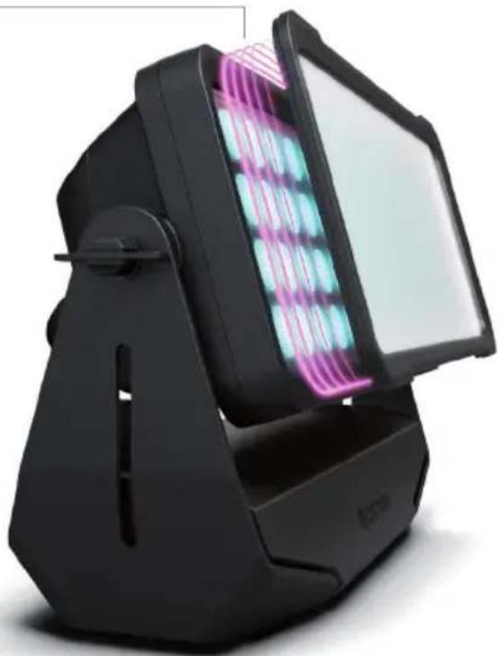
natural_image
Black and white photo of a modern electronic device with a grid of glowing pink and cyan modules (no visible text or symbols)TECHNIKA DMX
DMX-512
natural_image
Coiled black cable with two connectors and a terminal connector (no text or symbols visible)https://cdn-shop.adamhall.com/media/pdf/Manufacturers-Declarations-CAMEO_DE_EN_ES_FR.pdf.
text_image
Stand Alone ▶ Auto Static CCT User Color Timer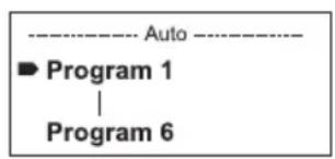
text_image
Auto Program 1 | Program 6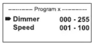
text_image
---- Program x ---- ► Dimmer 000 - 255 Speed 001 - 100MODALITÀ DI FUNZIONAMENTO STAND-ALONE, MODALITÀ STATICA (Static)
text_image
User Color Color 1 | Color 5
text_image
Color x Dimmer 000 - 255 Strobe 000 - 255 Warm White 000 - 255 Cold White 000 - 255FUNZIONE TIMER (Timer)
text_image
Timer ▶ Timer On/Off Fade In < 1min> Dwell Time < 1h> Fade Out < 1min>natural_image
Technical line drawing of a mechanical fan assembly with multiple blades and mounting brackets (no text or symbols)ACCESSORI OPZIONALI
CLZW6004B
natural_image
Black plastic electronic device with open lid and cable attachment (no text or symbols visible)CLZW600SMLSD40
Diffusore da 45°
natural_image
Black rectangular frame with rounded corners on white background (no text or symbols)CLZW600SMLSD6010
natural_image
Black rectangular frame with rounded corners on white background (no text or symbols)
CLZW600SMLSD20
Diffusore da 25°
natural_image
Black rectangular frame with rounded corners on white background (no text or symbols)CLZW600SMLSD100
Diffusore da 100°
natural_image
Black rectangular frame with rounded corners on white background (no text or symbols)
natural_image
Black and white photo of a modern digital display unit with a grid of glowing pink beads (no text or symbols visible)TECNOLOGIA DMX
DMX-512
natural_image
Coiled black cable with two connectors and a three-pin connector (no text or symbols visible)COLLEGAMENTO DMX:
https://cdn-shop.adamhall.com/media/pdf/Manufacturers-Declarations-CAMEO_DE_EN_ES_FR.pdf.
| 1CH Mode | ||||||
| Ch. Function Values Sub-Group | ||||||
| 1 Dimmer 000 - 255 | 0% to 100% (preselection Stand Alone -> CCT value required) | Intensity | ||||
| 2CH Mode 1 | ||||||
| Ch. | Function Values | Sub-Group | ||||
| 1 | Dimmer 000 - 255 | 0% to | 10 | 0% Intensity | ||
| 2 | Color Temperature | 000 - | 04 | 6 Warm | white -> 2700K | CCT |
| 047 - | 04 | 7 Bulb White (2700K) | ||||
| 048 - | 08 | 7 2700K | -> 3200K | |||
| 088 - | 08 | 8 Halogen | White (3200K) | |||
| 089 - | 12 | 8 3200K | -> 4000K | |||
| 129 - | 12 | 9 Neutral | White (4000K) | |||
| 130 - | 16 | 9 4000K | -> 5600K | |||
| 170 - | 17 | 0 Studio | -White (5600K) | |||
| 171 - | 21 | 0 5600K | -> 6500K | |||
| 211 - | 21 | 1 Daylight | White (6500K) | |||
| 212 - | 25 | 4 6500K | -> cold Daylight | |||
| 255 - | 25 | 5 Cold Daylight | ||||
| 2CH Mode 2 | |||||
| Ch. Function Values Sub-Group | |||||
| 1 Warm White 000 - | 255 0% to 100% Intensity | ||||
| 2 Cold White | 000 - 005 | 0% to100% | Intensity | ||
| 3CH Mode | |||||
| Ch. | Function Values | Sub-Group | |||
| 1 | Dimmer 0 - 255 0 | % to 100% | Intensity | ||
| 2 | Strobe functions | 000 - 005 Strobe open | Multifunctional Strobe | ||
| 006 - 010 Strobe closed | |||||
| 011 - 033 Pulse random, slow -> fast | |||||
| 034 - 056 Ramp up random, slow -> fast | |||||
| 057 - 079 Ramp down random, slow -> fast | |||||
| 080 - 102 Random Strobe effect, slow -> fast | |||||
| 103 - 127 | Strobe Break effect, 5s.....1s (short burst with break) | ||||
| 128 - 250 Strobe slow -> fast <1Hz - 20Hz | |||||
| 251 - 255 Strobe open | |||||
| 3 | Color Temperature | 000 - 046 Warm white -> 2700K | CCT | ||
| 047 - 047 Bulb White (2700K) | |||||
| 048 - 087 2700K -> 3200K | |||||
| 088 - 088 Halogen White (3200K) | |||||
| 089 - 128 3200K -> 4000K | |||||
| 129 - 129 Neutral White (4000K) | |||||
| 130 - 169 4000K -> 5600K | |||||
| 170 - 170 Studio-White (5600K) | |||||
| 171 - 210 5600K -> 6500K | |||||
| 211 - 211 Daylight White (6500K) | |||||
| 212 - 254 6500K -> cold Daylight | |||||
| 255 - 255 Cold Daylight | |||||
| 4CH Mode | ||||||
| Ch. Function Values Sub-Group | ||||||
| 1 | Dimmer | 000 | - | 255 | 0% to 100% | Intensity |
| 2 Strobe functions | 000 | - | 005 | Strobe open | Multifunctional Strobe | |
| 006 | - | 010 | Strobe closed | |||
| 011 | - | 033 | Pulse random, slow -> fast | |||
| 034 | - | 056 | Ramp up random, slow -> fast | |||
| 057 | - | 079 | Ramp down random, slow -> fast | |||
| 080 | - | 102 | Random Strobe effect, slow -> fast | |||
| 103 | - | 127 | Strobe Break effect, 5s.....1s (Short burst with break) | |||
| 128 | - | 250 | Strobe slow -> fast <1Hz - 20Hz | |||
| 251 | - | 255 | Strobe open | |||
| 3 | Warm White | 000 | - | 255 | 0% to 100% | Intensity |
| 4 | Cold White | 000 | - | 255 | 0% to 100% | Intensity |
| 7CH Mode | ||||||
| Ch. | Function Values | Sub-Group | ||||
| 1 | Dimmer 000 - 255 | 0% to | 10 | 0% Inte | sity | |
| 2 | Dimmer fine 000 | 255 | 0% to | 100% | Intensity | |
| 3 | Strobe func-tions | 000 | 00 | 5 Strobe | open | Multifunctio-nal Strobe |
| 006 | 01 | 0 Strobe | closed | |||
| 011 | 03 | 3 Pulse | random, slow -> fast | |||
| 034 | 05 | 6 Ramp | up random, slow -> fast | |||
| 057 | 07 | 9 Ramp | down random, slow -> fast | |||
| 080 | 10 | 2 Random | Strobe effect, slow -> fast | |||
| 103 | 12 | 7 | Strobe Break effect, 5s.....1s (Short burst with break) | |||
| 128 | 25 | 0 Strobe | slow -> fast <1Hz - 20Hz | |||
| 251 | 25 | 5 Strobe | open | |||
| 4 | Warm White 000 | 255 | 0% to | 100% | Intensity | |
| 5 | Cold White | 000 | - | 255 | 0% to100% | Intensity |
| 6 | Color Tempera-ture (overrides Warm White + Cold White Channel) | 000 | 00 | 5 off | CCT | |
| 006 | 00 | 6 Warm | white | |||
| 007 | 04 | 6 Warm | white -> 2700K | |||
| 047 | 04 | 7 Bulb White (2700K) | ||||
| 048 | 08 | 7 2700K | -> 3200K | |||
| 088 | 08 | 8 Halogen | White (3200K) | |||
| 089 | 12 | 8 3200K | -> 4000K | |||
| 129 | 12 | 9 Neutral | White (4000K) | |||
| 130 | 16 | 9 4000K | -> 5600K | |||
| 170 | 17 | Studio | -White (5600K) | |||
| 171 | 21 | 0 5600K | -> 6500K | |||
| 211 | 21 | 1 Daylight | White (6500K) | |||
| 212 | 25 | 4 6500K | -> cold Daylight | |||
| 255 | 25 | 5 Cold Daylight | ||||
| 7 Device settings | 000 - 073 No function | Control | ||
| 074 - 075 Dimmer Response LED (hold 1,5 s) | ||||
| 076 - 077 Dimmer Response Halogen (hold 1,5 s) | ||||
| 078 - 097 No function | ||||
| 098 - 099 Auto Fan (hold 3s) | ||||
| 100 - 101 Fan Off (hold 3s) | ||||
| 102 - 103 Silent Fan (hold 1,5s) | ||||
| 104 - 119 No function | ||||
| 120 - 121 PWM 1 (650 Hz) (hold 3s) | ||||
| 122 - 123 PWM 2 (1530 Hz) (hold 3s) | ||||
| 124 - 125 PWM 3 (3600 Hz) (hold 3s) | ||||
| 126 - 127 PWM 4 (12000 Hz) (hold 3s) | ||||
| 128 - 129 PWM 5 (18900 Hz) (hold 3s) | ||||
| 130 - 131 PWM 6 (25000 Hz) (hold 3s) | ||||
| 132 - 133 RAW (hold 3s) | ||||
| 134 - 135 No function | ||||
| 136 - 137 User Calibrated (hold 3s) | ||||
| 138 - 139 No function | ||||
| 140 - 141 Display on (hold 3s) | ||||
| 142 - 143 Display off (hold 3s) | ||||
| 144 - 163 No function | ||||
| 164 - 165 Dimmer Curve Linear (hold 3s) | ||||
| 166 - 167 Dimmer Curve exp (hold 3s) | ||||
| 168 - 169 Dimmer Curve log (hold 3s) | ||||
| 170 - 171 Dimmer Curve S-Curve (hold 3s) | ||||
| 172 - 173 | CCT fade constant brightness on (hold 3s) | |||
| 174 - 175 | CCT fade constant brightness off (hold 3s) | |||
| 176 - 255 No function | ||||