
LZR210 - Detector BLACK & DECKER - Free user manual and instructions
Find the device manual for free LZR210 BLACK & DECKER in PDF.
| Product Type | Multifunction laser detector (laser level, stud finder, metal and live wire detector) |
| Brand | Black & Decker |
| Model | LZR210 |
| Power Source | 1x 9V battery (type 6LR61) |
| Weight | 0.45 kg |
| Operating Temperature | 0°C to 40°C |
| Laser | Class 2, wavelength 630-675 nm, power < 2.2 mW |
| Laser Level Function | Projects horizontal/vertical laser lines for alignment |
| Stud Finder Function | Detects wood and metal studs behind drywall up to 18 mm thick |
| Metal Detector Function | Detects metal pipes behind drywall up to 18 mm |
| Live Wire Detector Function | Detects AC cables up to 38 mm depth (230 V~) |
| Included Accessories | Marking/hanging insert, keyhole accessory, spacer insert, wall cleat |
| Care and Cleaning | Clean with a dry cloth; do not use solvents |
| Safety | Do not look directly into the laser beam; do not use in presence of flammable liquids; keep out of reach of children |
| Warranty | 2 years (subject to conditions in the manual) |
| Repairability | Repairs by authorized technician only; battery replaceable by user |
Frequently Asked Questions - LZR210 BLACK & DECKER
User questions about LZR210 BLACK & DECKER
0 question about this device. Answer the ones you know or ask your own.
Ask a new question about this device
Download the instructions for your Detector in PDF format for free! Find your manual LZR210 - BLACK & DECKER and take your electronic device back in hand. On this page are published all the documents necessary for the use of your device. LZR210 by BLACK & DECKER.
USER MANUAL LZR210 BLACK & DECKER
natural_image
Illustration of a person adjusting a wall-mounted device with a remote control unit (no text or symbols)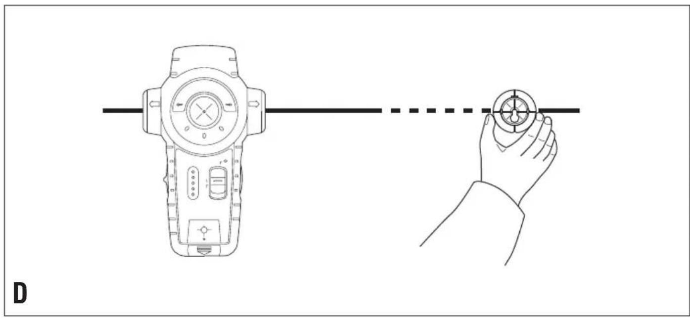
natural_image
Line drawing showing a handheld device connected to a hand holding a circular component, with no text or symbols present.E
natural_image
Illustration showing two scenarios of a person using a handheld device to interact with a wall-mounted sensor (no text or symbols present)F
natural_image
Illustration of hands holding a camera on a wall-mounted device, with a grid pattern and an arrow indicating motion (no text or symbols)ENGLISH
Intended use
This Black & Decker tool has been designed to project laser lines to aid in DIY applications, and to help locating wooden studs, live wires operating at mains voltage (230 V_AC ) and metal pipes covered by wall boards. This tool is intended for consumer use only.
Safety instructions
◆Warning! When using battery-powered tools, basic safety precautions, including the following, should always be followed to reduce the risk of fire, leaking batteries, personal injury and material damage.
◆Read all of this manual carefully before operating the tool.
◆Retain this manual for future reference.
Keep work area clean
Cluttered areas and benches can cause accidents.
Consider work area environment
Do not expose the tool to rain. Do not use the tool in damp or wet conditions. Keep the work area well lit. Do not use the tool where there is a risk of causing fire or explosion, e.g. in the presence of flammable liquids and gases.
Keep children away
Do not allow children, visitors or animals to come near the work area or to touch the tool.
Do not overreach
Keep proper footing and balance at all times.
Stay alert
Watch what you are doing. Use common sense. Do not operate the tool when you are tired.
Use appropriate tool
The intended use is described in this instruction manual.
Warning! The use of any accessory or attachment or performance of any operation with this tool other than those recommended in this instruction manual may present a risk of personal injury.
Check for damaged parts
Before use, carefully check the tool for damage. Ensure that the tool will operate properly and perform its intended function. Do not use the tool if any part is damaged or defective.
Store idle tools
When not in use, tools and batteries should be stored in a dry, locked up or high place, out of reach of children.
Repairs
This tool complies with relevant safety requirements. Repairs should only be carried out by qualified persons using original spare parts; otherwise this may result in considerable danger to the user.
Additional safety instructions for non-rechargeable batteries
◆Never attempt to open for any reason.
◆Do not store in locations where the temperature may exceed 40 °C.
- When disposing of batteries, follow the instructions given in the section "Protecting the environment". Do not incinerate the batteries.
◆Under extreme conditions, battery leakage may occur. When you notice liquid on the batteries, proceed as follows: - Carefully wipe the liquid off using a cloth. Avoid skin contact.
Additional safety instructions for lasers

Warning! Laser radiation.

Do not look into the laser beam.

Do not view the laser beam directly with optical instruments.
Refer to the laser product characteristics.
◆This laser complies with class 2 according to EN 60825-1:1994+A1+A2. Do not replace a laser diode with a different type. If damaged, have the laser repaired by an authorised repair agent.
◆Do not use the laser for any purpose other than projecting laser lines.
◆An exposure of the eye to the beam of a class 2 laser is considered safe for a maximum of 0.25 seconds.
Eyelid reflexes will normally provide adequate protection.
At distances over 1 m, the laser complies with class 1 and thus is considered completely safe.
◆Never look into the laser beam directly and intentionally.
◆Do not use optical tools to view the laser beam.
◆Do not set up the tool at a position where the laser beam can cross any person at head height.
◆Do not let children come near the laser.
Additional safety instructions for pipe and wire detectors
◆Do not use the tool to detect AC voltage in uninsulated, exposed or free wires.
◆Do not use the tool as a substitute for a voltmeter.
◆Be aware that the tool may not always properly detect all pipes and wires. The following conditions can cause inaccurate results:
- Low battery
- Thick walls with thin pipes or wires
- Very thick walls
- Very deep wires or pipes
- Walls covered with metal
- Very humid conditions
- Shielded cables
◆Before use, always test the tool by detecting a known pipe or wire.
◆If in doubt contact a qualified contractor.
Warning! This tool will not detect wires in circuits isolated from the mains supply, cables operating at direct current (DC) or wires used for telecommunication or computer systems. Hidden wires (e.g. wall lights) may not be detected when switches are in the off position.
Warning! This tool will not detect pipes of any other material than metal.
Features
- On/off switch (laser)
- On/off switch (stud/metal finder)
- Mode selector switch
- LED indicators (stud/metal finder)
- LED indicator (wire detector)
- Insert holder
- Marking/hanging insert
- Keyhole insert
- Spacer insert
- Drywall pin
- Laser apertures
Assembly
Fitting the battery (fig. A)
◆Depress the release button and remove the battery cover (12) from the tool.
◆Connect the battery to the connector. The larger battery terminal connects to the smaller connector terminal.
◆Refit the cover and let it click into place.
Fitting and removing inserts
The marking/hanging insert (7) is used to make a mark on the level line or to hang the tool on a drywall board using the drywall pin (10) supplied. The keyhole insert (8) is used to hang the tool on other types of wall using a screw or nail. The spacer insert (9) is used to extend the laser line.
Fitting
◆Place the insert into the holder from the back of the tool.
♦Align the notches on the insert with the recesses in the insert holder (6).
◆Let the insert click into place.
Removing
◆Keep the notches on the insert depressed.
◆Push the insert out of the holder.
Use
Using the laser level function (fig. B)
◆Place the tool flat against the wall as shown.
◆Push the on/off switch (1) up to switch the tool on.
◆Move the tool as necessary to position the laser lines.
◆If necessary, hang the unit on the wall using the appropriate insert.
Note: the laser lines will only be level if the tool is kept within 5° from vertical.
◆Push the on/off switch (1) down to switch the tool off.
Using the spacer insert (fig. C)
If you need to extend the laser line, use the spacer insert (9) as shown.
Note: the stud sensor cannot be used with the spacer insert fitted.
Enhancing the visibility of the beam (fig. D)
If because of the lighting conditions it is difficult to see the laser line, you can use one of the inserts as shown to enhance the line.
Selecting the operating mode
◆Set the mode selector switch (3) to the 'STUD' position for the detection of wooden studs.
◆Set the mode selector switch (3) to the 'METAL' position for the detection of metal studs, pipes, etc.
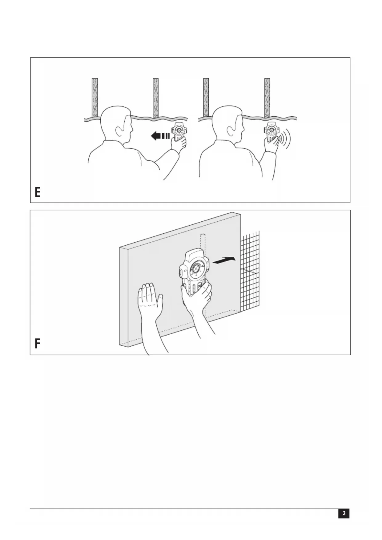
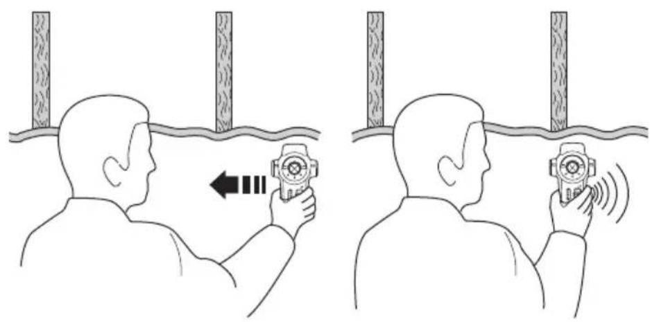
Using the stud finder function (fig. E)
You can use this function to find wooden and metal studs through drywall boards up to 18 mm thick.
◆Fit the marking insert (7).
◆Set the mode selector switch (3) to the required position.
◆Place the tool flat against the wall as shown.
◆Keep the on/off switch (2) depressed.
The red LED indicator (4) will light up and the buzzer will sound once while the tool is calibrating. After calibration is completed:
- Slowly slide the tool in a horizontal direction. Make sure not to tilt or lift the tool.
When the red LED indicator (4) lights up, slow down and slide the tool further until the buzzer sounds and the top green LED indicator is on.
This position indicates the one edge of the stud.
◆Mark this position through the hole in the marking insert (7).
◆Move the unit further until the LED indicators are off.
◆While still keeping the on/off switch (2) depressed, move the tool in the opposite direction.
ENGLISH
- When the red LED indicator (4) lights up, slow down and slide the tool further until the buzzer sounds and the top green LED indicator is on.
This position indicates the other edge of the stud.
◆Mark this position through the hole in the marking insert (7).
The centre of the stud is between the two marks.
Using the metal finder function (fig. E)
You can use this function to find metal pipes through drywall boards up to 18 mm thick.
◆Fit the marking insert (7).
◆Set the mode selector switch (3) to the 'METAL' position.
◆Place the tool flat against the wall as shown.
◆Keep the on/off switch (2) depressed.
The red LED indicator (4) will light up and the buzzer will sound once while the tool is calibrating. After calibration is completed:
◆While holding the unit with one hand place your other hand on the surface close to the area being scanned.
◆Move the tool slowly and smoothly across the surface, approaching from different directions.
When the red LED indicator (4) lights up, slow down and slide the tool further until the buzzer sounds and the top green LED indicator is on.
This position indicates the location of a metal object.
◆After detecting the work area repeat the testing procedure to confirm the operation of the unit.
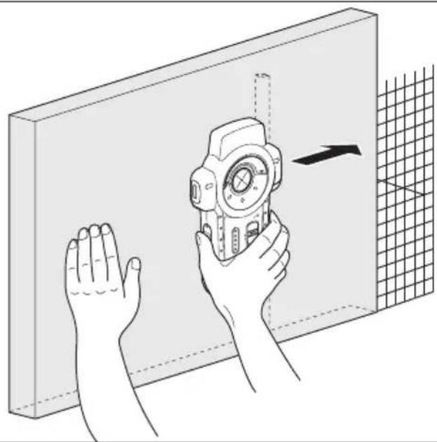
Using the wire detector function (fig. F)
You can use this function to find live wires through drywall boards up to 38 mm thick. The function works continuously in all modes.
Warning! Test the unit on a known AC current before use.
Make sure the unit is away from the area being scanned and any other AC current source. Static charge may interfere detection on both sides of the wire, resulting in limited accuracy.
◆Keep the on/off switch (2) depressed.
The red LED indicator (4) will light up and the buzzer will sound once while the tool is calibrating. After calibration is completed:
◆While holding the unit with one hand place your other hand on the surface close to the area being scanned.
◆Move the tool slowly and smoothly across the surface, approaching from different directions.
When an AC source is located, the red LED indicator (5) will blink.
◆After detecting the work area repeat the testing procedure to confirm the operation of the unit.
Protecting the environment

Separate collection. This product must not be disposed of with normal household waste.
Should you find one day that your Black & Decker product needs replacement, or if it is of no further use to you, do not dispose of it with household waste. Make this product available for separate collection.

Separate collection of used products and packaging allows materials to be recycled and used again. Re-use of recycled materials helps prevent environmental pollution and reduces the demand for raw materials.
Local regulations may provide for separate collection of electrical products from the household, at municipal waste sites or by the retailer when you purchase a new product.
Black & Decker provides a facility for the collection and recycling of Black & Decker products once they have reached the end of their working life. To take advantage of this service please return your product to any authorised repair agent who will collect them on our behalf.
You can check the location of your nearest authorised repair agent by contacting your local Black & Decker office at the address indicated in this manual. Alternatively, a list of authorised Black & Decker repair agents and full details of our after-sales service and contacts are available on the Internet at: www.2helpU.com
Battery

At the end of their useful life, discard batteries with due care for our environment.
◆Remove the battery as described above.
◆Place the battery in a suitable packaging to ensure that the terminals cannot be short-circuited.
◆Take the battery to a local recycling station.
Technical data
LZR210
Voltage V 9
Battery size 6LR61
Operating temperature °C 0 - 40
Wave length nm 630-675
Laser class 2
Laser power mW < 2.2
Weight kg 0.45
EC declaration of conformity
LZR210
Black & Decker declares that these products conform to:
89/336/EEC, EN 61010, EN 60825

Kevin Hewitt
Director of Consumer Engineering
Spennymoor, County Durham DL16 6JG,
United Kingdom
1-12-2004
Guarantee
Black & Decker is confident of the quality of its products and offers an outstanding guarantee. This guarantee statement is in addition to and in no way prejudices your statutory rights. The guarantee is valid within the territories of the Member States of the European Union and the European Free Trade Area.
If a Black & Decker product becomes defective due to faulty materials, workmanship or lack of conformity, within 24 months from the date of purchase, Black & Decker guarantees to replace defective parts, repair products subjected to fair wear and tear or replace such products to ensure minimum inconvenience to the customer unless:
◆The product has been used for trade, professional or hire purposes;
◆The product has been subjected to misuse or neglect;
◆The product has sustained damage through foreign objects, substances or accidents;
◆Repairs have been attempted by persons other than authorised repair agents or Black & Decker service staff.
To claim on the guarantee, you will need to submit proof of purchase to the seller or an authorised repair agent. You can check the location of your nearest authorised repair agent by contacting your local Black & Decker office at the address indicated in this manual. Alternatively, a list of authorised Black & Decker repair agents and full details of our after-sales service and contacts are available on the Internet at:
www.2helpU.com
Please visit our website www.blackanddecker.co.uk to register your new Black & Decker product and to be kept up to date on new products and special offers. Further information on the Black & Decker brand and our range of products is available at www.blackanddecker.co.uk
DEUTSCH
Director of Consumer Engineering
Spennymoor, County Durham DL16 6JG,
United Kingdom
1-12-2004
Garantie
Spennymoor, County Durham DL16 6JG,
Royaume-Uni
1-12-2004
Garantie
Spennymoor, County Durham DL16 6JG,
United Kingdom
1-12-2004
Garanzia
Director of Consumer Engineering
Spennymoor, County Durham DL16 6JG,
United Kingdom
1-12-2004
Garantie
Spennymoor, County Durham DL16 6JG,
United Kingdom
1-12-2004
Garantía
Spennymoor, County Durham DL16 6JG,
United Kingdom
1-12-2004
Garantia
Director of Consumer Engineering
Spennymoor, County Durham DL16 6JG,
United Kingdom
1-12-2004
Reservdelar / reparationer
Director of Consumer Engineering
Spennymoor, County Durham DL16 6JG,
United Kingdom
1-12-2004
Director of Consumer Engineering
Spennymoor, County Durham DL16 6JG,
United Kingdom
1-12-2004
Reservedele / reparationer
Director of Consumer Engineering
Spennymoor, County Durham DL16 6JG,
United Kingdom
1-12-2004
Spennymoor, County Durham DL16 6JG,
United Kingdom
1-12-2004
Εγγύηση
• This is a key decision for the following: (1) if you are not able to know what you can find this
◆ Data protection act: Tick the box if you prefer

Cat. no.:
◆ Δικυμον αντροσμου
revendor - Artificialis layers address
The Ground Truth image displays a single, solid horizontal line. According to Rule 2 (UNDERSCORE & LINE RULES), this is a stylistic or background line, not a placeholder underscore. Therefore, the OCR result must ignore it and output nothing or only meaningful text. The provided OCR content is "____", which consists of four underscores. This is an incorrect interpretation of the line as a placeholder, violating the rule that stylistic lines must be ignored. The OCR has hallucinated underscores where none should exist based on the GT's visual context. Hence, the OCR result is inconsistent with the Ground Truth.
N N N . N N
◆ Sim ◆ Ja ◆ Ja ◆ Ja ◆ Ja ◆ Ja ◆ Ja ◆ Ja ◆ Ja ◆ Ja ◆ Ja ◆ Ja ◆ Ja ◆ Ja ◆ Ja ◆ Ja ◆ Ja ◆ Ja ◆ Ja ◆ Ja ◆ Ja ◆ Ja ◆ Ja ◆ Ja ◆ Ja ◆ Ja ◆ Ja ◆ Ja ◆ Ja ◆ Ja ◆ Ja ◆ Ja ◆ Ja ◆ Ja ◆ Ja
■ Yes Ja Qui Si Ja ▲ Si
nquim oq avoq?
konesei? ◆ Eival to epoxyrio auto in

Aizulevan avtrapocou Hlucopniva aypods
Dealer addresses Date of purchase
Handelardeesse Kaufatum
The image contains a single, solid horizontal line, which is a stylistic or background element (like a rule line on paper). According to Rule 2, such lines must be ignored by the OCR result. Therefore, the corrected OCR text is:
[Empty]
No Nein Non No Need
No N _a0
□
◆ Is this tool your first purchase? ◆ Ist diseases
English Please complete this section immediately after the purchase of your
tool and send it to Black & Decker in your country. If you live in Australia or New Zealand, please register by using the alternative
guarantee card supplied.
Black & Decker in uw land.
