
PHKS 750 A1 - Electric saw PARKSIDE - Free user manual and instructions
Find the device manual for free PHKS 750 A1 PARKSIDE in PDF.
| Product type | Electric circular saw |
| Brand | PARKSIDE |
| Model | PHKS 750 A1 |
| Power supply | 230 V~, 50 Hz (mains plug) |
| Rated power | 750 W |
| No-load speed | 5,000 min⁻¹ |
| Max. cutting depth | 45 mm (at 0°), 31 mm (at 45°) |
| Blade diameter | 140 mm |
| Blade bore | 20 mm |
| Blade tooth thickness | 1.5 mm |
| Protection class | II (double insulation) |
| Sound pressure level (LpA) | 89.1 dB(A) (uncertainty 3 dB) |
| Sound power level (LWA) | 97.1 dB(A) (uncertainty 3 dB) |
| Vibrations (main handle) | 2.774 m/s² (uncertainty 1.5 m/s²) |
| Approximate weight | 3.5 kg |
| Included accessories | TCT blade 12 teeth, hex key 5 mm, flat wrench 17 mm, parallel guide, dust extraction adapter, instruction manual |
| Warranty | 3 years |
| Main functions | Continuous cutting angle adjustment (0-45°), depth adjustment, auto-return lower guard, dust extraction connection, spindle lock for blade change |
| Maintenance | Regular cleaning with dry cloth, check guard and blade, no user-specific maintenance |
Frequently Asked Questions - PHKS 750 A1 PARKSIDE
User questions about PHKS 750 A1 PARKSIDE
0 question about this device. Answer the ones you know or ask your own.
Ask a new question about this device
Download the instructions for your Electric saw in PDF format for free! Find your manual PHKS 750 A1 - PARKSIDE and take your electronic device back in hand. On this page are published all the documents necessary for the use of your device. PHKS 750 A1 by PARKSIDE.
USER MANUAL PHKS 750 A1 PARKSIDE
PDF ONLINE
parkside-diy.com
HANDKREISSÄGE/CIRCULAR SAW/SCIE CIRCULAIRE PHKS 750 A1
DE AT CH
HANDKREISSÄGE
Bedienungsanleitung
Translation of the original instructions
FR BE
SCIE CIRCULAIRE
Mode d'emploi
| DE/AT/CH | Bedienungsanleitung | Seite | 5 | |
| GB/IE | User manual Page 26 | |||
| FR/BE | Mode d’emploi Page 43 | |||
| NL/BE | Gebruiksaanwijzing | Pagina | 64 | |
| PL | Instrukcja obsługi Strona 83 | |||
| CZ | Návod na obsluhu Strana 103 | |||
| SK | Návod na obsluhu Strana 121 | |||
| ES | Manual de instrucciones | Página 139 | ||
| DK | Betjeningsvejledning | Side 158 | ||
| IT | Istruzioni per l’uso | Pagina 176 | ||
| HU | Használati útmutató | Oldal 195 |
22 Schraubenschlüssel
23 Parallelanschlag
24 Adapter
(Abb. C)
16a Spindel
16b Innerer Flansch
(Abb. E)
7a Haltebügel
Technische Daten
List of pictograms used ...... Page 27
Introduction ...... Page 28
Intended use.... Page 28
Scope of delivery Page 28
Parts description.... Page 29
Technical data.... Page 29
Safety instructions ...... Page 30
General power tool safety warnings.... Page 30
Vibration and noise reduction.... Page 32
Behaviour in emergency situations. Page 33
Residual risks Page 33
Safety instructions for circular saws. Page 33
Further safety instructions for all saws.... Page 34
Lower guard function ...... Page 34
Additional safety warnings Page 35
Safety information for the saw blade .... Page 35
Before first use.... Page 36
Unpacking the product.... Page 36
Accessories Page 36
Preparation...... Page 36
Checking the function of the lower guard .... Page 36
Installing/changing the saw blade .... Page 36
Connecting to dust extraction Page 37
Mounting the parallel fence Page 38
Adjusting the cutting angle.... Page 38
Adjusting the cutting depth ...... Page 38
Switching on/off Page 38
Work instructions Page 38
Cleaning and care Page 39
Cleaning Page 39
Maintenance.... Page 39
Repair Page 39
Storage Page 40
Transportation.... Page 40
Disposal Page 40
Warranty.... Page 40
Warranty claim procedure. Page 41
Service Page 41
EU Declaration of conformity.... Page 42
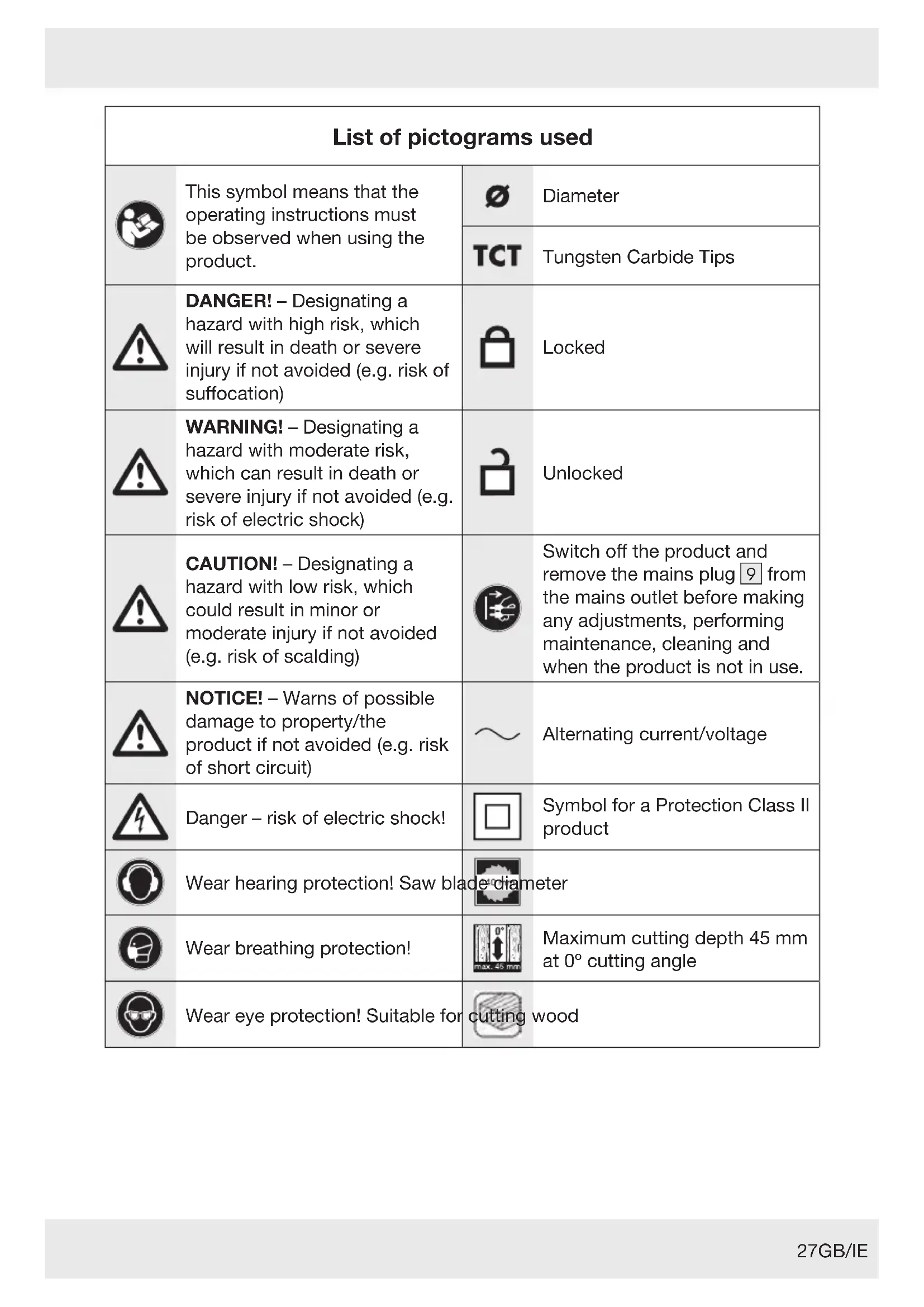
| List of pictograms used | |||
 | This symbol means that the operating instructions must be observed when using the product. | [842H] | Diameter |
| TCT | Tungsten Carbide Tips | ||
 | DANGER! - Designating a hazard with high risk, which will result in death or severe injury if not avoided (e.g. risk of suffocation) |  | Locked |
 | WARNING! - Designating a hazard with moderate risk, which can result in death or severe injury if not avoided (e.g. risk of electric shock) |  | Unlocked |
 | CAUTION! - Designating a hazard with low risk, which could result in minor or moderate injury if not avoided (e.g. risk of scalding) |  | Switch off the product and remove the mains plug 9 from the mains outlet before making any adjustments, performing maintenance, cleaning and when the product is not in use. |
 | NOTICE! - Warns of possible damage to property/the product if not avoided (e.g. risk of short circuit) | ~ | Alternating current/voltage |
 | Danger - risk of electric shock! |  | Symbol for a Protection Class II product |
 | Wear hearing protection! Saw blac  meter meter | ||
 | Wear breathing protection! |  | Maximum cutting depth 45 mm at 0° cutting angle |
 | Wear eye protection! Suitable for c  wood wood | ||
 | Wear protective gloves! |  | Rotational direction arrow marked on saw blade 15 |
 | Do not touch saw teeth. |  | Rotational direction arrow marked on upper guard 19 |
 | Do not use any damaged saw blade. |  | Safety information Instructions for use |
 | CE mark indicates conformity with relevant EU directives applicable for this product. | ||
CIRCULAR SAW
- Introduction
We congratulate you on the purchase of your new product. You have chosen a high quality product. The instructions for use are part of the product. They contain important information concerning safety, use and disposal. Before using the product, please familiarise yourself with all of the safety information and instructions for use. Only use the product as described and for the specified applications. If you pass the product on to anyone else, please ensure that you also pass on all the documentation with it.
Intended use
This circular saw (hereinafter "product" or "power tool") is suitable for sawing the following materials:
- nature wood
- plywood
-
chipboard
– similar light weight construction materials -
Cutting in wet condition and cutting metal are prohibited.
■ Any other use or modification of the product are considered improper use and can result in hazards such as
death, life-threatening injuries and damage.
The manufacturer is not liable for any damages caused by improper use.
The product is exclusively intended for domestic use.
The product is not intended for commercial use, industrial operations or similar purposes.
- Observe all applicable local safety regulations, standards and ordinances. The use of noise emitting power tools may be restricted to certain times by national or local regulations.
- Scope of delivery
WARNING!
The product and the packaging are not children's toys! Children must not play with plastic bags, sheets and small parts! There is a danger of choking and suffocation!
After unpacking the product, check if the delivery is complete and if all parts are in good condition. Remove all packaging materials before use.
1 Circular Saw
1 TCT saw blade
(12 teeth, pre-installed)
1 Hex key (5 mm)
1 Spanner (17 mm)
1 Parallel fence
1 Adaptor
1 User manual
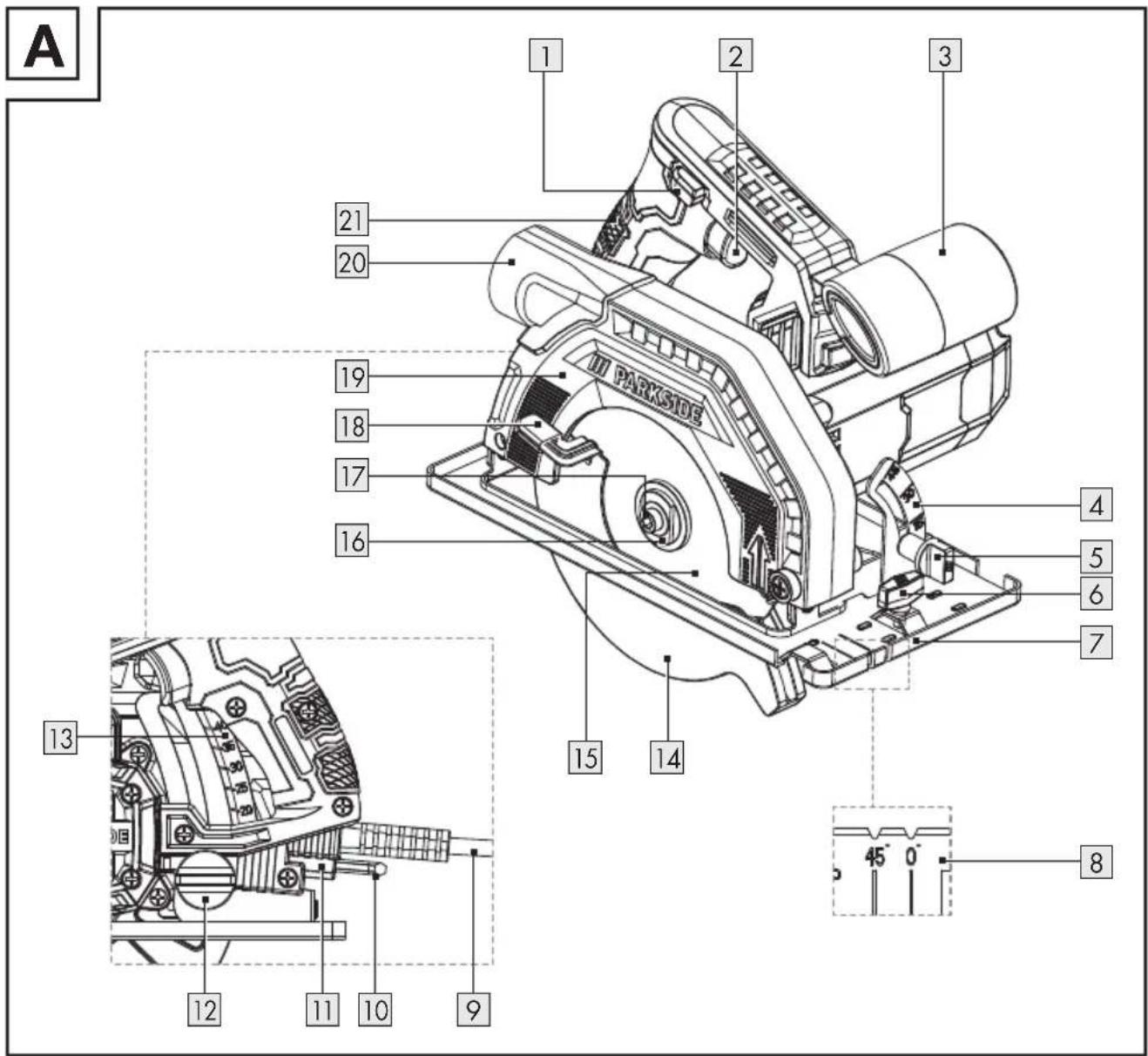
Parts description
(Fig. A)
| 1 | Switch lock |
| 2 | On/off switch |
| 3 | Auxiliary handle |
| 4 | Cutting angle scale |
| 5 | Wing screw for cutting angle preselection |
| 6 | Wing screw (parallel fence) |
| 7 | Base plate |
| 8 | Cutting guide (0° and 45°) |
| 9 | Mains cord with mains plug |
| 10 | Hex key |
| 11 | Hex key storage |
| 12 | Wing screw (cutting depth scale) |
| 13 | Cutting depth scale (0 to 45 mm) |
| 14 | Lower guard |
| 15 | Saw blade |
| 16 | Outer flange |
| 17 | Clamping screw (with washer) |
| 18 | Lever (lower guard) |
| 19 | Upper guard |
| 20 | Dust port |
| 21 | Main handle |
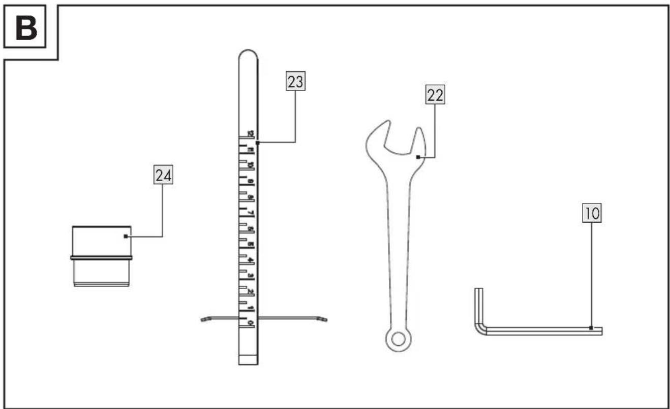
(Fig. B)
| 22 | Spanner |
| 23 | Parallel fence |
| 24 | Adaptor |
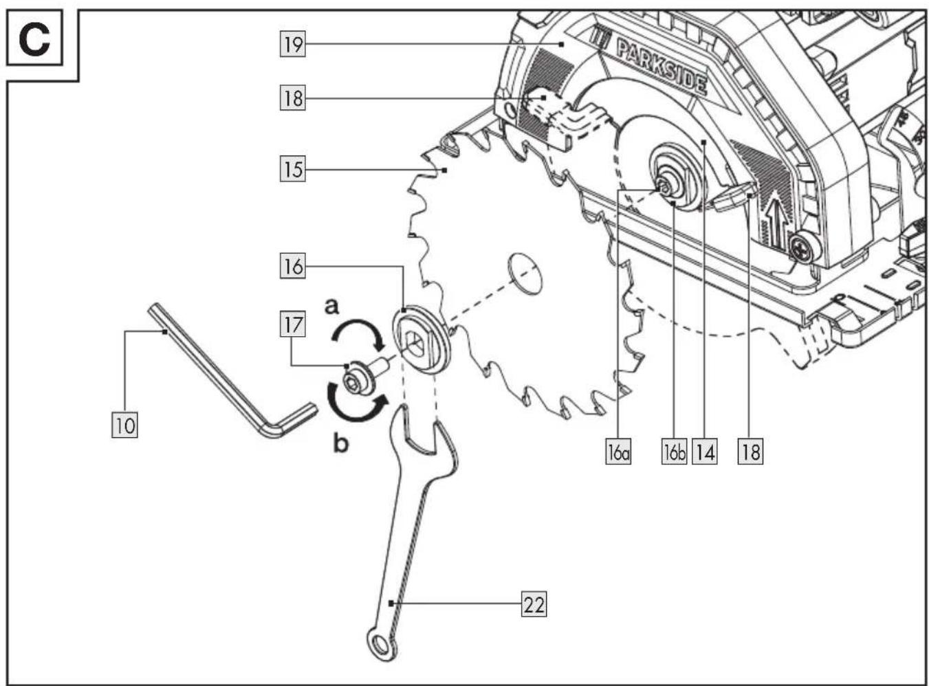
(Fig. C)
| 16a | Spindle |
| 16b | Inner flange |
(Fig. E)
| 7a | Holding bracket |
- Technical data
| Circular Saw PHKS | 750 A1 |
| Model number:– with VDE plug: HG11714– with BS plug: HG11714-BS | |
| Rated input voltage: 230 V~, 50 Hz | |
| Nominal output: 750 W | |
| Idle speed n0: 5,000 min-1 | |
| Max. cutting depth:– at 0°: approx. 45 mm– at 45°: approx. 31 mm | |
| Thread size: | M6 |
| Protection class: | II/☐(double insulation) |
Saw blade dimensions
| Model number: - 12 teeth: | HG11768 |
| Diameter: | ∅ 140 mm |
| Bore size: | ∅ 20 mm |
| Teeth thickness: | 1.5 mm |
| Allowable rotational speed: | max. 9,500 min ^-1 |
Noise emission value
Noise measurement value determined in accordance with EN 62841. The A-rated noise level of the power tool at the working location is typically as follows:
| Sound pressure level L_pA : | 89.1 dB |
| Uncertainty K_pA : | 3 dB |
| Sound power level L_WA : | 97.1 dB |
| Uncertainty K_WA : | 3 dB |

WARNING!

Wear hearing protection!
Vibration emission value
Vibration value ( a_h ) when sawing in wood:
| Main handle: 2.774 m/s | 2 |
| Uncertainty K: 1.5 m/s | 2 |
| Auxiliary handle: 2.816 m/s | 2 |
| Uncertainty K: 1.5 m/s | 2 |

WARNING!
Depending on the manner in which the power tool is being used and, in particular, the kind of workpiece being worked, the vibration and noise emission values can deviate from the values given in these instructions during actual use of the power tool.
It is necessary to establish safety measures to protect the operator based on an estimation of the vibration load during actual use (wherein all states of operation must be included, e.g. times when the power tool is switched off and times where the power tool is switched on but running without load).
NOTE
The vibration emission values and the noise emission values given in these instructions have been measured in accordance with a standardised test procedure and can be used for comparison of the power tool with another tool.
NOTE
The specified total vibration values and the noise emission values can also be used to make a provisional load estimate.

Safety instructions
● General power tool safety warnings

WARNING!
Read all safety warnings, instructions, illustrations and specifications provided with this power tool. Failure to follow all instructions listed below may result in electric shock, fire and/or serious injury.
Save all warnings and instructions for future reference.
The term “power tool” in the warnings refers to your mains-operated (corded) power tool or battery-operated (cordless) power tool.
Work area safety
a) Keep work area clean and well lit. Cluttered or dark areas invite accidents.
b) Do not operate power tools in explosive atmospheres, such as in the presence of flammable liquids, gases or dust. Power tools create sparks which may ignite the dust or fumes.
c) Keep children and bystanders away while operating a power tool. Distractions can cause you to lose control.
Electrical safety
a) Power tool plugs must match the outlet. Never modify the plug in any way. Do not use any adapter plugs with earthed (grounded) power tools. Unmodified plugs and matching outlets will reduce risk of electric shock.
b) Avoid body contact with earthed or grounded surfaces, such as pipes, radiators, ranges and refrigerators. There is an increased risk of electric shock if your body is earthed or grounded.
c) Do not expose power tools to rain or wet conditions. Water entering a power tool will increase the risk of electric shock.
d) Do not abuse the cord. Never use the cord for carrying, pulling or unplugging the power tool. Keep cord away from heat, oil, sharp edges or moving parts. Damaged or entangled cords increase the risk of electric shock.
e) When operating a power tool outdoors, use an extension cord suitable for outdoor use. Use of a cord suitable for outdoor use reduces the risk of electric shock.
f) If operating a power tool in a damp location is unavoidable, use a residual current device (RCD) protected supply. Use of an RCD reduces the risk of electric shock.
Personal safety
a) Stay alert, watch what you are doing and use common sense when operating a power tool. Do not use a power tool while you are tired or under the influence of drugs, alcohol or medication. A moment of inattention while operating power tools may result in serious personal injury.
b) Use personal protective equipment. Always wear eye protection. Protective equipment such as dust mask, non-skid safety shoes, hard hat, or hearing protection used for appropriate conditions will reduce personal injuries.
c) Prevent unintentional starting. Ensure the switch is in the off-position before connecting to power source and/or battery pack, picking up or carrying the tool. Carrying power tools with your finger on the switch or energising power tools that have the switch on invites accidents.
d) Remove any adjusting key or wrench before turning the power tool on. A wrench or a key left attached to a rotating part of the power tool may result in personal injury.
e) Do not overreach. Keep proper footing and balance at all times. This enables better control of the power tool in unexpected situations.
f) Dress properly. Do not wear loose clothing or jewellery. Keep your hair, clothing and gloves away from moving parts. Loose clothes, jewellery or long hair can be caught in moving parts.
g) If devices are provided for the connection of dust extraction and collection facilities, ensure these are connected and properly used. Use of dust collection can reduce dust-related hazards.
h) Do not let familiarity gained from frequent use of tools allow you to become complacent and ignore tool safety principles. A careless action can cause severe injury within a fraction of a second.
Power tool use and care
a) Do not force the power tool. Use the correct power tool for your application. The correct power tool will do the job better and safer at the rate for which it was designed.
b) Do not use the power tool if the switch does not turn it on and off. Any power tool that cannot be controlled with the switch is dangerous and must be repaired.
c) Disconnect the plug from the power source and/or the battery pack, if detachable, from the power tool before making any adjustments, changing accessories, or storing power tools. Such preventive safety measures reduce the risk of starting the power tool accidentally.
d) Store idle power tools out of the reach of children and do not allow persons unfamiliar with the power tool or these instructions to operate the power tool. Power tools are dangerous in the hands of untrained users.
e) Maintain power tools and accessories. Check for misalignment or binding of moving parts, breakage of parts and any other condition that may affect the power tool's operation. If damaged, have the power tool repaired before use. Many accidents are caused by poorly maintained power tools.
f) Keep cutting tools sharp and clean. Properly maintained cutting tools with sharp cutting edges are less likely to bind and are easier to control.
g) Use the power tool, accessories and tool bits etc. in accordance with these instructions, taking into account the working
conditions and the work to be performed. Use of the power tool for operations different from those intended could result in a hazardous situation.
h) Keep handles and grasping surfaces dry, clean and free from oil and grease. Slippery handles and grasping surfaces do not allow for safe handling and control of the tool in unexpected situations.
Service
a) Have your power tool serviced by a qualified repair person using only identical replacement parts. This will ensure that the safety of the power tool is maintained.
● Vibration and noise reduction
To reduce the impact of noise and vibration emission, limit the time of operation, use low-vibration and low-noise operating modes as well as wear personal protective equipment.
Take the following points into account to minimise the vibration and noise exposure risks:
■ Only use the product as intended by its design and these instructions.
■ Ensure that the product is in good condition and well maintained.
■ Use correct accessory tools for the product and ensure they are in good condition.
- Keep tight grip on the handles/grip surface.
- Maintain this product in accordance with these instructions and keep it well lubricated (where appropriate).
■ Plan your work schedule to spread any high vibration tool use across a longer period of time.
● Behaviour in emergency situations
Familiarise yourself with the use of this product by means of this instruction manual. Memorise the safety warnings and follow them to the letter. This will help to prevent risks and hazards.
■ Always be alert when using this product, so that you can recognise and handle risks early. Fast intervention can prevent serious injury and damage to property.
■ Switch the product off and disconnect it from the mains if there are malfunctions. Have the product checked by a qualified professional and repaired, if necessary, before you operate it again.
- Residual risks
Even if you are operating this product in accordance with all the safety requirements, potential risks of injury and damage remain. The following dangers can arise in connection with the structure and design of this product:
■ Health defects resulting from vibration emission if the product is being used over long periods of time or not adequately managed and properly maintained.
Injuries and damage to property due to broken accessory tools or the sudden impact of hidden objects during use.
■ Danger of injury and property damage caused by flying objects.
● Safety instructions for circular saws
Sawing method
a)

Danger! Keep hands away from cutting area and the blade. If both
hands are holding the saw, they
cannot be cut by the blade.
b) Do not reach underneath the workpiece. The guard cannot protect you from the blade below the workpiece.
c) Adjust the cutting depth to the thickness of the workpiece. Less than a full tooth of the blade teeth should be visible below the workpiece.
d) Never hold the workpiece in your hands or across your leg while cutting. Secure the workpiece to a stable platform. It is important to support the work properly to minimise body exposure, blade binding, or loss of control.
e) Hold the power tool by insulated gripping surfaces, when performing an operation where the cutting tool may contact hidden wiring or its own cord.
Contact with a “live” wire will also make exposed metal parts of the power tool “live” and could give the operator an electric shock.
f) When ripping always use a rip fence or straight edge guide.
This improves the accuracy of cut and reduces the chance of blade binding.
g) Always use blades with correct size and shape (diamond versus round) of arbour holes. Blades that do not match the mounting hardware of the saw will run off-centre, causing loss of control.
h) Never use damaged or incorrect blade washers or bolt. The blade washers and bolt were specially designed for your saw, for optimum performance and safety of operation.
● Further safety instructions for all saws
Kickback – causes and related warnings
- A kickback is a sudden reaction to a pinched, jammed or misaligned saw blade, causing an uncontrolled saw to lift up and out of the workpiece toward the operator;
- when the blade is pinched or jammed tightly by the kerf closing down, the blade stalls and the motor reaction drives the unit rapidly back toward the operator;
- if the blade becomes twisted or misaligned in the cut, the teeth at the back edge of the blade can dig into the top surface of the wood causing the blade to climb out of the kerf and jump back toward the operator.
Kickback is the result of saw misuse and/or incorrect operating procedures or conditions and can be avoided by taking proper precautions as given below.
a) Maintain a firm grip on the saw and position your arms to resist kickback forces. Position your body to either side of the blade, but not in line with the blade. Kickback could cause the saw to jump backwards, but kickback forces can be controlled by the operator, if proper precautions are taken.
b) When blade is binding, or when interrupting a cut for any reason, release the trigger and hold the saw motionless in the material until the blade comes to a complete stop. Never attempt to remove the saw from the work or pull the saw backward while the blade is in motion or kickback may occur. Investigate and take corrective actions to eliminate the cause of blade binding.
c) When restarting a saw in the workpiece, centre the saw blade in the kerf so that the saw teeth are not engaged into the material. If a saw blade binds, it may walk up or kickback from the workpiece as the saw is restarted.
d) Support large panels to minimise the risk of blade pinching and kickback. Large panels tend to sag under their own weight. Supports must be placed under the panel on both sides, near the line of cut and near the edge of the panel.
e) Do not use dull or damaged blades. Unsharpened or improperly set blades produce narrow kerf causing excessive friction, blade binding and kickback.
f) Blade depth and bevel adjusting locking levers must be tight and secure before making the cut. If blade adjustment shifts while cutting, it may cause binding and kickback.
g) Use extra caution when sawing into existing walls or other blind areas. The protruding blade may cut objects that can cause kickback.
● Lower guard function
a) Check the lower guard for proper closing before each use. Do not operate the saw if the lower guard does not move freely and close instantly. Never clamp or tie the lower guard into the open position. If the saw is accidentally dropped, the lower guard may be bent. Raise the lower guard with the retracting handle and make sure it moves freely and does not touch the blade or any other part, in all angles and depths of cut.
b) Check the operation of the lower guard spring. If the guard and the spring are not operating properly, they must be serviced before use. Lower guard may operate sluggishly due to damaged parts, gummy deposits, or a build-up of debris.
c) The lower guard may be retracted manually only for special cuts such as “plunge cuts” and “compound cuts”. Raise the lower guard by the retracting handle and as soon as the blade enters the material, the lower guard must be released. For all other sawing, the lower guard should operate automatically.
d) Always observe that the lower guard is covering the blade before placing the saw down on bench or floor. An unprotected, coasting blade will cause the saw to walk backwards, cutting whatever is in its path. Be aware of the time it takes for the blade to stop after switch is released.
Additional safety warnings
a) Do not allow the ejected cutting chip come into contact with your hands. You may be injured or cut by high-speed saw chip.
b) Do not use the saw above the level of your head. Doing so will mean you have inadequate control of the power tool.
c) Do not use grinding discs with this tool. It will be broken easily and cause personal injury.
d) Use suitable detectors to determine if utility lines are hidden in the work area or call the local utility company for assistance. Contact with electric lines can lead to fire and electric
shock. Damaging a gas line can lead to explosion. Penetrating a water line causes property damage or may cause an electric shock.
e) Do not modify and operate the power tool as stationary tool. It is not suitable for operation as a table saw.
f) Secure the workpiece. A
workpiece clamped with clamping
devices or in a vice is held more
secure than by hand.
g) Do not use HSS (High Speed Steel) saw blades. Such saw blades can easily break and jam into wood during cutting works.
h) Do not saw any ferrous metals. Hot chips may ignite the plastic parts of the tool. Metal cutting dust goes into motor and electrical circuit will cause electric shock.
● Safety information for the saw blade
- Do not use any grinding discs. - Use only saw blades with diameters corresponding to the label on the saw.
- When working with wood or materials that produce dust hazardous to health, the appliance must be connected to a suitable, tested extraction appliance.
■ Wear a dust mask when sawing wood.
■ Only use recommended saw blades.
■ Always wear ear muffs. - Avoid overheating the sawtooth tips.
- When sawing plastic, avoid melting the plastic.
■ Use the correct saw blade according to the material to be sawn.
■ Use only saw blades specified by the manufacturer which, if intended
for cutting wood or similar materials, comply with EN 847-1.
■ Tools may only be used by trained and experienced persons who are familiar with the use of tools.
■ Circular saw blades with torn bodies must be taken out of service (repair is not permitted).
The maximum speed indicated on the tool must not be exceeded. If specified, the speed range must be observed.

WARNING!

Wear protective gloves!

Wear breathing protection!

Wear safety goggles!

Wear hearing protection!

Before first use

Unpacking the product
- Take the product out of the packaging and remove all packaging materials and plastic wrappings.
- Check to make sure that all listed parts are included (see "Scope of delivery").
- Check whether the product and all parts are in good condition, if any damage or defect is detected, do not use the product, but follow the procedure described in chapter "Warranty".

Accessories
To operate this product safely and correctly, accessories, i.e. tools and saw blades, are necessary.
□ Accessories and saw blades are available through your authorised dealer. When buying always consider the technical requirements of this product (see “Technical data”).
If you are not certain, ask a qualified specialist and get advice from your trusted dealer.

Preparation
- Checking the function of the lower guard

WARNING! Risk of injury!

Always remove the mains plug 9 from the mains outlet before carrying out any work on the product.
NOTE
The lower gua14 must not be jammed and able to swing back to the original position.
If the lower gua14 cannot function properly: Do not operate the product and contact the service center for checking and repairing.
-
Before operating the product: Check the freedom of movement of the lower guard 14 .
-
Opening the lower guard 14: Pull up the lever 18.
● Installing/changing the saw blade

CAUTION! Risk of injury!

Saw blades can be sharp and become hot during use. Always wear protective gloves when handling saw blades 15.
(Fig. C)
☐ Place the product on the edge of a table so that the saw blade 15 is freely accessible.
Removing the saw blade
- Lock the outer flange 16 with the spanner 22.
- Loosen the clamping screw 17 with the hex key 10 and turn it in rotational direction b.
- Remove the clamping screw 17 and the outer flange 16 from the spindle 16a.
- Check whether the saw blade 15 can move freely with the spindle 16a.
- Swivel the lower guard 14 until it is completely retracted into the upper guard 19.
- Exposing the saw blade 15: Hold the lower guard 14 with the lever 18.
- Remove the saw blade 15 from the inner flange 16b.
- Bring the lower guard 14 into its original position.
Installing the saw blade

CAUTION! Risk of injury!
on the saw blade 15 has to align with ↑ on the upper guard 19.
NOTE
It is not required to tighten the clamping screw 17 hand-tight. The rotational action of the saw blade 15 tightens the saw blade during operation.
Always store the hex k10 in the hex key storage11 when it is not in use.
When putting the outer flange ^16 on the saw blade ^15 : The concave side of the flange has to make contact with the saw blade.
- Swivel the lower guard 14 until it is completely retracted into the upper guard 19.
- Hold the lower guard 14 in position. Place the saw blade 15 onto the spindle 16a.
- Check that the bore of the saw blade 15 is sitting on the inner flange 16b so that the centre is aligned.
- Bring the lower guard 14 into its original position.
- Put the outer flange 16 on the saw blade 15 so that it covers the bore hole.
- Screw the thread of the clamping screw 17 into the spindle 160 several turns by hand.
- Stopping the outer flange 16 from rotating: Use the spanner 22 .
- Tightening the clamping screw 17: Turn the hex key 10 in rotational direction a until the clamping screw is securely fastened.

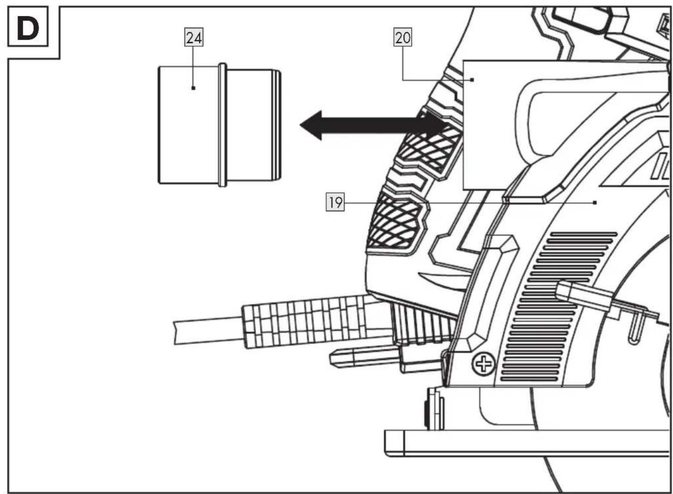
Connecting to dust ktraction
(Fig. D)
NOTE
The adap24 can be fitted to most of the commonly available dust extraction systems or devices (e.g. vacuum cleaner hose).
Installing the adaptor
- Unscrew the adaptor 24 from the dust port 20 with a rotary motion.
- Connect the adaptor 24 to the dust extraction system.
Removing the adaptor
- Turn the adaptor 24 in clockwise and anti-clockwise directions repeatedly.
- Pull the adaptor 24 away from the dust port 20.
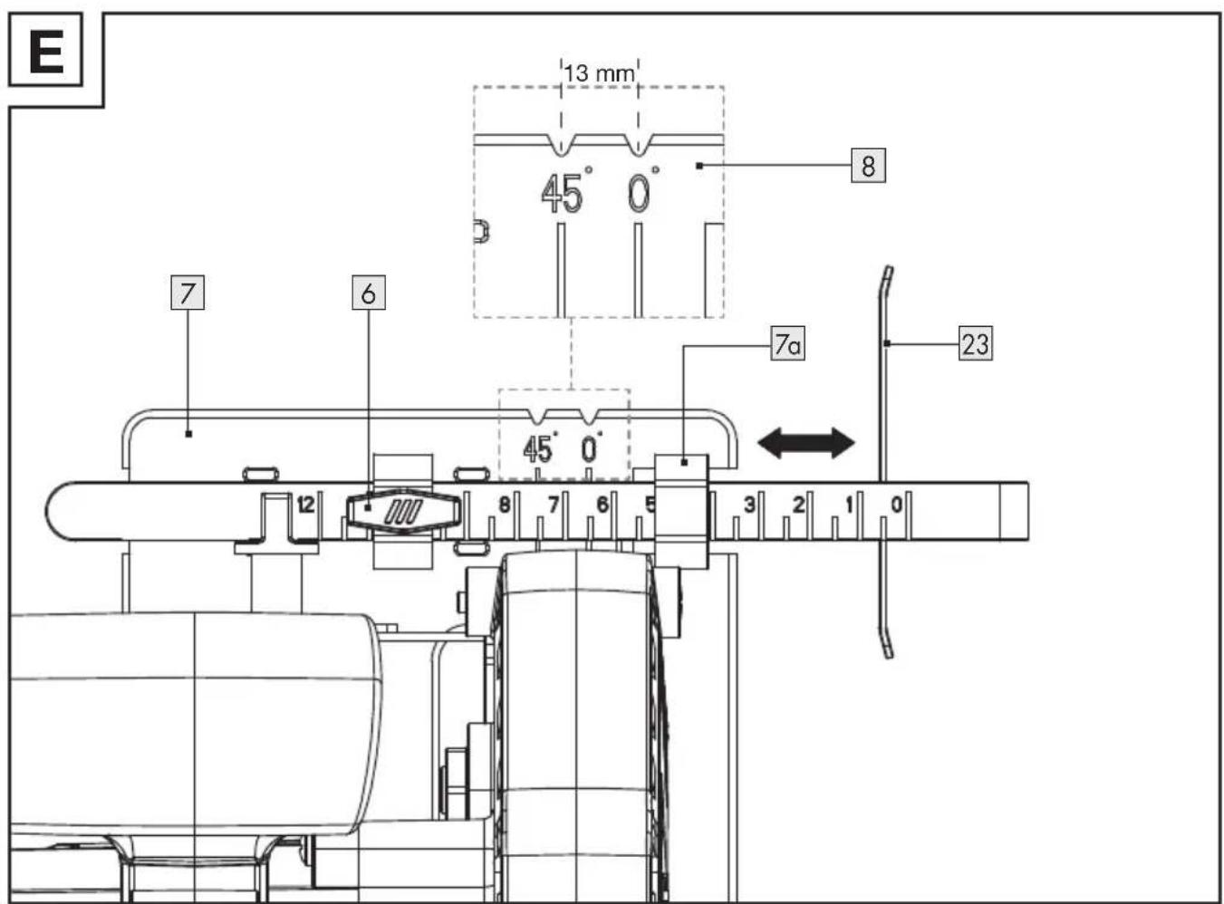
- Mounting the parallel fence
- Adjusting the cutting depth
(Fig. E)
NOTE
The cutting width is showing on the scale of the parallel fence 23.
Measuring the cutting width when the product is set to a cutting angle of 0^ or 45^ : The cutting guide 8 indicates the reference point.
The distance scale shown on the parallel fence 23 is an appropriate value.
- Set the cutting angle to 0^ (see “Adjusting the cutting angle”).
- Loosen the wing screw 6.
- Insert the parallel fence 23 to the holder on the base plate 7.
- Adjust the distance of the parallel fence 23 to the desired cutting width.
- Fixing the parallel fence 23 in place: Tighten the wing screw 6.
- When you set the cutting angle to 45^ , the actual cutting width obtained is equal to the distance scale reading on the parallel fence 23 plus 13 mm (distance between the markings for 45^ and 0^ on the cutting guide 8).
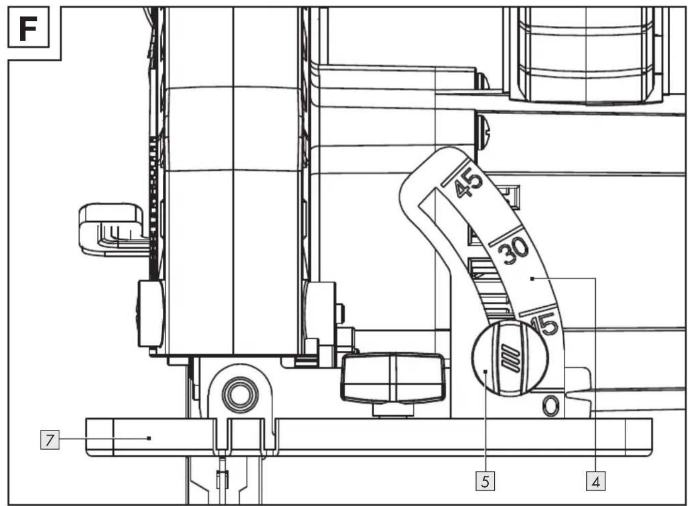
- Adjusting the cutting angle
(Fig. F)
- Loosen the wing screw for cutting angle preselection 5 of the cutting angle scale 4.
- Hold the base plate 7 with one hand.
- Setting the desired cutting angle: Move the main handle 21 with the other hand. Check the angle on the cutting angle scale 4.
- Tighten the wing screw for cutting angle preselection 5.
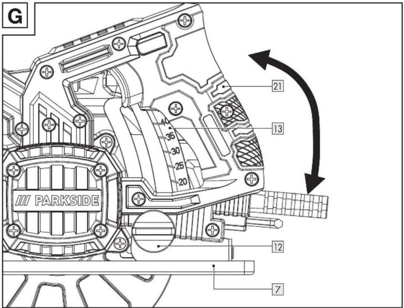
(Fig. G)
- Unlocking the cutting depth scale 13 : Turn the wing screw 12 in anti-clockwise direction.
- Hold the base plate 7 with one hand.
- Setting the desired cutting depth: Move the main handle 21 with the other hand. Check the cutting depth on the cutting depth scale 13.
- Locking the cutting depth scale 13 : Turn the wing screw 12 in clockwise direction.
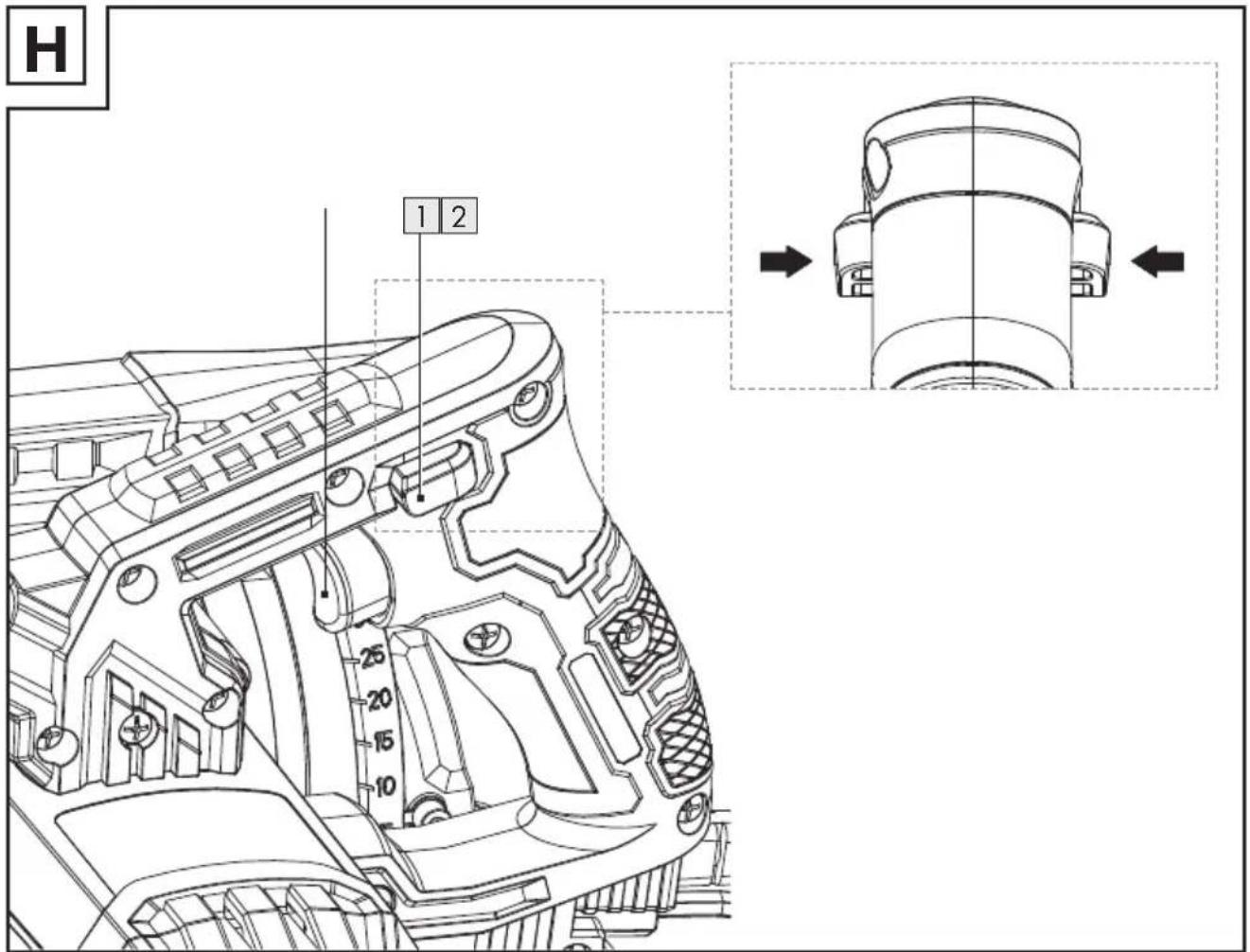
- Switching on/off
(Fig. H)
Switching on
- Connect the mains plug 9 to a suitable mains outlet.
- Press and hold the switch lock 1 from either side.
- Press down the on/off switch 2. The product starts to operate.
- Release the switch lock 1.
Switching off
- Release the on/off switch 2.
- Remove the mains plug 9 from the mains outlet.
Work instructions
NOTE
Always hold the product firmly with both hands: Hold the main handle 21 with one hand and the auxiliary handle 3 with the other hand.
Allowing the saw blade ^15 to spin up to full speed: Allow the product to start up before processing the workpiece.
NOTE
Saw forward with a suitable and moderate pressure applied to the product.
▶ Moving the product sideways during cutting works cause jamming of the saw blade 15 and burning of the cutting teeth and the blade body. This could result in kickback.
● Cleaning and care

WARNING!

Always switch the product off, remove the mains plug 9 from the mains outlet and let the product cool before performing inspection, maintenance and cleaning work!

Cleaning
NOTE
Do not use chemical, alkaline, abrasive or other aggressive detergents or disinfectants to clean this product as they might be harmful to its surfaces.
▶ Never allow fluids to get into the product.
■ Regular and proper cleaning will help ensure safe use and prolong the life of the product.
☐ The product must always be kept clean, dry and free from oil or grease. Remove debris from it after each use and before storage.
□ Clean the product with a dry cloth. Use a soft brush for areas that are hard to reach.
Maintenance
■ The product is maintenance-free.
Before and after each use, check the product and accessories (e.g. saw blades) for wear and damage. If required, exchange them for new ones as described in this instruction manual.
Observe the technical requirements (see "Technical data").
☐ Check covers and safety devices for damages and correct installation. Replace as necessary.
☐ Replace a blunt or bent saw blade or one which has been damaged in some other way.
Replacement parts/Accessories
- Customers can obtain compatible replacement parts and accessories via www.optimex-shop.com.
- Orders can only be placed and processed online.
□ Have the order number ready for your order.
□ Contact the Lidl service hotline (see „Service“) for further information.
| Part Order number | ||
| 10 | Hex key 9994579 | 0103 |
| 15 | Saw blade 99945 | 790101 |
| 23 | Parallel fence 999 | 45790102 |
| 24 | Adaptor 9994579 | 0104 |
Repair
If the mains cord 9 is damaged, it must be replaced by the manufacturer, its service agent or similarly qualified persons in order to avoid a hazard.
☐ This product does not contain any parts that can be repaired by the user. Contact an authorised service centre or a similarly qualified person to have it checked and repaired.
Storage
Before storage: Clean the product (see "Cleaning").
□ Store the product and its accessories in a dark, dry, frost-free, well-ventilated place.
□ Always store the product in a place that is inaccessible to children.
□ Store the product in its original package.
- Transportation
□ Transport the product in its original package.
□ Protect the product from any heavy impact or strong vibrations which may occur during transportation in vehicles.
☐ Secure the product to prevent it from slipping or falling over.
● Disposal
The packaging is made entirely of recyclable materials, which you may dispose of at local recycling facilities.
Observe the marking of the packaging materials for waste separation, which are marked with abbreviations (a) and numbers (b) with following meaning: 1–7: plastics/20–22: paper and fibreboard/80–98: composite materials.
Product:

The product and packaging materials are recyclable and are subject to extended producer responsibility. Dispose them separately, following the illustrated Info-tri (sorting information), for better waste treatment.
The Triman logo is valid in France only.

Contact your local refuse disposal authority for more details of how to dispose of your worn-out product.
To help protect the environment, please dispose of the product properly when it has reached the end of its useful life and not in the household waste. Information on collection points and their opening hours can be obtained from your local authority.
Warranty
The product has been manufactured to strict quality guidelines and meticulously examined before delivery. In the event of material or manufacturing defects you have legal rights against the retailer of this product. Your legal rights are not limited in any way by our warranty detailed below.
The warranty for this product is 3 years from the date of purchase. The warranty period begins on the date of purchase. Keep the original sales receipt in a safe location as this document is required as proof of purchase.
Any damage or defects already present at the time of purchase must be reported without delay after unpacking the product.
Should the product show any fault in materials or manufacture within 3 years from the date of purchase, we will repair or replace it – at our choice – free of charge to you. The warranty period is not extended as a result of a claim being granted. This also applies to replaced and repaired parts.
This warranty becomes void if the product has been damaged, or used or maintained improperly.
The warranty covers material or manufacturing defects. This warranty does not cover product parts subject to normal wear and tear, thus considered consumables (e.g. batteries, tubes, cartridges), nor damage to fragile parts, e.g. switches or glass parts.
● Warranty claim procedure
So that your request can be processed quickly, please observe the following instructions:
For all inquiries, please have the receipt and item number (IAN 487372_2501) ready as proof of purchase.
The article number can be taken from the identification label on the product, engraving on the product, the front cover of your manual (at the bottom left), or the sticker on the back or bottom of the product.
If malfunctions or other defects arise, first contact the service department indicated below by phone or email. You can then send a product recorded as defective to the communicated service address postage-free, making sure to enclose proof of purchase (receipt) and information on the details of the defect and when it occurred.

You can download and view this and numerous other manuals at parkside-diy.com. This QR code takes you directly to parkside-diy.com. Choose your country and use the search screen to search for the operating instructions. Entering the item number (IAN) 487372_2501 takes you to the operating instructions for your item.
Service
GB Service Great Britain
Tel.:08000569216
E-Mail:owim@lidl.co.uk
IE Service Ireland
Tel.:1800200736
E-Mail:owim@lidl.ie
EU Declaration of conformity
EU DECLARATION OF CONFORMITY (No. 487372\_2501)
IAN:
487372_2501
Product identification:
"PARKSIDE" Circular saw
Model Number:
HG11714
The object of the declaration described above is in conformity with the relevant Union harmonisation legislation:
| Directive 2006/42/EC |
| Directive 2014/30/EU |
| Directive 2011/65/EU and all related amendments |
References to the relevant harmonised standards used or references to the other technical specifications in relation to which conformity is declared:
| N° / Parts |
| Directive 2006/42/EC |
| EN 62841-1:2015/A11:2022 |
| EN 62841-2-5:2014 |
| Directive 2014/30/EU |
| EN IEC 55014-1:2021 |
| EN IEC 55014-2:2021 |
| EN IEC 61000-3-2:2019/A1:2021 |
| EN 61000-3-3:2013/A2:2021 |
The object of the declaration described above is in conformity with Directive 2011/65/EU of the European Parliament and of the Council of 8 June 2011 on the restriction of the use of certain hazardous substances in electrical and electronic equipment:
| N° / Parts |
| Directive 2011/65/EU |
| EN IEC 63000:2018 |
Keeper of the technical documentation: OWIM GmbH & Co.KG
Signed for and on behalf of:
This declaration of conformity is issued under the sole responsibility of the manufacturer.
Translation of the original declaration of conformity
Neckarsulm
Place
21.02.2025
Date

Authorised Signatory

Authorised Signatory
EN
CE


- HANDKREISSÄGE/CIRCULAR SAW/SCIE CIRCULAIRE PHKS 750 A1
- HANDKREISSÄGE
- SCIE CIRCULAIRE
- List of pictograms used ...... Page 27
- Introduction ...... Page 28
- Safety instructions ...... Page 30
- Before first use.... Page 36
- Preparation...... Page 36
- Cleaning and care Page 39
- Disposal Page 40
- Warranty.... Page 40
- Service Page 41
- EU Declaration of conformity.... Page 42
- CIRCULAR SAW
- - Introduction
- Intended use
- - Scope of delivery
- WARNING!
- Circular Saw
- Parts description
- Noise emission value
- Vibration emission value
- NOTE
- Safety instructions
- Save all warnings and instructions for future reference.
- Work area safety
- Electrical safety
- Personal safety
- Power tool use and care
- Service
- ● Vibration and noise reduction
- ● Behaviour in emergency situations
- - Residual risks
- ● Safety instructions for circular saws
- Sawing method
- ● Further safety instructions for all saws
- Kickback – causes and related warnings
- ● Lower guard function
- Additional safety warnings
- ● Safety information for the saw blade
- Before first use
- Unpacking the product
- Accessories
- Preparation
- WARNING! Risk of injury!
- CAUTION! Risk of injury!
- (Fig. C)
- Removing the saw blade
- Installing the saw blade
- Connecting to dust ktraction
- (Fig. D)
- Installing the adaptor
- Removing the adaptor
- - Mounting the parallel fence
- - Adjusting the cutting depth
- (Fig. E)
- - Adjusting the cutting angle
- (Fig. F)
- (Fig. G)
- - Switching on/off
- (Fig. H)
- Switching on
- Switching off
- Work instructions
- ● Cleaning and care
- Cleaning
- Maintenance
- Replacement parts/Accessories
- Repair
- Storage
- - Transportation
- ● Disposal
- Product:
- Warranty
- ● Warranty claim procedure
- EU Declaration of conformity
- EU DECLARATION OF CONFORMITY (No. 487372\_2501)
Brand : PARKSIDE
Model : PHKS 750 A1
Category : Electric saw