VXL7 - TV wall mount SANUS - Free user manual and instructions
Find the device manual for free VXL7 SANUS in PDF.

| Product Type | TV wall mount |
| Brand | SANUS |
| Model | VXL7 |
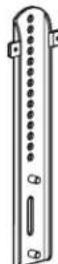
| Wall plate dimensions | 700 x 407 mm (approx) |
| Bracket weight | 5 kg (approx) |
| Maximum load | 40 kg (88 lbs) |
| VESA compatibility | Up to 700 x 400 mm |
| Material | Steel |
| Color | Black |
| Main features | Tilt, level adjustment, cable release |
| Installation type | On wood studs, solid concrete or concrete blocks |
| Included accessories | Hardware, drilling template |
| Warranty | 5 years |
| Care and cleaning | Clean with a soft dry cloth |
| Safety | Safety lock, release cables |
| Spare parts and repairability | Available upon request from customer service |
| General information | Assisted installation with HeightFinder™, online video available |
Frequently Asked Questions - VXL7 SANUS
User questions about VXL7 SANUS
0 question about this device. Answer the ones you know or ask your own.
Ask a new question about this device
Download the instructions for your TV wall mount in PDF format for free! Find your manual VXL7 - SANUS and take your electronic device back in hand. On this page are published all the documents necessary for the use of your device. VXL7 by SANUS.
USER MANUAL VXL7 SANUS
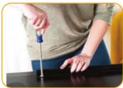
Follow this step-by-step instruction manual to speed up your installation.
WE'RE HERE TO HELP
Want to watch a video that shows how easy this DIY project will be?
Watch it now at:
SANUS.com/3283

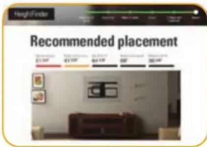
Get it right the first time. HeightFinderTM shows you where to drill.

Check it out at:
SANUS.com/2567


Our install experts are standing by to help.

Call us at:
US: +1 (800) 359-5520
EMEA: +31 (0) 495 580 852
UK: +44 (0) 800 056 2853
Before you begin
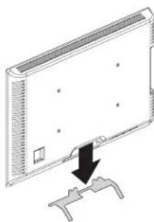
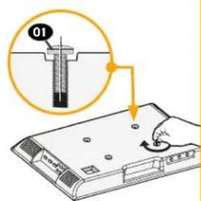
Remove the stand
from your TV - if attached.
Your TV product sticker may be inaccessible after mounting
BEFORE MOUNTING YOUR TV:

Record your TV information and save for future reference.

Or, take a photo of your TV product sticker and save for future reference.
Brand:
Model No.:
Serial No. (S / N) ..
Version/SCC/Other:
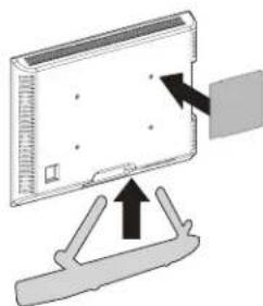
Install any accessories
you may have purchased if they require the TV to be removed from the wall for assembly. The TV is removable for future accessory purchases.
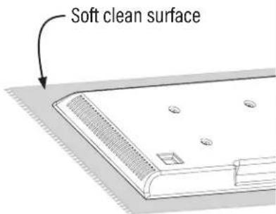
Protect the face
of your TV when laying it down for installation.
IMPORTANT SAFETY INSTRUCTIONS - PLEASE READ MANUAL PRIOR TO USE - SAVE THESE INSTRUCTIONS
Please read through these instructions completely to be sure you're comfortable with this easy install process.
Check your TV owner's manual to see if there are any special requirements for mounting your TV.
If you do not understand these instructions or have doubts about the safety of the installation, assembly or use of this product,
contact Customer Service: +1 (800) 359-5520 (EMEA: +31 (0) 495 580 852; UK: +44 (0) 800 056 2853)
SAUTION: Avoid potential personal injuries and property damage!
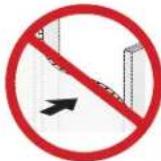
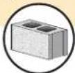
- This product is designed ONLY to be installed into wood studs, solid concrete or concrete block.
- DO NOT INSTALL INTO DRYWALL ALONE - DRYWALL ALONE WILL NOT HOLD THE WEIGHT OF YOUR TV.
This product is designed for INDOOR USE ONLY. - The wall must be capable of supporting five times the weight of the TV and mount combined.
- Do not use this product for any purpose not explicitly specified by manufacturer.
Manufacturer is not responsible for damage or injury caused by incorrect assembly or use.
TV Weight Limit
(including accessories)
DO NOT EXCEED
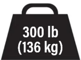
If your TV (including accessories) exceeds this weight, this mount is NOT compatible.
Visit SANUS.com or call customer service to find a compatible mount.
Wall Construction
ONLY install on these acceptable wall types.

Unsure
Call
Customer
Service

CAUTION:
DO NOT install
in drywall alone
Drywall
alone will
NOT hold
the weight
of your TV.
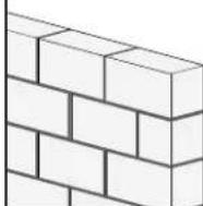
wood studs Solid concrete
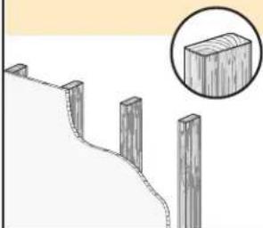
ACCEPTABLE ACCEP
or concrete block
.E
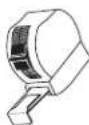
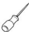
Tools Needed
Measure
Pencil Level Tape

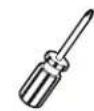
ScrewdriverTape
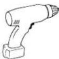
Electric Drill
Socket Wrench
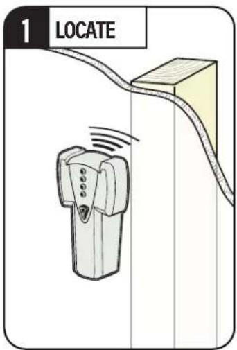
Wood Stud Install
Stud Finder
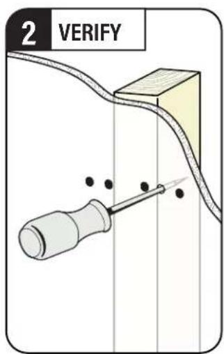
Awl

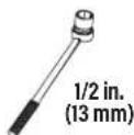
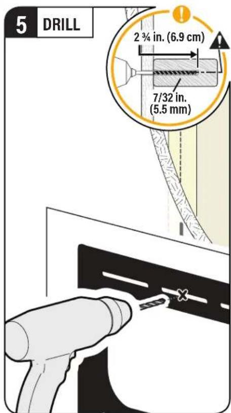
7/32 in. (5.5 mm) Wood
Woo
Drill Bit
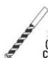
Concrete Install
Drill Bit
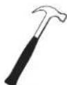
Hammer
Attach TV Bracket to TVSTEP1

WARNING: This product contains small items that could be a choking hazard if swallowed. Before starting assembly, verify all parts are included and undamaged. If any parts are ing or damaged, do not return the damaged item to your dealer; contact Customer Service. Never use damaged parts!

NOTE: Not all hardware included will be used.
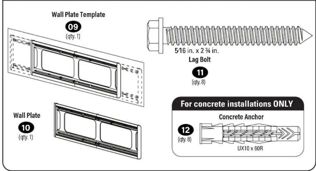
STEP1 Parts and Hardware

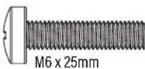
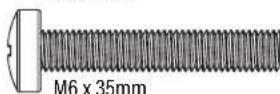
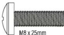
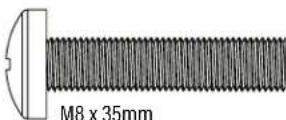
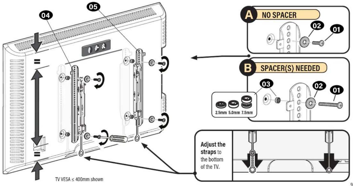
TV Screws
[Only one size fits your TV] (qty. 4 each)
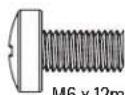
M6
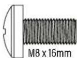
M8
Washer
ty.4 each)

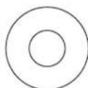
M6/M8
Spacers
[If necessary] (qty. 4 each)

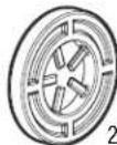
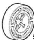
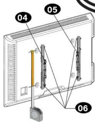
TV Brackets
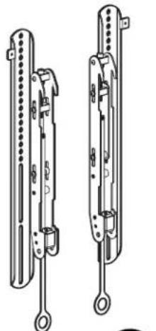
04
(qty.1)

(qty.1)
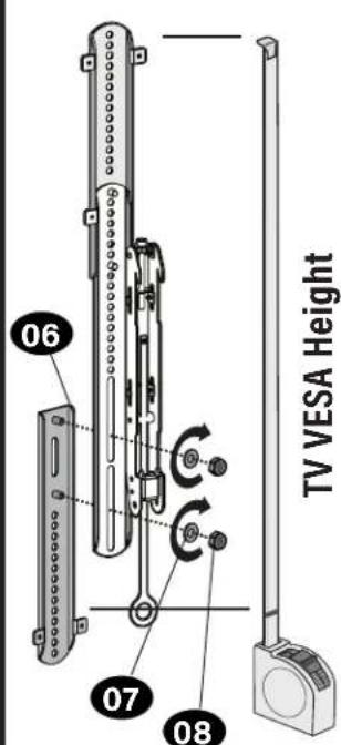
TV Bracket Extension


Washer

(qty.8)

Nut

(qty.8)
Only one screw size fits your TV.
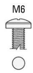
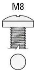
1.2 Determine TV Screw Length and Spacers1.1 TV Screw Diameter
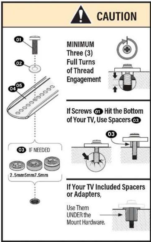
1.3 Determine Your TV Bracket Configuration
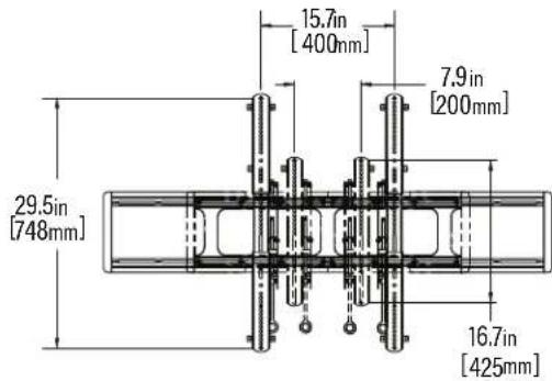
Measure the HEIGHT of your TV mounting hole pattern.
For Height 400mm or less
Skip to STEP 1.4 on PAGE 9
≤ 400mm (15%) in.)
For height greater than 400mm
Assemble TV bracket extensions 06 to fit over your TV VESA height.
400mm (15 3/4 in.)
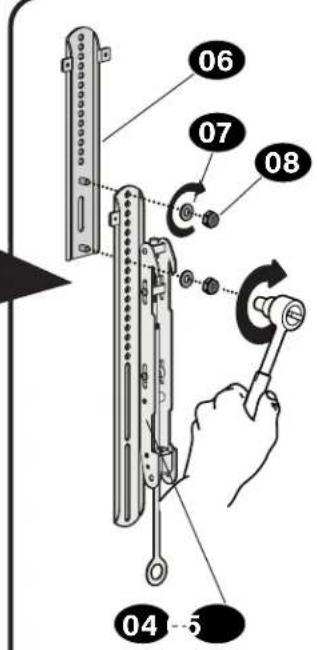
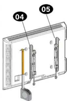
1.4 Attach TV Brackets to Your TV
Center the TV brackets 04 and 05 on your TV hole pattern, and install using your screw/washer/spacer.
STEP2
Attach Wall Plate to Wall
WARNING: This product contains small items that could be a choking hazard if swallowed. Before starting assembly, verify all parts are included and undamaged. If any parts are missing or damaged, do not return the damaged item to your dealer; contact Customer Service. Never use damaged parts!

Not all hardware included will be used.
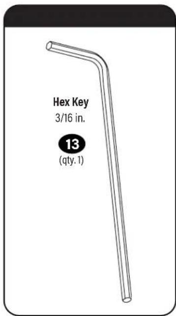
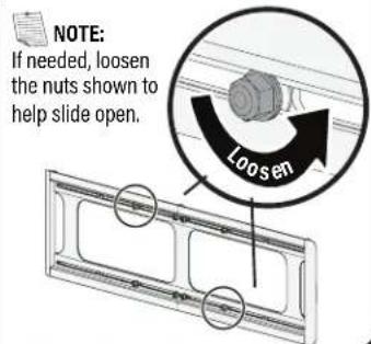
Parts and Hardware for STEP 2 Tool for Adjustments
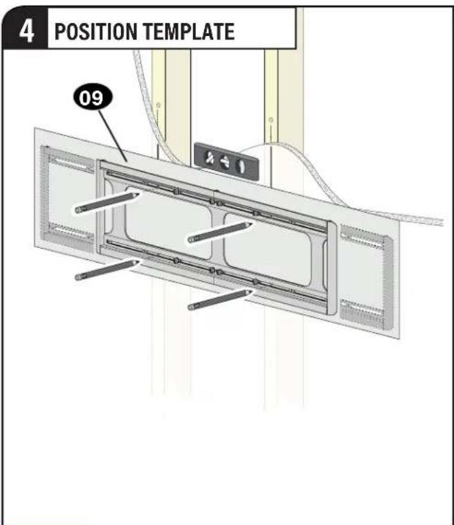
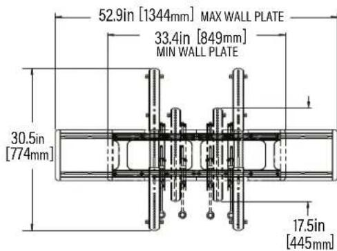
Determine Your Wall Plate Configuration
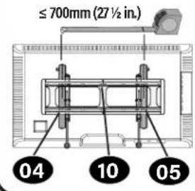
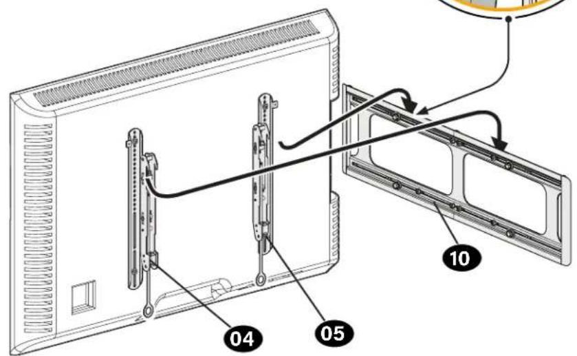
Measure the distance between your TV brackets 04/05
For TV brackets 700mm or less *
Skip to STEP: 2A (wood Stud) on PAGE 12 or 2B (concrete) on PAGE 15
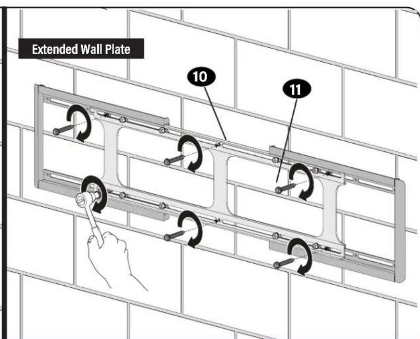
For TV brackets greater than 700mm
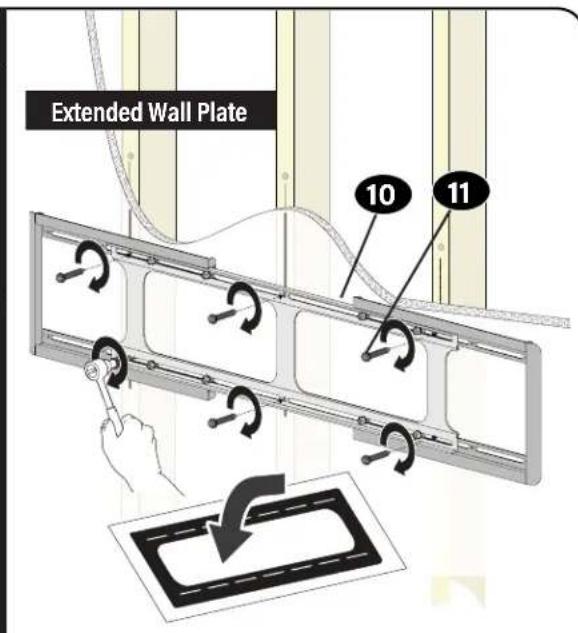
Extend the wall plate to fit the TV brackets.
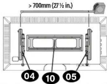
Extend your wall plate 10 beyond your TV brackets 04/05, but not past your TV edges.
WARNING: Avoid potential personal injuries! These areas could be pinch points when sliding back together.
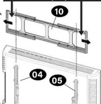
* NOTE: For Wood Stud Installations ONLY: You can extend the wall plate to allow your TV to shift side-to-side. Be sure to not extend the wall plate past your TV edge.
STEP2A
Wood Stud Installation
CAUTION: Avoid potential personal injury or property damage!
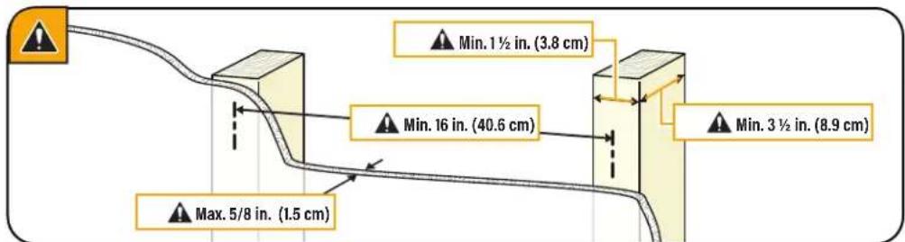
- Drywall covering the wall must not exceed 5/8 in. (1.5 cm)
Minimum wood stud size: common 2 × 4 in. (5.1 x 10.2 cm) nominal 112 × 312 in. (3.8 x 8.9 cm)
Minimum horizontal space between fasteners:16 in. (40.6 cm)
Stud centers must be verified
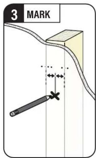

TIP:
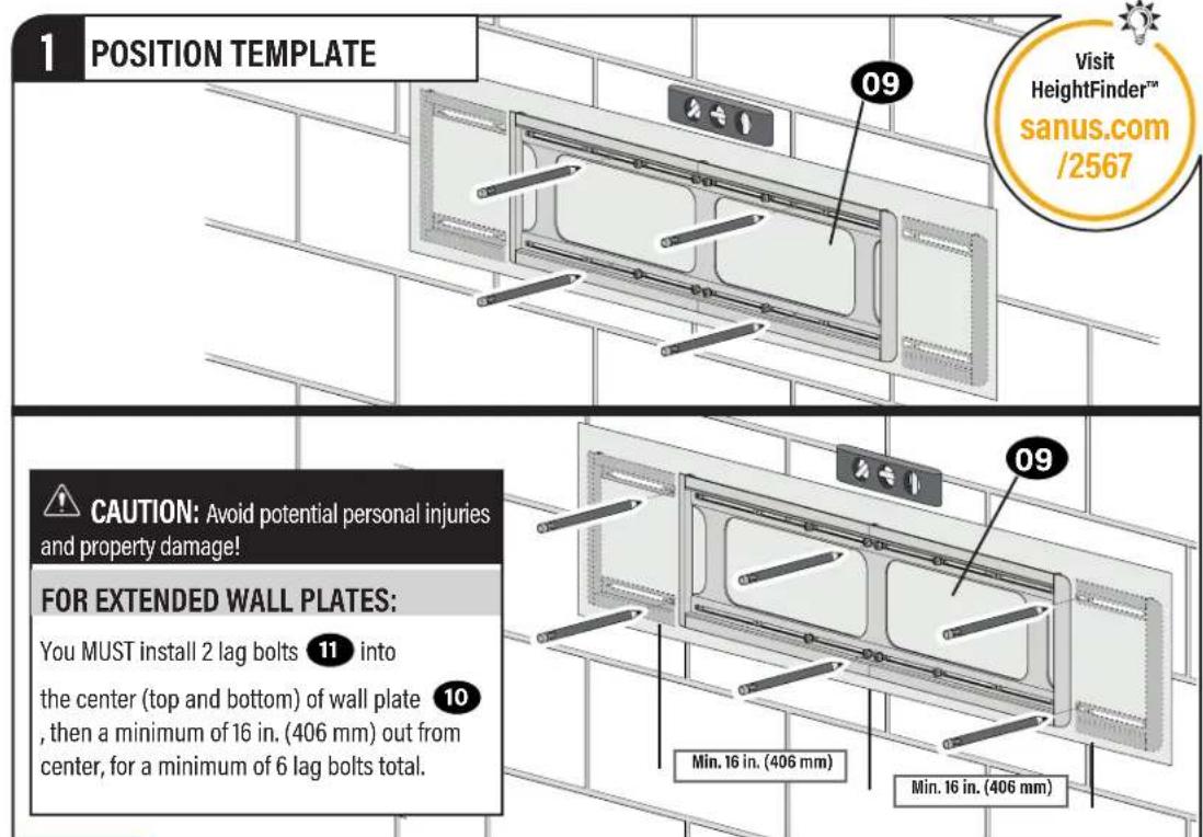
To calculate your precise wall plate location, check out our HeightFinder at sanus.com [www.sanus.com/2567].
STEP2A
(continued)
CAUTION: Avoid potential personal injury or property damage!
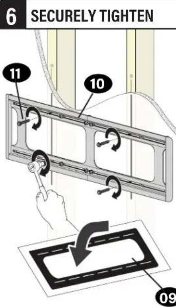
All lag bolts 11 MUST BE firmly tightened to prevent unwanted movement of the wall plate 10. Ensure the wall plate is securely fastened to the wall before continuing on to the next step.
Go to STEP 3 on PAGE 18.
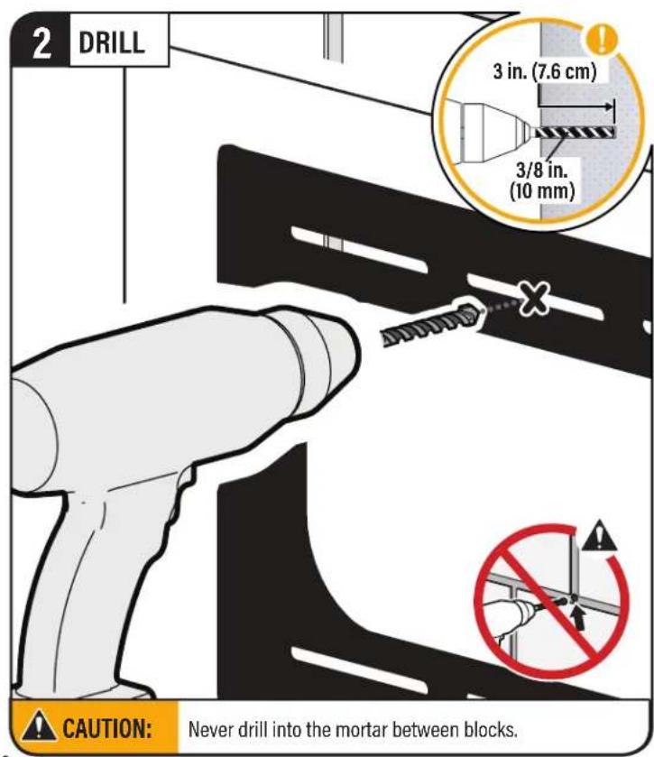
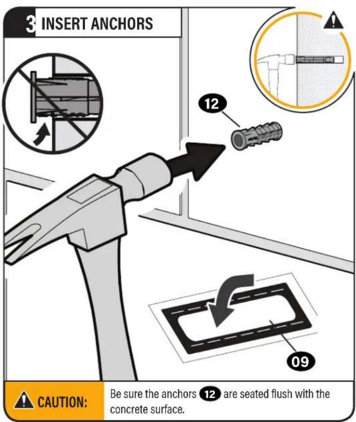
STEP 2B
Solid Concrete or Concrete Block Installation
CAUTION:
Avoid potential personal injury or property damage!
Mount the wall pla directly onto the concrete surface (no surface covering)
Minimum solid concrete thickness: 8 in. (20.3 cm)
Minimum concrete block size: 8 x 8 x 16 in. (20.3 x 20.3 x 40.6 cm)
Minimum horizontal space between fasteners: 16 in. (40.6cm)
For concrete applications, TV brackets 04 and 05 must remain centered in wall plate 10. Keep this in mind when selecting the wall plate location

TIP:
To calculate your precise wall plate 10 location, check out our HeightFinder at sanus.com [www.sanus. com/2567].
STEP2B
(continued)


CAUTION: Avoid potential personal injury or property damage!
All lag bolts 11 MUST BE firmly tightened to prevent unwanted movement of the wall plate 10. Ensure the wall plate is securely fastened to the wall before continuing on to the next step.
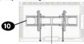
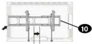
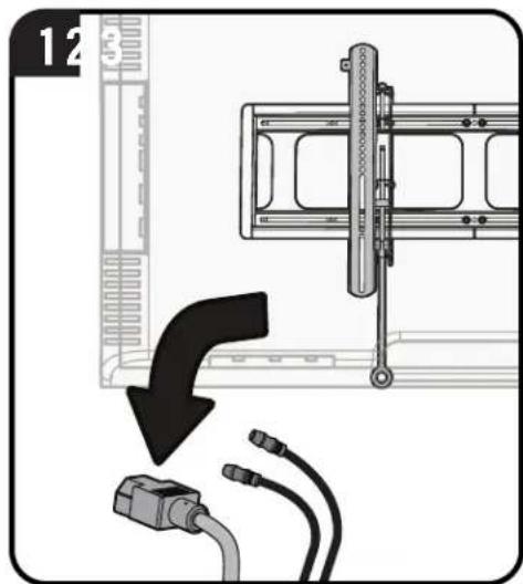
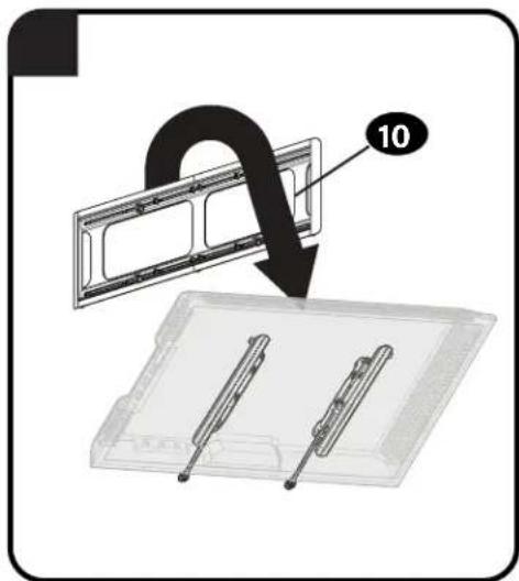
STEP3
Attach TV to Wall Plate

CAUTION:
Avoid potential personal injury or property damage!
For CONCRETE APPLICATIONS:
TV brackets 04 and 05 MUST remain
centered in wall plate 10
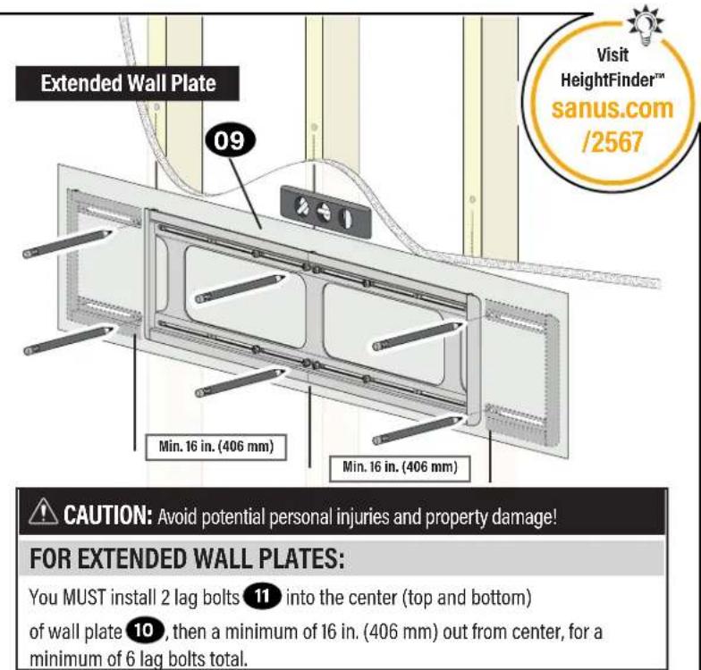
For extended wall plates:
TV brackets 04 and 05 must only hang on the OUTER sections of wall plate 10.
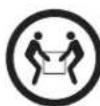
1 HANG

HEAVY! You may need assistance with this step.
2 ATTACH
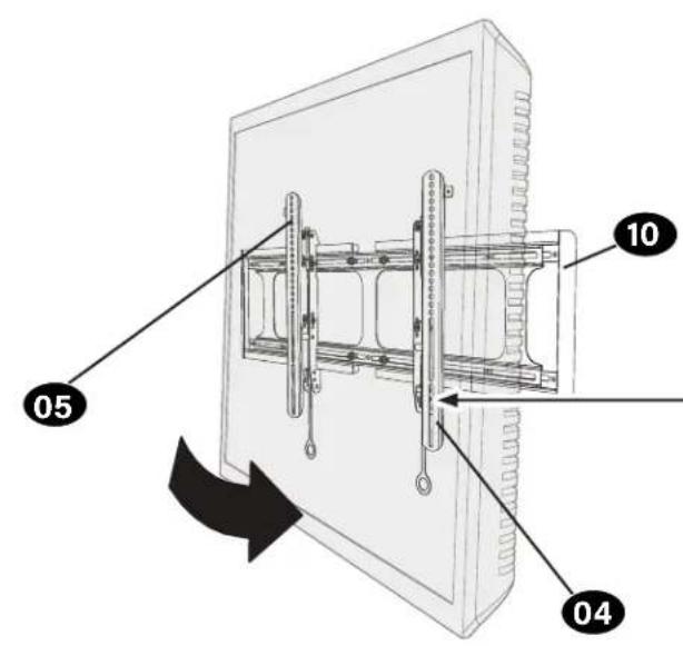
CAUTION: Avoid potential personal injury or property damage!
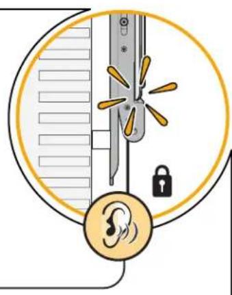
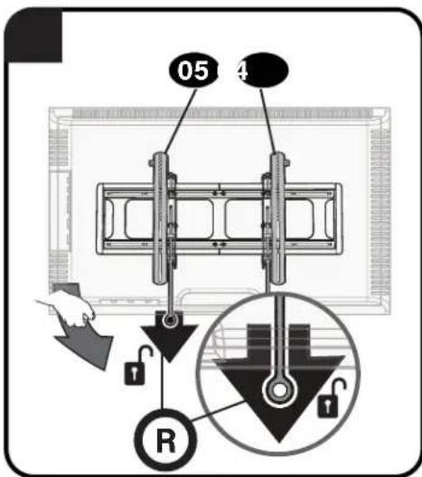
Always make sure TV brackets 04 and 05 are in the locked position so the TV is securely fastened to the wall plate 10
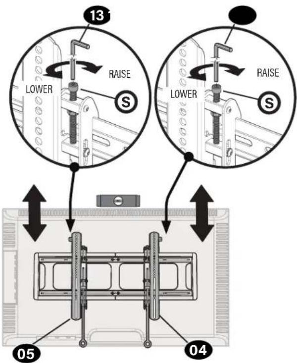
Adjustments
LEVELHEIGHT
To level your TV, turn the level adjustment screw
on the top of either TV bracket 04 and 05 to raise or lower that respective side of the TV.
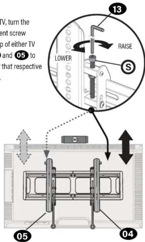
Adjust the height by turning the level adjustment screw on the top of both TV brackets 04 and 05
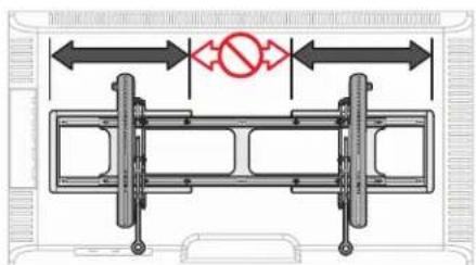
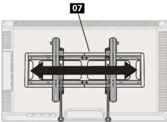
TV LATERAL SHIFT

CAUTION: Avoid potential personal injury or property damage!
For CONCRETE APPLICATIONS: TV brackets 04 and 05 MUST remain centered in wall plate 10

CAUTION: Avoid
potential personal injury or property damage!
Slowly slide the TV along the
wall plate to reposition. The wall plate has built-in stops to limit lateral movement.
REMOVING THE TV
CAUTION: Avoid potential personal injury or property damage!
To prevent breaking the locking latch: always pull and hold release tabs R down while pulling the TV away from the wall.

NOTE: To rehang the TV, follow the procedures in STEP 3 on PAGE 18.
Dimensions
TV INTERFACE
TOP VIEW-TV MOUNTED
TOP VIEW
WALL IS ON TOP

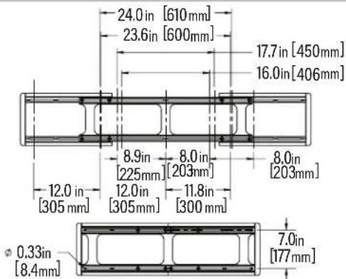
WALLPLATE
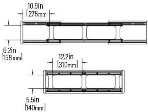
FULLY ASSEMBLED MOUNT
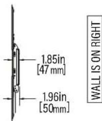
SIDE VIEW
ESPANOL
Thank you for choosing SANUS! Please take a moment to let us know how we did:
Legrand AV Inc.
6436 City West Parkway
Eden Prairie, MN 55344 USA
US: +1 (800) 359-5520
Legrand AV Netherlands B.V.
Franklinstraße 14
6003 DK Weert Netherlands
UK: +44 (0) 800 056 2853
EMEA: +31 (0) 495 580 852
Authorized Representative for the UK
Starline Holding Technology Ltd.
Unit C Island Road
Reading RG2 ORP UK
Legrand AV Inc. and its affiliated corporations and subsidiaries (collectively, "Legrand"), intend to make this manual accurate and complete. However, Legrand AV makes no claim that the information contained herein covers all details, conditions, or variations. Nor does it provide for every possible contingency in connection with the installation or use of this product. The information contained in this document is subject to change without notice or obligation of any kind. Legrand AV makes no representation of warranty, expressed or implied, regarding the information contained herein. Legrand AV assumes no responsibility for accuracy, completeness or sufficiency of the information contained in this document.
©2025 Legrand AV Inc. All rights reserved. SANUS is a brand of Legrand. SANUS and the SANUS logo are registered trademarks of Legrand. All other brand names or marks are used for identification purposes and are trademarks of their respective owners.
Legrand AV Inc. - 6436 City West Parkway - Eden Prairie, MN 55344 USA


图1
ELEMENTS DEMPBALLAGE
ELEMENTI DI MBALLAGIO

6901-603471 00