VTM6 - TV wall mount SANUS - Free user manual and instructions
Find the device manual for free VTM6 SANUS in PDF.

User questions about VTM6 SANUS
0 question about this device. Answer the ones you know or ask your own.
Ask a new question about this device
Download the instructions for your TV wall mount in PDF format for free! Find your manual VTM6 - SANUS and take your electronic device back in hand. On this page are published all the documents necessary for the use of your device. VTM6 by SANUS.
USER MANUAL VTM6 SANUS
IMPORTANT SAFETY INSTRUCTIONS – SAVE THESE INSTRUCTIONS – PLEASE READ ENTIRE MANUAL PRIOR TO USE
We are here to help!
Please contact Customer Service with any questions.
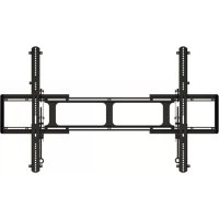
natural_image
Technical line drawing of a square electronic device with circular patterns and mounting brackets (no text or symbols)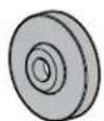

-sanus.com
Customer Service
Americas: 800-359-5520 · 952-225-6013 · info@sanus.com
Europe, Middle East, and Africa: +31 (0) 495 580 852 • europe.sanus@milestone.com
Asia Pacifi c: 86 755 8996 9226 • sanus.ap@milestone.com
SANUS • 6436 City West Parkway • Eden Prairie, MN 55344 USA
©2012 Milestone AV Technologies, a Duchossois Group Company. All rights reserved. Sanus is a division of Milestone.
All other brand names or marks are used for identification purposes and are trademarks of their respective owners.
English - How to use this manual
For best results, reference both the text and illustrations.
English Text Pages 3-13
This product is only compatible with the 2nd and 3rd generation iPad® tablets - including iPad® tablets in a smart cover.
▲ CAUTION: Avoid potential personal injuries and property damage!
Do not use this product for any purpose not explicitly specified by manufacturer.
If you do not understand these instructions, or have doubts about the safety of the installation, assembly or use of this product, contact Customer Service or call a qualified contractor.
Manufacturer is not responsible for damage or injury caused by incorrect assembly or use.

WARNING: This product contains a magnet. If an implanted medical device such as a pacemaker or implantable cardioverter Iator (ICD) is in use, magnetic fields may affect the operation of those devices, resulting in serious injury or death. If you have planted medical device, keep at least 13 cm (5 in.) between your device and the magnet. Please consult with your physician or all professional prior to using this product.
⚠ WARNING: Do not attach the holder [01] to the wall plate [02] unless the wall plate is mounted to a wall. Separation would be difficult and could damage the holder.
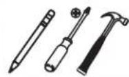
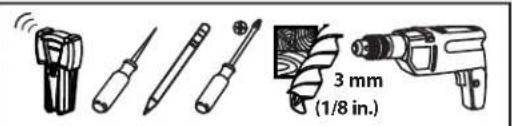
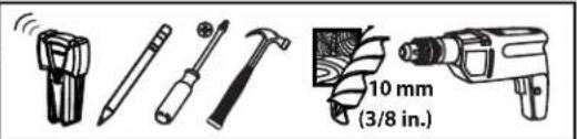
Required Tools
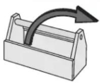
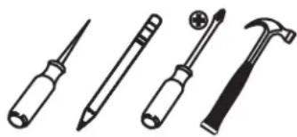
natural_image
Illustration of four different types of screwdrivers and tools: a screwdriver, a screwdriver with a hammer, a hammerhead, and a flat screwdriver (no text or symbols present)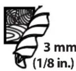
Supplied Parts and Hardware
WARNING: This product contains small items that could be a choking hazard if swallowed.
Before starting assembly, verify all parts are included and undamaged. If any parts are missing or damaged, do not return the damaged item to your dealer; contact Customer Service. Never use damaged parts!
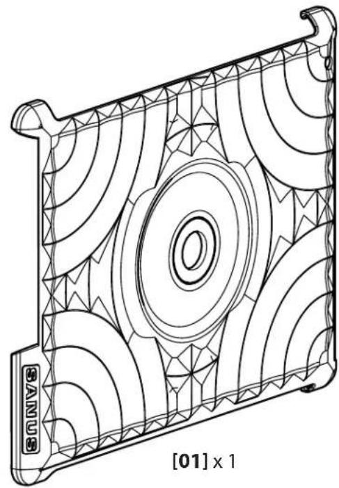
natural_image
Technical line drawing of a mechanical component with concentric circular patterns and a central circular hole (no text or symbols)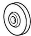
[02] × 2
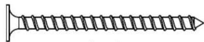
8 x 2 in.
[03] × 2
![[03] [04] x 2](/content/2026/04/673686/images/3073119dcfa314e16df7e736b2dac5d8698c3b300c84c1e03638f5b1acb8153e.jpg)
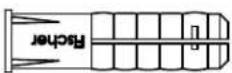
[05] × 2
Wall Mount
Solid Concrete or Concrete Block
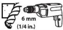
![Place the wall plate [02] on the wall and mark the hole location. ⚠️ CAUTION: Avoid potential injuries or property damage! ■ Mount the wall plate [02] directly onto the concrete surface. ■ Minimum solid concrete thickness: 203mm (8 in.). ■ Minimum concrete block size: 203 x 203 x 406 mm (8 x 8 x 16 in.).](/content/2026/04/673686/images/56c0f54cc0a471d4bf618eec7ed0ac952aab501f5db86fb4fa7b763973b4f04b.jpg)
![Insert anchors [05] into drilled holes. [05]](/content/2026/04/673686/images/00f25e1de08abf6061d82b0a70e75a71b3563ec5a46b6b3c3f0332e939200234.jpg)
![4 ▲ CAUTION:Improper use could reduce the holding power of the mounting screw [03]. To avoid potential injuries or property damage: DO NOT over-tighten the mounting screw [03]. [02] [03]](/content/2026/04/673686/images/69e18bfaa4271e02dbfdbfd85151423f34de5a70b5d9968b891df4af7797d748.jpg)
Wall Mount
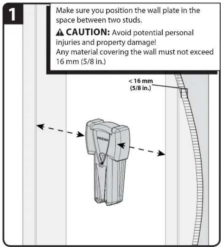
Wood Stud
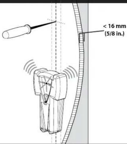
1
Verify the center of the stud using an awl, a thin nail, or an edge to edge stud finder.
⚠️ CAUTION: Avoid potential personal injuries and property damage!
Any material covering the wall must not exceed 16 mm (5/8 in.)
Minimum wood stud size: common 51 x 102 mm (2 x 4 in.) nominal 38 x 89 mm (1½ x 3½ in.)
2
Place the wall plate [02] on the wall and mark the hole location.
![[02]](/content/2026/04/673686/images/8906e7759f8464770188ef284e61985e4fc32c6188e65807827b0378c806d61a.jpg)
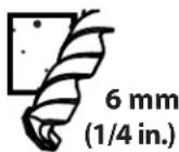
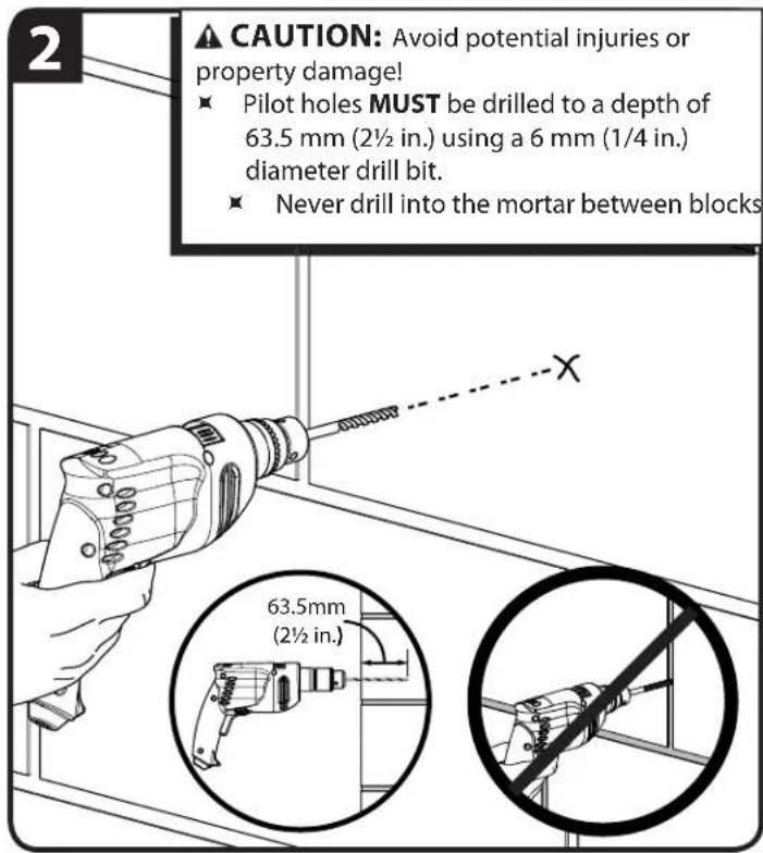
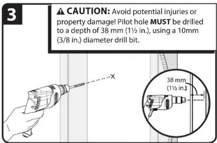
3
CAUTION: Avoid potential injuries or property damage! Pilot holes MUST be drilled to a depth of 63.5 mm (2½ in.) using a 3 mm (1/8 in.) diameter drill bit.

4
▲ CAUTION: Improper use could reduce the holding power of the mounting screw [03]. To avoid potential injuries or property damage: DO NOT over-tighten the mounting screw [03].
![[02] [03]](/content/2026/04/673686/images/32a864a9c71a1424e19caa1451bfde0d3855de223805dba095884743497c26c9.jpg)
Wall Mount
Drywall
![Place the wall plate [02] on the wall and mark the hole location. [02]](/content/2026/04/673686/images/f0935dd6ce2ed550671e1eb53e10f05671978e689835147a974871ab27687843.jpg)
![4 Insert anchor [04] into drilled hole. ⚠️ CAUTION: Do not install drywall anchor into the seam between drywall pieces. [04] [04]](/content/2026/04/673686/images/3ff450f28fe39c7638daba6c069189420c5b27a4c91dbc101d1eed39609fa284.jpg)
![5 ▲ CAUTION: Improper use could reduce the holding power of the mounting screw [03]. To avoid potential injuries or property damage: DO NOT over-tighten the mounting screw [03]. [03] [04]](/content/2026/04/673686/images/cad288f43c95764979da20b6f17191ab2e636bde4fdc7c07f9a8e35a94f5f752.jpg)
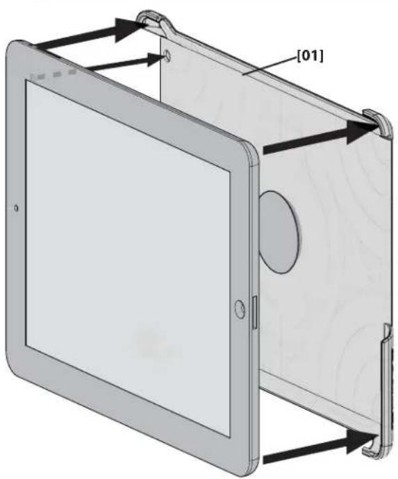
Install iPad® in Holder
Press the iPad ^® into the holder [01] making sure the corners of the holder [01] fit over the corners of the iPad ^® and that the iPad ^® is secure.
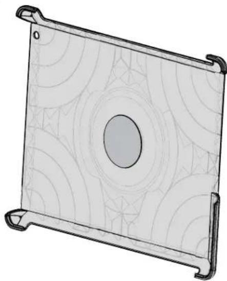
natural_image
3D diagram of a tablet device with labeled components, showing front and side views (no text or symbols beyond labels)Attach Holder to Wall Plate
Place the center ring of the holder [01] onto the mounted wall plate [02]. The holder [01] will magnetically attach.
▲ WARNING: Do not attach the holder [01] to the wall plate [02] unless the wall plate is mounted to a wall. Separation would be difficult and could damage the holder.
![[01] [02]](/content/2026/04/673686/images/14b567dc63fbf5b4e9333d491e582a1433c26eb634ca0c9f3793010c1d18f497.jpg)
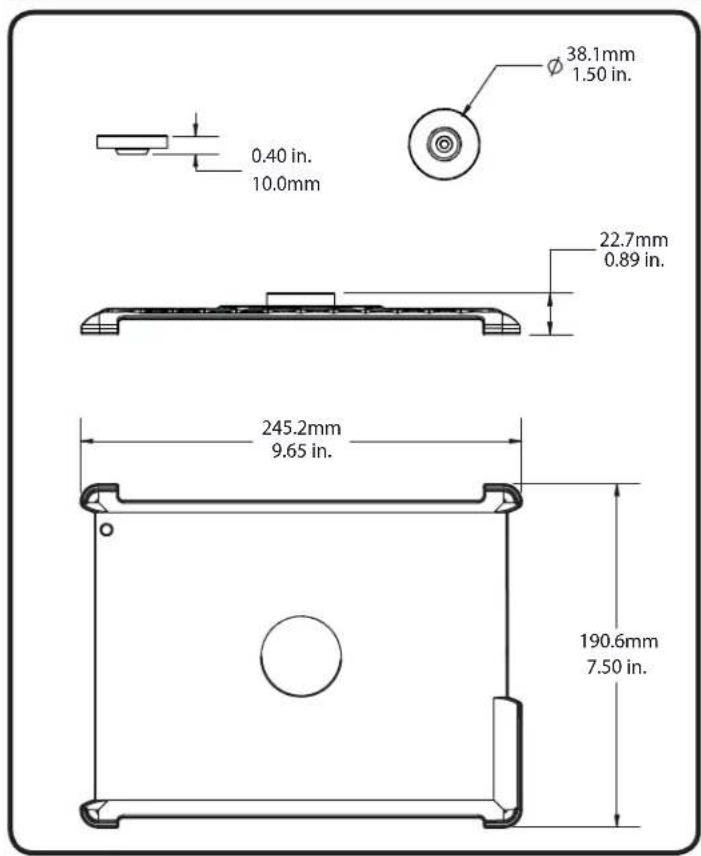
To Remove Holder from Wall Plate Specifications
![To remove the holder from the wall plate, twist the holder [01] horizontally or vertically until it releases from the wall plate [02]. [01] [02]](/content/2026/04/673686/images/5f73f800161637b2dc897ac8eaefa295ea6059e8cbc8fe4247736ac6b2b9915d.jpg)
Français
CONSIGNES DE SÉCURITÉ IMPORTANTES – CONSERVEZ CES INSTRUCTIONS – VEUILLEZ LIRE ATTENTIVEMENT LE MANUEL AVANT D'UTILISER CE PRODUIT
Milestone AV Technologies and its affiliated corporations and subsidiaries (collectively, "Milestone"), intend to make this manual accurate and complete. However, Milestone makes no claim that the information contained herein covers all details, conditions, or variations. Nor does it provide for every possible contingency in connection with the installation or use of this product. The information contained in this document is subject to change without notice or obligation of any kind. Milestone makes no representation of warranty, expressed or implied, regarding the information contained herein. Milestone assumes no responsibility for accuracy, completeness or sufficiency of the information contained in this document.