FCR 28120 E - Electric water heater STIEBEL ELTRON - Free user manual and instructions
Find the device manual for free FCR 28120 E STIEBEL ELTRON in PDF.
| Product type | Electric water heater (heating element for tank) |
| Brand | Stiebel Eltron |
| Model | FCR 28120 E |
| Rated power | 12 kW (single power) |
| Rated voltage | 400 V (3/PE) |
| Frequency | 50 Hz |
| Temperature setting range | 35 °C to 85 °C (factory setting 60 °C) |
| Max. permissible pressure | 1.0 MPa |
| Suitable tank volume | 600 to 1500 liters |
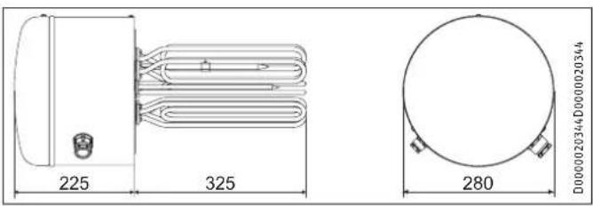
| Minimum tank diameter | 450 mm |
| Flange outer diameter | 280 mm |
| Immersion depth | 325 mm |
| Weight | 12 kg |
| Protection rating | IP24 |
| Main functions | Electric heating of domestic hot water or heating water; single and double power modes (with off-peak contactor and rapid heating) |
| Maintenance and cleaning | Periodic descaling of heating element; checking safety group; regular operation of safety valve |
| Safety | Safety limiter (manual reset); 30 mA residual current circuit breaker mandatory; integrated frost protection |
| Spare parts and repairability | Replaceable heating element and protection tube; accessible thermostat and safety limiter |
| General information | Horizontal mounting in domestic hot water tank or buffer tank; fixed electrical connection (laid cable); safety group required |
Frequently Asked Questions - FCR 28120 E STIEBEL ELTRON
User questions about FCR 28120 E STIEBEL ELTRON
0 question about this device. Answer the ones you know or ask your own.
Ask a new question about this device
Download the instructions for your Electric water heater in PDF format for free! Find your manual FCR 28120 E - STIEBEL ELTRON and take your electronic device back in hand. On this page are published all the documents necessary for the use of your device. FCR 28120 E by STIEBEL ELTRON.
USER MANUAL FCR 28120 E STIEBEL ELTRON
- General information 16
1.1 Safety instructions 16
1.2 Other symbols in this documentation 17
1.3 Units of measurement 17 - Safety 17
2.1 Intended use 17
2.2 General safety instructions 17
2.3 Testmark 17 - Appliance description 17
- Settings 18
4.1 Temperature 18
4.2 Rapid heat-up in dual circuit operation 18 - Cleaning, care and maintenance 18
- Troubleshooting 18
INSTALLATION
- Safety 19
7.1 General safety instructions 19
7.2 Instructions, standards and regulations 19
7.3 Water connection and safety assembly 19 - Appliance description 19
8.1 Standard delivery 19
8.2 Accessories 19 - Installation 19
9.1 Electrical connection 20 - Commissioning 20
10.1 Initial start-up 20
10.2 Recommissioning 21 - Settings 21
11.1 Temperature 21 - Troubleshooting 21
- Maintenance 21
13.1 Checking the safety assembly 21
13.2 Cleaning and descending the appliance 21
13.3 Replacing the heating elements and protective pipe 21 - Specification 22
14.1 Dimensions,immersion depths and connections 22
14.2 Wiring diagrams and terminals 23
14.3 Specification table 25
GUARANTEE
ENVIRONMENT AND RECYCLING
SPECIAL INFORMATION
- The appliance may be used by children over 3 years of age and persons with reduced physical, sensory or mental capabilities or a lack of experience and expertise, provided that they are supervised or they have been instructed on how to use the appliance safely and have understood the potential risks. Children aged 3 to 8 years may only operate the tap connected to the appliance. Children must never play with the appliance. Cleaning and user maintenance must not be carried out by children without supervision.
- The connection to the power supply is only possible as a permanent connection with a permanently installed electric cable. Ensure the appliance can be separated from the power supply by an isolator that disconnects all poles with at least 3mm contact separation.
- Secure the appliance as described in chapter "Installation / Installation".
- Fill the cylinder with water before switching on the appliance.
- The appliance may only be installed in cylinders that are fitted with metal water inlet and outlet pipes.
-
Metal parts of the cylinder that can be touched and that are in contact with water must be permanently and reliably connected to the protective conductor.
If an indirect coil is installed in the same cylinder, limit the maximum temperature for this appliance to the maximum temperature for the flanged immersion heater. This prevents the tempering device of the flanged immersion heater from responding. -
Information on the volume range of the cylinder, the volume above the heating element and the installation position can be found in chapter "Specification / Technical data table". Install a type-tested safety valve in the cold water inlet of the cylinder. Please note that, depending on the supply pressure, you may also need a pressure reducing valve.
- Size the drain so that water can drain off unimpeded when the safety valve is fully opened.
- Fit the drain pipe of the safety valve with a constant fall in a room free from the risk of frost.
- The drain connection of the safety valve must remain open to the atmosphere.
- Install a residual current device (RCD).
OPERATION
1. General information
The chapter "Operation" is intended for appliance users and qualified contractors.
The chapter "Installation" is intended for qualified contractors.

Notice
Read these instructions carefully before using the appliance. Keep them in a safe place.
Pass on the instructions to a new user if required.
1.1 Safety instructions
1.1.1 Structure of safety instructions

SIGNAL WORD Type of risk
Lists possible consequences of a failure to observe the safety instructions.
Indicates steps to prevent the risk.
1.1.2 Symbols, type of risk
Symbol Type of risk

Injury

Electrocution

Burns
(burns, scalding)
1.1.3 Signal words
| SIGNAL WORD | Meaning |
| DANGER | Failure to observe this information will result in serious injury or death. |
| WARNING | Failure to observe this information may result in serious injury or death. |
| CAUTION | Failure to observe this information may result in moderate or minor injury. |
1.2 Other symbols in this documentation

Notice
General information is indicated by the adjacent symbol.
Read these texts carefully.
Symbol Meaning

Property damage
(appliance damage, consequential losses and environmental pollution)

Appliance disposal
This symbol indicates that you have to do something. The action you need to take is described step by step.
1.3 Units of measurement

Notice
All measurements are given in mm unless stated otherwise.
2. Safety
2.1 Intended use
The appliance is intended for installation in cylinders in a pressure-tested heating or DHW heating system.
The appliance is intended for domestic use. It can be used safely by untrained persons. The appliance can also be used in non-domestic environments, e.g. in small businesses, as long as it is used in the same way.
Any other use beyond that described shall be deemed inappropriate. Observation of these instructions and of the instructions for any accessories used is also part of the correct use of this unit.
Using the appliance for heating fluids other than water or for water supplemented with chemicals, such as brine, is also deemed inappropriate.
2.2 General safety instructions

WARNING Electrocution
Never spray the appliance with water or other liquids.

WARNING Burns
There is a risk of scalding at outlet temperatures in excess of 43^ .

WARNING Injury
The appliance may be used by children aged 3 and up and persons with reduced physical, sensory or mental capabilities or a lack of experience and know-how, provided that they are supervised or they have been instructed on how to use the appliance safely and have understood the resulting risks. Children aged 3 to 8 years may only operate the tap connected to the appliance. Children must never play with the appliance. Cleaning and user maintenance must not be carried out by children without supervision.

Property damage
Condensate can drip from the appliance.
Never store objects below the appliance.

Notice
The appliance is pressurised.
During the heat-up process, expansion water will drip from the safety valve.
If water continues to drip once heat-up is complete, please inform a qualified contractor.
2.3 Test mark
See type plate on the appliance.
3. Appliance description
The appliance electrically heats DHW and heating water. Depending on the type of appliance, the temperature can be adjusted by yourself or a qualified contractor using the temperature selector. Once the selected temperature has been reached the appliance shuts down. If required, the appliance automatically restarts in single circuit operation and in dual circuit operation during off-peak tariff periods / enable times.
The appliance is protected against frost so long as the power supply is guaranteed, even on the "cold" temperature setting. The appliance switches on in good time and heats the water. The tap and the mains water supply line are not protected against frost by the appliance.
4. Settings
4.1 Temperature
Appliance type with temperature selector inside the control panel
The temperature can be freely selected by a qualified contractor (see chapter "Installation / Settings").
Factory setting: 60^
4.2 Rapid heat-up in dual circuit operation
For appliance types with dual circuit operation, the qualified contractor can install a button to control the rapid heat-up function remotely. If required, you can switch this on. The rapid heat-up function switches off when the selected temperature has been reached and will not switch on again automatically.
5. Cleaning, care and maintenance
Have the electrical safety of the appliance regularly checked by a qualified contractor.
Scaling
Almost every type of water will deposit limescale at high temperatures. Limescale will settle inside the appliance and affect its function and service life. The heating elements must therefore be descaled from time to time. A qualified contractor who is aware of the local water quality will tell you when the next service is due.
-
Check the taps regularly. Limescale deposits at the tap outlets can be removed using commercially available descaling agents.
Regularly activate the safety valve to prevent it from becoming blocked e.g. by limescale deposits. -
Troubleshooting
| Fault Cause Remedy | ||
| The water does not heat up. | There is no power. | Check the fuses / MCBs in your fuse box / distribution board. |
| The temperature is incorrectly adjusted. | Check the temperature setting. | |
| The flow rate is low. | The aerator in the taps or shower heads is dirty or scaled-up. | Clean or descale the aerator or shower head. |
| Water drips from the safety assembly after heating has stopped. | The valve seat is contaminated. | Depressurise and isolate the appliance from the power supply. Contact a qualified contractor. |
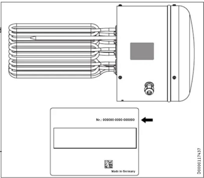
If you cannot remedy the fault, notify a qualified contractor. To facilitate and speed up your enquiry, please provide the serial number from the type plate (no. 000000-0000-000000):
INSTALLATION
7. Safety
Only a qualified contractor should carry out installation, commissioning, maintenance and repair of the appliance.
7.1 General safety instructions
We guarantee trouble-free functional and operational reliability only if original accessories and spare parts intended for the appliance are used.
7.2 Instructions, standards and regulations

Notice
Observe all applicable national and regional regulations and instructions.
7.3 Water connection and safety assembly

Notice
Carry out all water connection and installation work in accordance with regulations.
The water inlet and outlet pipes of the cylinder in which the appliance is installed must be made of metal.
Metal parts of the cylinder that can be touched and that are in contact with water must be permanently and reliably connected to the protective conductor.

Notice
A safety valve is required.
The max. permissible pressure must not be exceeded (see chapter "Specification / Data table" and cylinder specification).
f Install a type-tested safety valve in the cold water inlet. Please note that, depending on the supply pressure, you may also need a pressure reducing valve.
f Size the drain so that water can drain off unimpeded when the safety valve is fully opened.
f Fit the drain pipe of the safety valve with a constant fall in a room free from the risk of frost.
f The drain connection of the safety valve must remain open to the atmosphere.
8. Appliance description
8.1 Standard delivery
The following are delivered with the appliance:
PG29 cable gland
Fixing screws, corrugated washers
- Jumpers
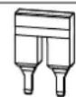
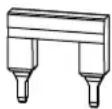

D0000119253
8.2 Accessories
Required accessories
Safety assemblies and pressure reducing valves are available to suit the prevailing supply pressure. These type-tested safety assemblies protect the appliance against impermissible excess pressure.
Additional accessories
A mating flange is available as an accessory.
9. Installation

Notice
For the installation of the appliance, the cylinder must be fitted with a mating flange (see chapter "Appliance description / Accessories").

Notice
The control panel must not be thermally insulated to prevent any excessively high temperatures from occurring inside the control panel.
The condensate drain aperture in the control panel must remain open while the cylinder is thermally insulated so that any condensate that occurs can drip off freely.
f Observe the required torque values during installation (see chapter "Specification / Data table").
f Always install the appliance horizontally with the cable entries facing downwards.
f Always install the appliance with heating elements and a protective pipe arranged in parallel. For this, use the screws supplied. Realign the components where necessary.
9.1 Electrical connection

WARNING Electrocution
Carry out all electrical connection and installation work in accordance with relevant regulations.

WARNING Electrocution
The connection to the power supply is only possible as a permanent connection with a permanently installed electric cable. Ensure the appliance can be separated from the power supply by an isolator that disconnects all poles with at least 3mm contact separation.

WARNING Electrocution
Ensure that the appliance is connected to the earth conductor.

Property damage
Install a residual current device (RCD).

Property damage
Observe the type plate. The specified voltage must match the mains power supply.

Property damage
Never switch on the power before filling the appliance.
Remove the three screws from the cover panel cover.
Remove the control panel lid.
- Select a cable of the cross-sectional area suited to the load the appliance.
Prepare the power cable.
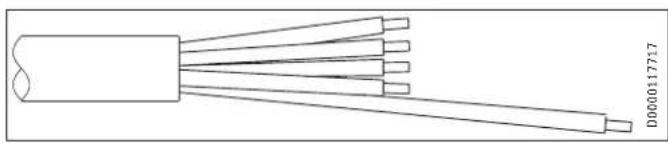
- Ensure that the protective conductor is longer than the other conductors.
Feed the power cable through the cable entry into the panel. The PG21 cable gland for cable diameters up to 18mm is prefitted.
For cable diameters larger than 18mm first replace the PG2 cable gland with the PG29 cable gland supplied.
Connect the required load to the terminal block in the appliance in accordance with the wiring diagrams.
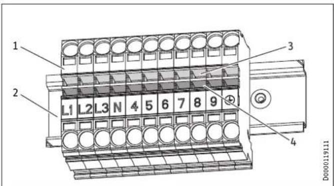
1 Terminal block
2 Top-hat rail
3 Upper row of terminals
4 Lower row of terminals
Example with 2 jumpers:
Information on the connection options can be found in chapter "Specification / Wiring diagrams and connections")
Refit the control panel cover and secure it with the screws.
- Appliance type with dual circuit operation: Use a ballpoint pen to mark the selected connected load and voltage on the type plate.
10. Commissioning
10.1 Initial start-up
Fill the system with water.
Property damage
Boiling dry destroys the thermostat, which must then be replaced. The high limit safety cut-out must be reset.
Property damage
If an indirect coil is installed in the same cylinder, limit the maximum temperature for this appliance to the maximum temperature for the flanged immersion heater. This prevents the tempering device of the flanged immersion heater from responding.
Switch the appliance on electrically.
INSTALLATION
Settings
Appliance handover
Explain the functions of the appliance to the user. Show the user how to operate the appliance.
Make users aware of potential dangers.
Hand over these instructions.
10.2 Recommissioning
See chapter "Initial start-up".
11. Settings
11.1 Temperature
Appliance type with temperature selector inside the control panel
The temperature is variably adjustable.
Factory setting 60^ (the temperature selector clicks into place at this setting).
12. Troubleshooting
| Fault Cause Remedy | ||
| The water does not heat up. | The high limit safety cut-out has responded because the controller is faulty. | Replace the thermostat and press the high limit safety cut-out reset button. |
| The high limit safety cut-out has responded because the temperature has fallen below -15 °C. | Press the reset button. | |
| A heating element is faulty. | Replace the heating element or flanged immersion heater. | |
| The high limit safety cut-out has responded because an indirect coil in the same cylinder is set too high. | Limit the maximum temperature of the indirect coil. | |
| The safety valve drips when heating is switched off. | The valve seat is contaminated. | Clean the valve seat. |
High limit safety cut-out reset button
13. Maintenance

WARNING Electrocution
Before any work on the appliance, disconnect all poles from the power supply.
13.1 Checking the safety assembly
Check the safety assembly regularly.
13.2 Cleaning and descending the appliance
Never use descending pumps.
Only descale the flanged immersion heater after dismantling and never treat the cylinder surface or signal anode with descending agents.
For the torque of the flange screws, see chapter "Specification / Dimensions and connections"
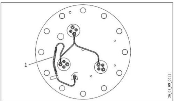
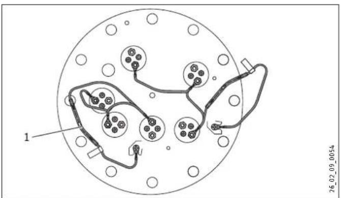
13.3 Replacing the heating elements and protective pipe
Install the electrically insulated heating element and protective pipes into the flange plate.

Property damage
The corrosion protection resistor must not be damaged or removed during maintenance work.
3 Heating element

1 Corrosion protection resistor (390 Ω)
6 heating elements

1 Corrosion protection resistor (390)
Connect the heating elements with the cylinder via the corrosion resistor.
The corrosion resistor acts to balance the potential and prevents power leakage corrosion on the heating elements.
1 Protective pipes
2 Heating element
3 Flange plate
14. Specification
14.1 Dimensions, immersion depths and connections
FCR 28
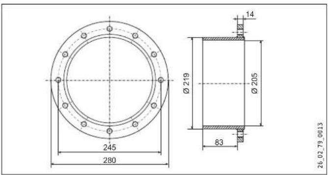
Mating flange FCR 28
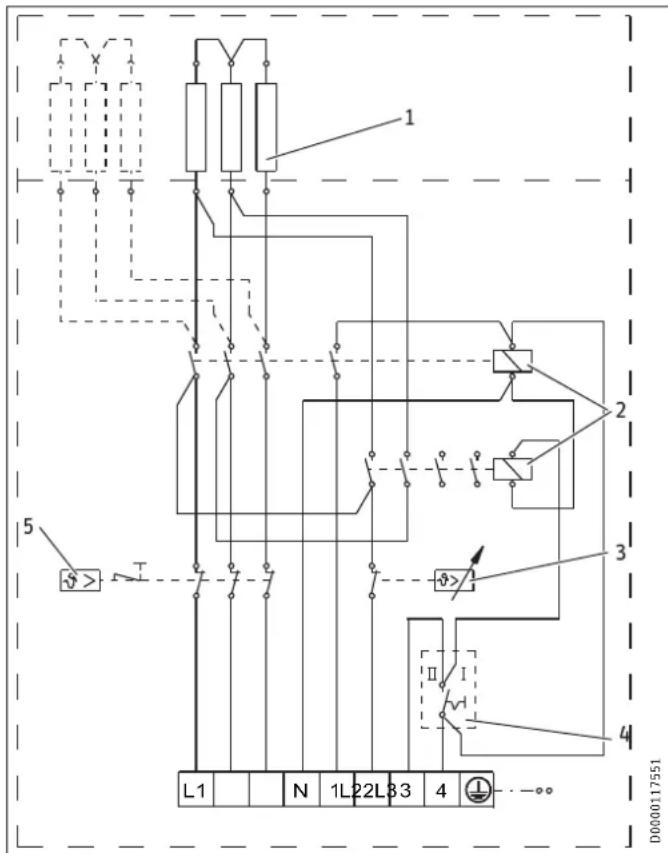
14.2 Wiring diagrams and terminals
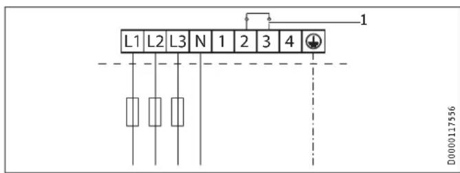
14.2.1 Single circuit operation
FCR 28/120 E, part number 000694
FCR 28/180 E, part number 000695
6,9,12,18 kW, 3/PE ~ 400 V
1 Heating element
6 kW connected load: 3 x 2 kW
9 kW connected load: 3 x 3 kW
12 kW connected load: 6 x 2 kW
18 kW connected load: 6 x 3 kW
2 Contactor
3 High limit safety cut-out
4 Temperature controller
Connection example for single circuit operation with power-OFF contact
1 Power-OFF contact, installed by the qualified contractor
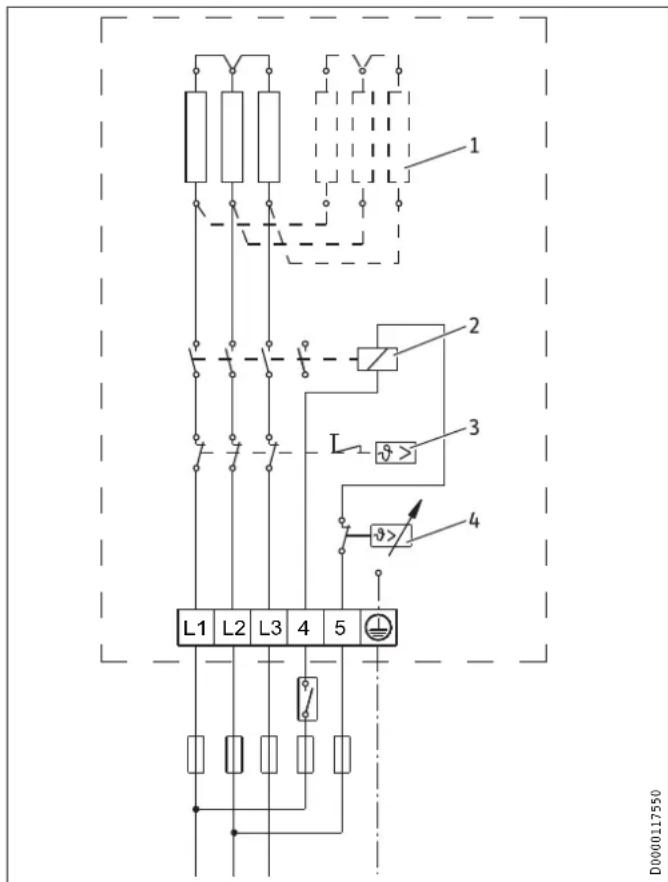
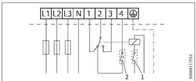
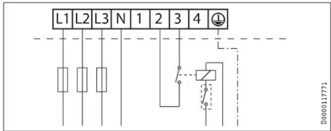
14.2.2 Dual circuit / single circuit operation 3/N/PE 400V
FCR 28/120, part number 071332
FCR 28/120 CrNi, part number 234503
FCR 28/180, part number 071333
1 Heating element
12 kW connected load: 3 × 4 kW
18 kW connected load: 6 x 3 kW
2 Contactor
3 Temperature controller
4 Circuit breaker I / II
5 High limit safety cut-out
Connection example for dual circuit operation
FCR 28/120, part number 071332
FCR 28/120 CrNi, part number 234503
6/12 kW Circuit breaker I
12/12 kW Circuit breaker II
FCR 28/180, part number 071333
9/18 kW Circuit breaker I
18/18 kW Circuit breaker II
Version 1:
1 Power-OFF contact, installed by the qualified contractor
2 Button for controlling the rapid heat-up function remotely, installed by the qualified contractor
3 Jumper
During the economy tariff period (power-OFF), it is possible to switch on the rapid heat-up function (peak tariff).
Version 2:
1 Power-OFF contact, installed by the qualified contractor
2 Button for controlling the rapid heat-up function remotely, installed by the qualified contractor
During the economy tariff period (power-OFF), the rapid heat-up function (peak tariff) can only be switched on if the circuit breaker is in position II.
Connection example for dual meter reading
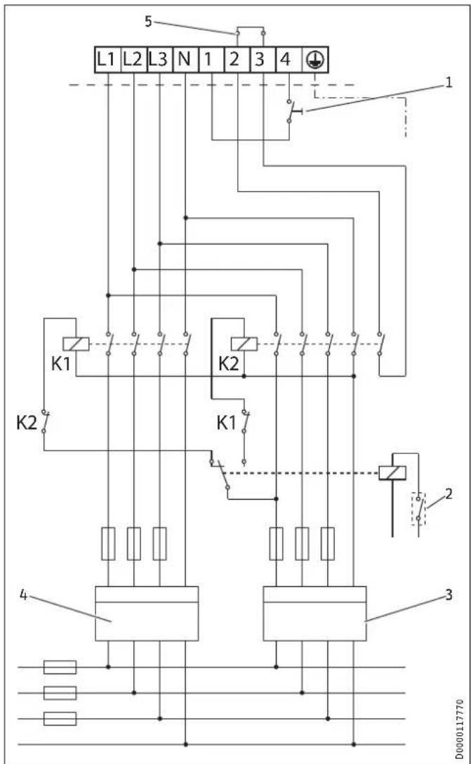
K1 Contactor 1, installed by the qualified contractor
K2 Contactor 2, installed by the qualified contractor
1 Button for controlling the rapid heat-up function remotely, installed by the qualified contractor
2 Power-OFF contact, installed by the qualified contractor
3 Off-peak tariff
4 Peak tariff
5 Jumper
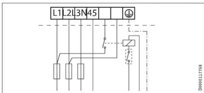
Connection example for single circuit operation
FCR 28/120, part number 071332
FCR 28/120 CrNi, part number 234503
6 kW Circuit breaker I
12 kW Circuit breaker II
FCR 28/180, part number 071333
9 kW Circuit breaker I
18 kW Circuit breaker II
Without power-OFF contact:
1 Jumper
With power-OFF contact:
1 Power-OFF contact, installed by the qualified contractor
14.3 Specification table
| FCR 28/120 FCR 28/120 CrNi FCR 28/120 E FCR 28/180 FCR 28/180 E | ||||||
| 071332 | 234503 | 000694 | 071333 | 000695 | ||
| Electrical data | ||||||
| Connected load ~ 400 V | kW | 6/12 | 6/12 | 12 | 9/18 | 18 |
| Connected load ~ 380 V | kW | 10,8 | 16,4 | |||
| Rated voltage | V | 400 | 400 | 400 | 400 | 400 |
| Phases | 3/N/PE | 3/N/PE | 3/PE | 3/N/PE | 3/PE | |
| Frequency | Hz | 50 | 50 | 50 | 50 | 50 |
| Single circuit operating mode | X | X | X | X | X | |
| Dual circuit operating mode | X | X | X | |||
| Application limits | ||||||
| Temperature setting range | °C | 35-85 | 35-85 | 35-85 | 35-85 | 35-85 |
| Max. permissible pressure | MPa | 1,0 | 1,0 | 1,0 | 1,0 | 1,0 |
| For use in | DHW cylinders,buffer cylinders | DHW cylinders,buffer cylinders | DHW cylinders,buffer cylinders | DHW cylinders,buffer cylinders | DHW cylinders,buffer cylinders | |
| Volume range of the cylinder | l | 600-1500 | 600-1500 | 600-1500 | 600-1500 | 600-1500 |
| Volume above the heating element (max.) | l | 1000 | 1000 | 1000 | 1000 | 1000 |
| Installation position | Horizontal | Horizontal | Horizontal | Horizontal | Horizontal | |
| Minimum cylinder diameter | mm | 450 | 450 | 450 | 450 | 450 |
| Versions | ||||||
| IP rating | IP 24 | IP 24 | IP 24 | IP 24 | IP 24 | |
| Dimensions | ||||||
| Flange external diameter | mm | 280 | 280 | 280 | 280 | 280 |
| Immersion depth | mm | 450 | 450 | 325 | 450 | 325 |
| Torque | Nm | 80 | 80 | 80 | 80 | 80 |
| Weights | ||||||
| Weight | kg | 12 | 12 | 12 | 13 | 14 |
Guarantee
The guarantee conditions of our German companies do not apply to appliances acquired outside of Germany. In countries where our subsidiaries sell our products a guarantee can only be issued by those subsidiaries. Such guarantee is only granted if the subsidiary has issued its own terms of guarantee. No other guarantee will be granted.
We shall not provide any guarantee for appliances acquired in countries where we have no subsidiary to sell our products. This will not affect warranties issued by any importers.
Environment and recycling
- Dispose of the appliances and materials after use in accordance with national regulations.

If a crossed-out waste bin is pictured on the appliance, take the appliance to your local waste and recycling centre or nearest retail take-back point for reuse and recycling.

PAP
This document is made of recyclable paper.
Dispose of the document at the end of the appliance's life cycle in accordance with national regulations.
REMARQUESPARTICULIERES
UTILISATION
1 Résistance anti-corrosion (390 Ω)
6 corps de chauffe
1 Résistance anti-corrosion (390 Ω)
FCR 28/120 E, ref. cde 000694
FCR 28/180 E, ref. cde 000695
6,9,12,18 kW, 3/PE ~ 400 V
FCR 28/120, ref. cde 071332
FCR 28/120 CrNi, ref. cde 234503
FCR 28/180, ref. cde 071333
FCR 28/120, ref. cde 071332
FCR 28/120 CrNi, ref. cde 234503
FCR 28/180, ref. cde 071333
FCR 28/120, ref. cde 071332
FCR 28/120 CrNi, ref. cde 234503
6 kW Disjoncteur I
FCR 28/180, ref. cde 071333
9 kW Disjoncteur I
WAARSCHUWING verbranding
Instalujte proudovychranic (RCD).

Vécné skody
Dodrzejude uvedene na typovem stitku. Uvedene napeti se musi shodovat se sifovym napetim.

Vecne skody
Pristoj prd plnem nepripojte k elektricke siti.