DHBE 13 SLi electronic - Electric water heater STIEBEL ELTRON - Free user manual and instructions
Find the device manual for free DHBE 13 SLi electronic STIEBEL ELTRON in PDF.
| Product type | Electronic instantaneous electric water heater |
| Dimensions (H x W x D) | 478 x 225 x 105 mm |
| Weight | 3.6 kg |
| Power supply | Three-phase 3/PE ~ 380-415 V, 50/60 Hz |
| Nominal power | 13.5 kW (at 400 V) |
| Nominal current | 19.5 A |
| Electrical protection | 20 A |
| Protection rating | IP 25 (recessed), IP 24 (surface-mounted) |
| Temperature range | 30 °C to 60 °C (continuous adjustment) |
| Temperature limitation | Possible at 43 °C (anti-scald protection) |
| Maximum admissible pressure | 1 MPa |
| Activation flow rate | > 3 L/min |
| Nominal flow rate | 3.9 L/min (pressure drop 0.11 MPa) |
| Nominal capacity | 0.4 L |
| Heating system | Bare wire with pressure-resistant synthetic sheath |
| Main functions | Electronic temperature regulation, air detector, diagnostic LEDs |
| Safety | Safety pressure switch, STB safety limiter, frost protection |
| Hydraulic connection | G 1/2 A (male thread) |
| Maintenance | Cleaning the filter, descaling tap nozzles |
| Materials | Cover and back panel in synthetic material, white |
| Warranty | According to conditions of country of purchase |
Frequently Asked Questions - DHBE 13 SLi electronic STIEBEL ELTRON
User questions about DHBE 13 SLi electronic STIEBEL ELTRON
0 question about this device. Answer the ones you know or ask your own.
Ask a new question about this device
Download the instructions for your Electric water heater in PDF format for free! Find your manual DHBE 13 SLi electronic - STIEBEL ELTRON and take your electronic device back in hand. On this page are published all the documents necessary for the use of your device. DHBE 13 SLi electronic by STIEBEL ELTRON.
USER MANUAL DHBE 13 SLi electronic STIEBEL ELTRON
BEDIENUNG UND INSTALLATION OPERATING AND INSTALLATION UTILISATION ET INSTALLATION GEBRUIK EN INSTALLATIE OBSŁUGA I INSTALACJA OBSLUHA A INSTALACE
Elektronisch geregelter Durchlauferhitzer | Electronically controlled instantaneous water heater | Chauffe-eau instantanés à régulation électronique | Elektronisch geregelde doorstromer | Elektronicznie regulowany przepływowy ogrzewacz wody | Elektronicky regulovaný průtokový ohřívač
text_image
1000000 M M M MSTIEBEL ELTRON
BESONDERE HINWEISE
BEDIENUNG
text_image
Technical diagram of a bathroom sink with labeled components and directional arrows indicating flow or movement.text_image
2 1 26_02_02_0845text_image
2 1 26.02_02_0820text_image
Technical diagram of an electrical control unit with labeled components and a magnified view showing internal structure and power connections.10. Montage
Standardmontage
text_image
Technical diagram showing mechanical assembly steps with labeled components and directional arrowsnatural_image
Technical diagram of a mechanical assembly with two views showing internal components and directional arrows (no text or symbols)4,0 l/min = rosa
7,5 l/min = blau
8,5 l/min = grün
natural_image
Technical diagram of an industrial machine assembly with internal components and two circular insets showing close-ups (no text or labels)natural_image
Mechanical assembly diagram showing two stages of a valve mechanism with rotating components and directional arrows (no text or symbols)natural_image
Technical diagram of a mechanical assembly with internal components and directional arrows (no text or symbols)text_image
on ≥ 60 s on D0000051946text_image
Technical diagram showing mechanical assembly with labeled parts and a magnified view of tool pathtext_image
1 2 3 4 26_02_02_0821natural_image
Mechanical component diagram with mounting holes and a central shaft (no text or symbols)26_02_02_0815_
natural_image
Technical diagram of a mechanical assembly inside a transparent enclosure, showing internal components and a magnified inset with an arrow indicating direction (no text or symbols present)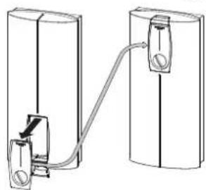
natural_image
Diagram of two cylindrical containers connected by a cable, showing internal components and connection (no text or symbols)26_02_02_0817
text_image
Technical diagram showing two views of an electronic device with labeled components and wiring connectionstext_image
1 2 3 4 L1' L2' L3' L P 3 85_02_02_0005text_image
2 1 L L L 1> 85_02_02_0003_- General information 22
1.1 Safety instructions 22
1.2 Other symbols in this documentation 22
1.3 Units of measurement 22 - Safety 22
2.1 Intended use 22
2.2 General safety instructions 22
2.3 Test symbols 23 - Appliance description 23
- Operation 23
4.1 Recommended settings 23
4.2 Temperature limit / Anti-scalding protection ____ 23 - Cleaning, care and maintenance 24
- Troubleshooting 24
INSTALLATION
- Safety 25
7.1 General safety instructions 25
7.2 Instructions, standards and regulations 25 - Appliance description 25
8.1 Standard delivery 25
8.2 Accessories 25 - Preparations 26
9.1 Installation site 26
9.2 Water installation 26
9.3 Appliance with adjustable connected load 27 - Installation 27
10.1 Standard installation 27
10.2 Completing the installation 29 - Commissioning 29
11.1 Initial start-up 29
11.2 Recommissioning 30 - Shutdown 30
-
Installation options 30
13.1 Electrical connection from above on unfinished walls_30
13.2 Electrical connection on finished walls 30
13.3 Large conductor cross-section for electrical connection from below 30
13.4 Connecting a load shedding relay 31
13.5 Water installation on finished walls 31
13.6 Water installation on finished walls with solder / compression fitting 31
13.7 Water installation on finished walls; fitting the appliance cover 31
13.8 Fitting the base part of the back panel with threaded fittings on finished walls 32
13.9 Wall mounting bracket when replacing an appliance 32
13.10 Installation with offset tiles 32
13.11 Pivoting appliance cover 32
13.12 Temperature limit / Anti-scalding protection ____ 33 -
Troubleshooting 34
- Maintenance 35
- Specification 35
16.1 Dimensions and connections 35
16.2 Wiring diagram 35
16.3 DHW output 36
16.4 Application areas / conversion table 36
16.5 Pressure drop 36
16.6 Fault conditions 36
16.7 Country-specific approvals and certifications: Germany37
16.8 Details on energy consumption 37
16.9 Data table 38
GUARANTEE
ENVIRONMENT AND RECYCLING
SPECIAL INFORMATION
- The appliance may be used by children aged 8 and older and persons with reduced physical, sensory or mental capabilities or a lack of experience and know-how, provided that they are supervised or they have been instructed on how to use the appliance safely and have understood the resulting risks. Children must never play with the appliance. Children must never clean the appliance or perform user maintenance unless they are supervised.
- Risk of burns: The tap can reach temperatures in excess of 60 °C .
- Ensure the appliance can be separated from the power supply by an isolator that disconnects all poles with at least 3 mm contact separation.
- Secure the appliance as described in chapter "Installation / Installation".
- Observe the maximum permissible pressure (see chapter "Installation / Specification / Data table").
- Drain the appliance as described in chapter "Installation / Maintenance / Draining the appliance".
OPERATION
1. General information
The chapters "Special Information" and "Operation" are intended for both the user and qualified contractors.
The chapter "Installation" is intended for qualified contractors.

Note
Read these instructions carefully before using the appliance and retain them for future reference. Pass on the instructions to a new user if required.
1.1 Safety instructions
1.1.1 Structure of safety instructions

KEYWORD Type of risk
Here, possible consequences are listed that may result from failure to observe the safety instructions.
▶ Steps to prevent the risk are listed.
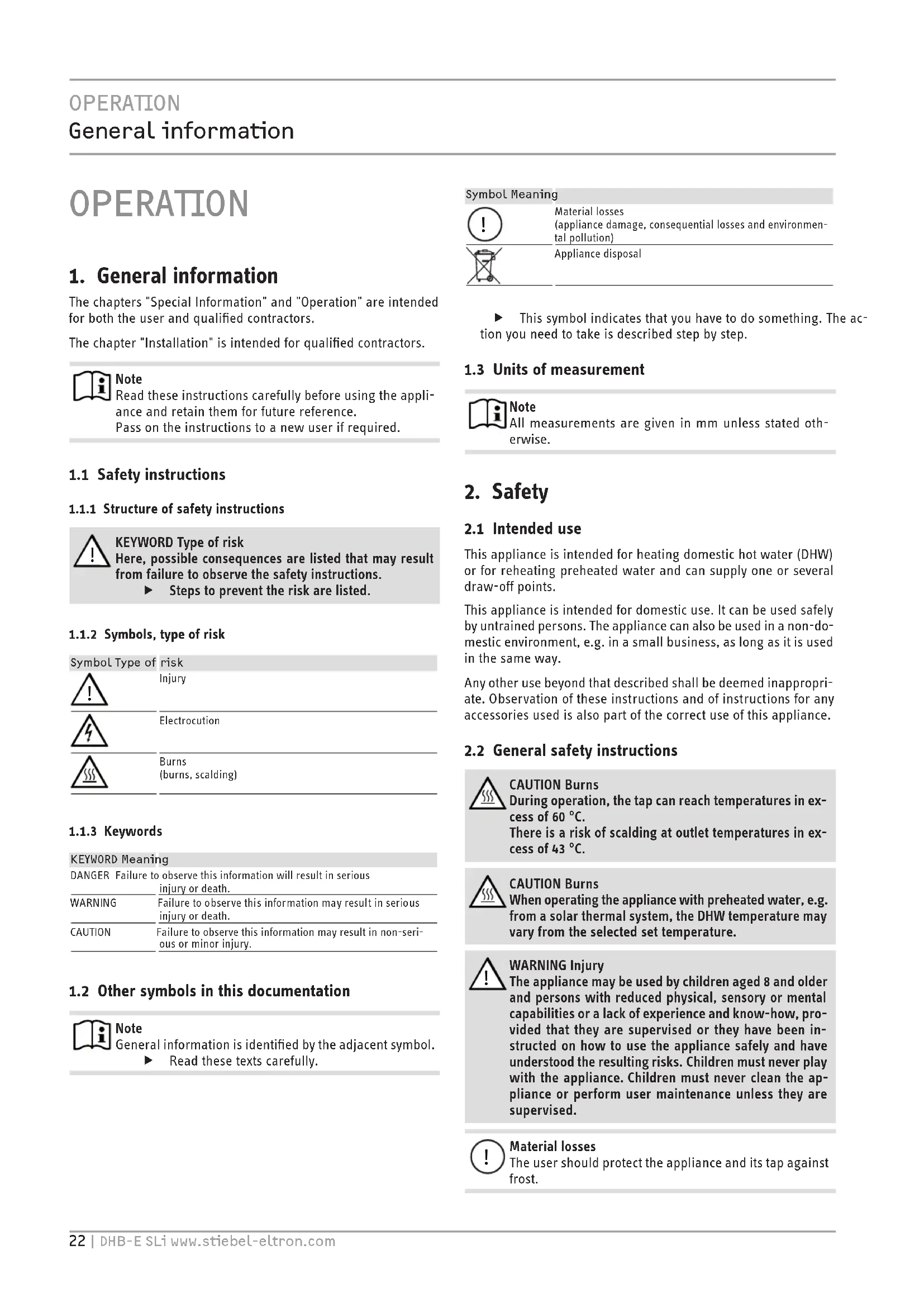
1.1.2 Symbols, type of risk
Symbol Type of risk

Injury

Electrocution

Burns (burns, scalding)
1.1.3 Keywords
KEYWORD Meaning
DANGER Failure to observe this information will result in serious injury or death.
WARNING Failure to observe this information may result in serious injury or death.
CAUTION Failure to observe this information may result in non-serious or minor injury.
1.2 Other symbols in this documentation

Note
General information is identified by the adjacent symbol.
▶ Read these texts carefully.
Symbol Meaning

Material losses
(appliance damage, consequential losses and environmental pollution)

Appliance disposal
This symbol indicates that you have to do something. The action you need to take is described step by step.
1.3 Units of measurement

Note
All measurements are given in mm unless stated otherwise.
2. Safety
2.1 Intended use
This appliance is intended for heating domestic hot water (DHW) or for reheating preheated water and can supply one or several draw-off points.
This appliance is intended for domestic use. It can be used safely by untrained persons. The appliance can also be used in a non-domestic environment, e.g. in a small business, as long as it is used in the same way.
Any other use beyond that described shall be deemed inappropriate. Observation of these instructions and of instructions for any accessories used is also part of the correct use of this appliance.
2.2 General safety instructions

CAUTION Burns
During operation, the tap can reach temperatures in excess of 60 °C .
There is a risk of scalding at outlet temperatures in excess of 43^ C.

CAUTION Burns
When operating the appliance with preheated water, e.g. from a solar thermal system, the DHW temperature may vary from the selected set temperature.

WARNING Injury
The appliance may be used by children aged 8 and older and persons with reduced physical, sensory or mental capabilities or a lack of experience and know-how, provided that they are supervised or they have been instructed on how to use the appliance safely and have understood the resulting risks. Children must never play with the appliance. Children must never clean the appliance or perform user maintenance unless they are supervised.

Material losses
The user should protect the appliance and its tap against frost.
2.3 Test symbols
See type plate on the appliance.
3. Appliance description
The electronically controlled instantaneous water heater maintains a constant outlet temperature up to its output limit, irrespective of the inlet temperature.
The appliance heats the water directly at the draw-off point, as soon as you turn on the hot water tap. The short pipe runs ensure that energy and water losses are minimal.
For the start flow rate, see chapter "Installation / Specification / Data table, On".
The DHW output depends on the cold water temperature, the heating output, the flow rate and the selected set temperature.
Water will not be reheated if the maximum inlet temperature for reheating is exceeded.
DHW temperature
The DHW outlet temperature can be variably adjusted.
Temperature limit / Anti-scalding protection
The maximum outlet temperature for the appliance can be limited to 43 °C. For this, contact your local heating contractor.
Heating system
The bare wire heating system has a pressure-tested plastic casing. The heating system is suitable for (both) soft and hard water and is largely resistant to scale build-up. This heating system ensures rapid and efficient DHW availability.

Note
The appliance is equipped with an air detector that largely prevents damage to the heating system. If, during operation, air is drawn into the appliance, the appliance shuts down for one minute, thereby protecting the heating system.
4. Operation
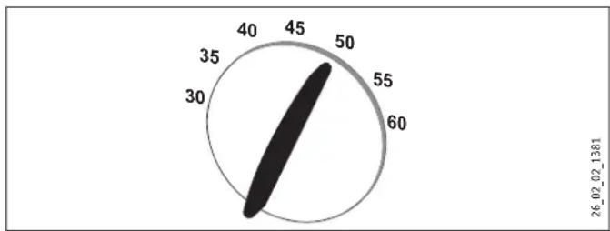
gauge
| Value | |---| | 50 | | 60 |▶ Turn the temperature selector to the required position.
If the outlet temperature fails to reach the required level with the tap fully open and the temperature selector set to maximum, then more water is flowing through the appliance than can be heated by the heating element.
▶ Reduce the flow rate at the tap.
4.1 Recommended settings
Thermostatic valve
If the appliance is being operated with a thermostatic valve, we recommend setting the temperature on the appliance to maximum. The required temperature can then be set at the thermostatic valve.
Following an interruption to the water supply

Material losses
To ensure that the bare wire heating system is not damaged following an interruption to the water supply, the appliance must be restarted taking the following steps.
▶ Disconnect the appliance from the power supply by removing the fuses/tripping the MCBs.
▶ Open the tap for one minute until the appliance and its upstream cold water inlet line are free of air.
▶ Switch the mains power back ON again.
4.2 Temperature limit / Anti-scalding protection
The maximum outlet temperature for the appliance can be limited to 43 °C. For this, contact your local heating contractor.
5. Cleaning, care and maintenance
▶ Never use abrasive or corrosive cleaning agents. A damp cloth is sufficient for cleaning the appliance.
▶ Check the taps regularly. Limescale deposits at the tap outlets can be removed using commercially available descaling agents.
6. Troubleshooting
| Problem Cause Remedy | ||
| The appliance will not start despite the DHW valve being fully open. | There is no power. | Check the fuses/MCBs in your fuse box/distribution panel. |
| The aerator in the tap or the shower head is scaled up or contaminated. | Clean and/or descale the aerator or shower head. | |
| When hot water is being drawn off, cold water flows for a short period. | The air sensor detects air in the water and briefly switches the heater off. | The appliance restarts automatically after 1 minute. |
| Required temperature >45 °C is not achieved. | The water supply has been interrupted. | Vent the appliance and the cold water supply line (see chapter "Operation / Recommended settings / Following an interruption to the water supply"). |
| Cold water inlet temperature is >45 °C. | Reduce the cold water inlet temperature. | |
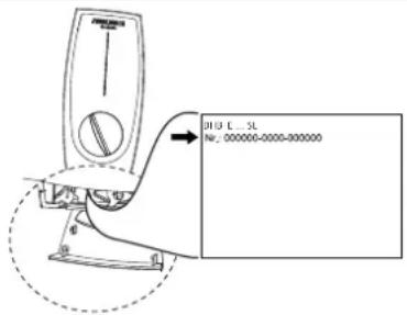
If you cannot remedy the fault, notify your qualified contractor. To facilitate and speed up your request, provide the number from the type plate (000000-0000-000000).
text_image
H10 C. SL No: 000000-0000-000000INSTALLATION
7. Safety
Only a qualified contractor should carry out installation, commissioning, maintenance and repair of the appliance.
7.1 General safety instructions
We guarantee trouble-free function and operational reliability only if original accessories and spare parts intended for the appliance are used.

Material losses
Observe the maximum permissible inlet temperature (see chapter "Installation / Specification / Data table"). Higher temperatures may damage the appliance. The inlet temperature can be limited by means of a central thermostatic valve (see chapter "Installation / Appliance description / Accessories").
7.2 Instructions, standards and regulations

Note
Observe all applicable national and regional regulations and instructions.
- The IP 25 (hoseproof) rating can only be ensured with a correctly fitted cable grommet.
- The specific electrical resistance of the water must not fall below that stated on the type plate. In a linked water network, factor in the lowest electrical resistance of the water (see chapter "Installation / Specification / Data table"). Your water supply utility will advise you of the specific electrical resistance or conductivity of the water.
8. Appliance description
8.1 Standard delivery
The following are delivered with the appliance:
- Wall mounting bracket
- Installation template
- 2 twin connectors
- Cold water 3-way ball shut-off valve
- DHW tee
- Flat gaskets
- Strainer
- Flow limiter
- Plastic profile washer
- Plastic connection pieces / installation aid
- Cap and back panel guides
8.2 Accessories
Taps/valves
- MEKD mono lever kitchen pressure tap
- MEBD mono lever bath pressure tap
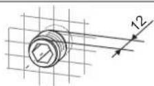
Plug G 12 A
If you use pressure taps for finished walls other than those recommended in the accessories, please use the plugs.
Installation set for finished walls
- Solder fitting - copper pipe for soldered connection ∅ 12 mm
- Compression fitting - copper pipe
- Compression fitting - plastic pipe (suitable for Viega: Sanfix-Plus or Sanfix-Fosta)
Universal mounting frame
- Mounting frame with electrical connections
Pipe assembly for undersink appliances
You will need the undersink installation set if you make the water connections (G 38 A) at the top of the appliance.
Pipe assembly for offset installation
Use this pipe assembly set if you intend to offset the appliance by 90 mm downwards from the water connection.
Pipe assembly for replacing a gas water heater
You will need this pipe assembly set if the existing installation has gas water heater connections (cold water connection on the left-hand side, DHW connection on the right-hand side).
Pipe assembly DHB water plug-in couplings
Use the water plug-in couplings if the existing installation contains water plug-in connections from a DHB water heater.
Load shedding relay (LR 1-A)
The load shedding relay for installation in the distribution board provides priority control for the instantaneous water heater when other appliances, such as electric storage heaters, are being operated simultaneously.
ZTA 3/4 - Central thermostatic valve
Thermostatic valve for central premixing, for example when operating an instantaneous water heater with a solar thermal system.
9. Preparations
9.1 Installation site

Material losses
Install the appliance in a room free from the risk of frost.
▶ Always install the appliance vertically and near the draw-o point.
The appliance is suitable for undersink and oversink installation.
Undersink installation
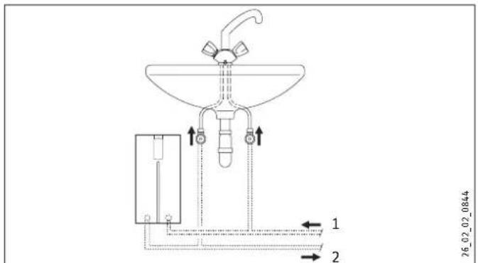
text_image
26_02_02_0844 1 2Oversink installation
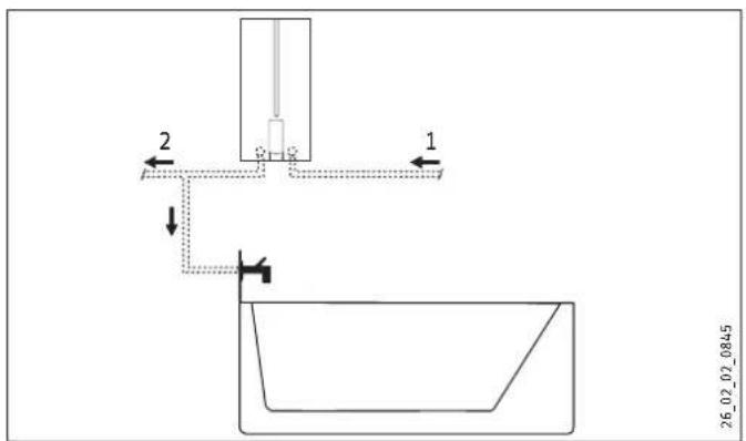
text_image
2 1 26_02_02_0845Mount the appliance on the wall. The wall must have
a sufficient load-bearing capacity.
9.2 Water installation
- No safety valve is required.
▶ Flush the water line thoroughly.
Taps/valves
Use suitable pressure taps/valves (see chapter "Installation / Appliance description / Accessories"). Open vented taps are not permitted.

Note
Never use the 3-way ball shut-off valve in the cold water inlet to reduce the flow rate. The 3-way ball shut-off valve is intended to shut off the appliance.
Permissible water line materials
- Cold water inlet line:
Pipes made from galvanised steel, stainless steel, copper or plastic
- DHW outlet line:
Pipes made from stainless steel, copper or plastic

Material losses
If plastic pipework is used, take into account the maximum inlet temperature and the maximum permissible pressure (see chapter "Installation / Specification / Data table").
Flow rate
▶ Ensure that the flow rate for switching on the appliance is achieved (see chapter "Installation / Specification / Data table", On).
▶ Increase the water line pressure if the required flow rate is not achieved when the draw-off valve is fully open. If the flow rate is not reached despite increasing the pressure, remove the flow limiter and install the plastic profile washer.
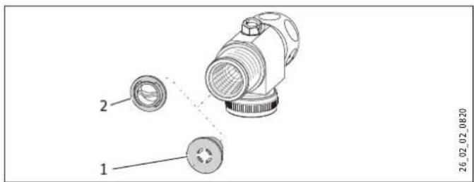
2 Plastic profile washer

Note
For the thermostatic valve to function correctly, the flow limiter must not be replaced with the plastic profile washer.
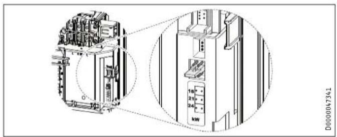
9.3 Appliance with adjustable connected load
The appliance DHB-E 18/21/24 SL is set to 21 kW when delivered. If the appliance is to be installed with a different output, take the following steps:
▶ Plug in the coding card according to the selected output; for selectable output and fuse protection of the appliance, see chapter "Installation / Specification / Data table".
Tick the selected output on the type plate. Use a permanent marker for this.
▶ Install the flow limiter with an output corresponding to that of the appliance (see chapter "Installation / Specification / Data table").
text_image
Technical diagram of an electrical enclosure with labeled components and a magnified view showing internal structure and power connections.10. Installation
Standard installation
- Electrical connection from below on unfinished walls
- Water connection on unfinished walls
For further installation options, see chapter "Installation / Installation options":
- Electrical connection from above on unfinished walls
- Electrical connection on finished walls
- Large conductor cross-section for electrical connection from below
- Connecting a load shedding relay
- Water installation on finished walls
- Water installation on finished walls with solder / compression fitting
- Water installation on finished walls; fitting the appliance cover
- Fitting the base part of the back panel with threaded fittings on finished walls
- Wall mounting bracket when replacing an appliance
- Installation with offset tiles
- Pivoting appliance cover
- Temperature limit / Anti-scalding protection
10.1 Standard installation
Opening the appliance
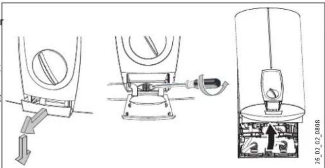
text_image
Technical diagram showing mechanical assembly steps with labeled components and directional arrows▶ Open the appliance by pulling the flap forwards and downwards, undo the screw and lift up the appliance cover.
natural_image
Technical diagram showing two mechanical assembly states with arrows indicating motion, no visible text or symbols▶ Remove the back panel by pressing the two locking hooks and pulling the base part of the back panel forwards.
Preparing the power cable
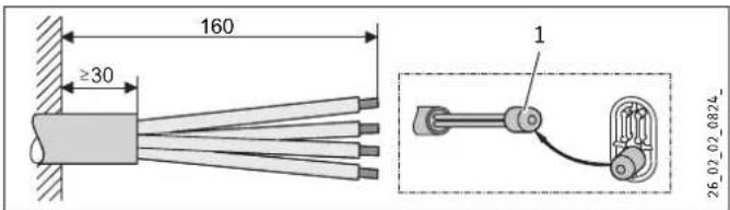
text_image
160 ≥30 1 26_02_02_0824_1 Installation aid
▶ Prepare the power cable.
Fitting the wall mounting bracket
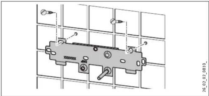
text_image
26_02_02_0810_▶ Mark out the holes for drilling using the installation template. If the appliance is to be installed with water connections on finished walls, also mark out a fixing hole in the lower part of the template.
Drill the holes and secure the wall mounting bracket at 2 points using suitable fixing materials (screws and rawl plugs are not part of the standard delivery).
▶ Fit the wall mounting bracket.
Making the water connection

Material losses
Carry out all water connection and installation work in accordance with regulations.
D0000053319
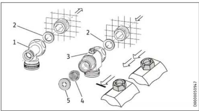
▶ Seal and insert the twin connectors.
text_image
1 2 3 4 5 D00000509471 DHW with tee
2 Gasket
3 Cold water with 3-way ball shut-off valve
4 Strainer
5 Flow limiter or plastic profile washer (see chapter "Installation / Water installation / Flow rate")

Note
A second flow limiter is provided with the DHB-E 18/21/24 SL. Install the appropriate flow limiter for output of the appliance (see "Flow rate regulator" in chapter "Installation / Specification / Data table"):
4.0 l/min = pink
7.5 l/min = blue
8.5 l/min = green
- Secure the tee and and 3-way ball shut-off valve, each with flat gasket, to the twin connector.

Material losses
Never use the 3-way ball shut-off valve in the cold water inlet to reduce the flow rate.
Installing the appliance
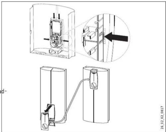
natural_image
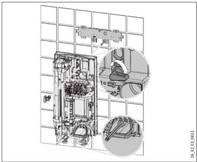
Technical line drawing of an industrial electrical cabinet with internal components and two circular insets showing close-ups (no text or symbols)▶ For easier installation, push the cable grommet of the upper electrical connection into the back panel from behind.
▶ Remove the transport plugs from the water connections.
Remove the fixing toggle from the upper part of the back panel.
▶ Route the power cable through the cable grommet from behind until the power cable rests against the cable sheath. Align the power cable.
Enlarge the hole in the cable grommet if the cross-section of the power cable is > 6 mm ^2 .
▶ Push the appliance over the threaded stud of the wall mounting bracket, so that it breaks through the soft seal. If necessary, use a screwdriver.
▶ Push the fixing toggle on to the threaded stud of the wall mounting bracket.
▶ Push the back panel firmly against the wall. Lock the fixing toggle by turning it 90° clockwise.
natural_image
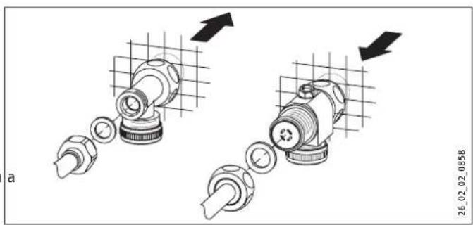
Mechanical assembly diagram showing two stages of a mechanical component with arrows indicating motion direction (no text or symbols)▶ Fit the pipes with flat gaskets onto the twin connectors.

Material losses
The strainer must be fitted for the appliance to function.
▶ When replacing an appliance, check whether the strainer is installed.
Making the electrical connection

WARNING Electrocution
Carry out all electrical connection and installation work in accordance with relevant regulations.

WARNING Electrocution
The connection to the power supply must be in the form of a permanent connection in conjunction with the removable cable grommet. Ensure the appliance can be separated from the power supply by an isolator that disconnects all poles with at least 3 mm contact separation.

WARNING Electrocution
Ensure that the appliance is earthed.

Material losses
Observe the type plate. The specified voltage must match the mains voltage.
▶ Connect the power cable to the mains terminal (see chapter "Installation / Specification / Wiring diagrams").
Fitting the base part of the back panel
natural_image
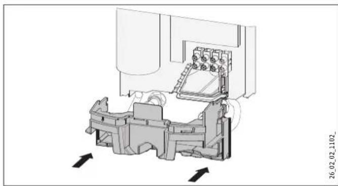
Technical diagram of a mechanical assembly with internal components and directional arrows (no text or symbols)▶ Fit the base part into the back panel. Click the base part into place.
▶ Align the mounted appliance by loosening the fixing toggle, aligning the power supply and back panel, and then re-tightening the fixing toggle. If the back panel does not sit flush against the wall, you can secure the appliance at the bottom with an additional screw.
10.2 Completing the installation
▶ Open the 3-way ball shut-off valve or the shut-off valve in the cold water supply line.
11. Commissioning

WARNING Electrocution
Commissioning may only be carried out by a qualified contractor in accordance with safety regulations.
11.1 Initial start-up
text_image
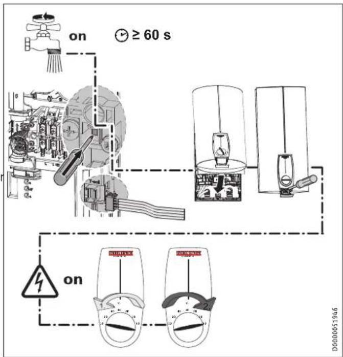
on ≥ 60 s on D0000051946▶ Open and close all connected draw-off valves several times, until all air has been purged from the pipework and the appliance.
▶ Carry out a tightness check.
▶ Activate the safety pressure limiter at flow pressure by firmly pressing in the reset button (the appliance is delivered with the safety pressure limiter deactivated).
▶ Plug the set value transducer cable plug into the PCB.
▶ Fit the appliance cover. Check that the appliance cover is seated correctly.
▶ Secure the appliance cover with the screw.
▶ Switch the mains power ON.
▶ Calibrate the temperature. Turn the temperature selector fully clockwise then fully anti-clockwise.
▶ Remove the protective foil from the control fascia.
▶ Check the function of the appliance.
Appliance handover
Explain the appliance function to users and familiarise them with its operation.
▶ Make the user aware of potential dangers, especially the risk of scalding.
▶ Hand over these instructions.
11.2 Recommissioning

Material losses
To ensure that the bare wire heating system is not damaged following an interruption to the water supply, the appliance must be restarted taking the following steps.
▶ Disconnect the appliance from the power supply by removing the fuses/tripping the MCBs.
▶ Open the tap for one minute until the appliance and its upstream cold water inlet line are free of air.
▶ Switch the mains power back ON again.
12. Shutdown
▶ Isolate all poles of the appliance from the power supply.
- Drain the appliance (see chapter "Installation / Maintenance / Draining the appliance").
13. Installation options
13.1 Electrical connection from above on unfinished walls
text_image
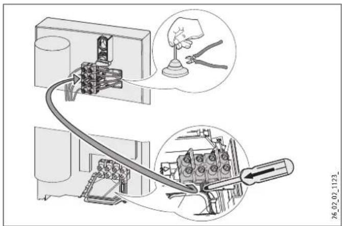
Technical diagram showing mechanical assembly with labeled parts and a magnified view of tool application▶ Cut open the cable grommet for the power cable.
▶ Push down the locking hook for securing the mains terminal. Pull out the mains terminal.
▶ Reposition the mains terminal in the appliance from the bottom to the top. Secure the mains terminal by sliding it under the locking hook.
Route the control wires under the wire guide.
13.2 Electrical connection on finished walls

Note
This type of connection changes the protection rating of the appliance.
▶ Change the type plate. Cross out "IP 25" and mark the box "IP 24". Please use a ballpoint pen to do this.

Material losses
If you break open the wrong knock-out in the back panel by mistake, you must use a new back panel.
▶ Cleanly cut or break out the required cable entry in the back panel (for positions, see chapter "Installation / Specification / Dimensions and connections"). Deburr sharp edges with a file if necessary.
Route the power cable through the cable grommet. Connect the power cable to the mains terminal.
13.3 Large conductor cross-section for electrical connection from below
If you use cables with a large cross-section, you can fit the cable grommet after the appliance has been installed.
text_image
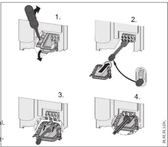
1. 2. 3. 4.▶ Before installing the appliance, use a screwdriver to push out the cable grommet.
▶ Slide the cable grommet over the power cable. Use the installation aid supplied in the standard delivery. If the cross-section is >6 mm², enlarge the hole in the cable grommet.
▶ Push the cable grommet into the back panel. Click the cable grommet into place.
13.4 Connecting a load shedding relay
When operating additional electric appliances, such as electric storage heaters, install a load shedding relay in the distribution board. The relay responds when the instantaneous water heater starts.

Material losses
Connect the phase that switches the load shedding relay to the indicated terminal of the mains terminal in the appliance (see chapter "Installation / Specification / Wiring diagrams").
13.5 Water installation on finished walls

Note
This type of connection changes the protection rating of the appliance.
▶ Change the type plate. Cross out "IP 25" and mark the box "IP 24". Please use a ballpoint pen to do this.
text_image
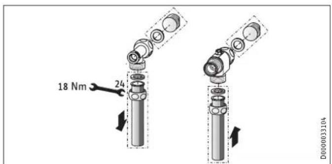
18 Nm 24 D000033104▶ Fit water plugs with gaskets to seal the in-wall connection. All taps listed under "Accessories" are supplied with plugs and gaskets as part of their standard delivery. For pressure taps other than those we recommend, plugs and gaskets can be ordered as "Accessories".
▶ Fit a suitable pressure tap.
▶ Push the base part of the back panel under the connecting pipes of the tap and push it into the back panel.
- Secure the connection pipes to the tee and the 3-way ball shut-off valve.
13.6 Water installation on finished walls with solder / compression fitting
You can connect copper or plastic pipes using the accessories "solder fitting" or "compression fitting".
With "solder fitting" with threaded connection for 12 mm copper pipes, proceed as follows:
▶ Push the union nuts over the connection pipes.
▶ Solder the inserts to the copper pipes.
▶ Push the base part of the back panel under the connecting pipes of the tap and push it into the back panel.
- Secure the connection pipes to the tee and the 3-way ball shut-off valve.

Note
Observe the tap manufacturer's instructions.
13.7 Water installation on finished walls; fitting the appliance cover
text_image
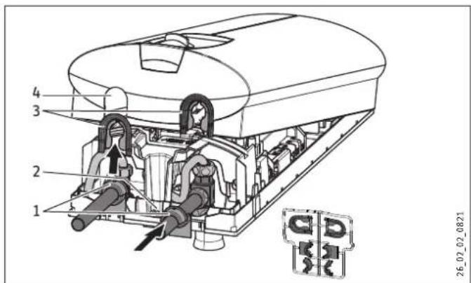
1 2 3 4 26_02_02_08211 Back panel guide pieces
2 Screw
3 Cover guide pieces
4 Pipe aperture
▶ Cleanly break out the knock-out apertures in the appliance cover. If necessary, use a file.

Note
Use the cap guide pieces if the connection pipes are slightly offset.
▶ If the connection pipes are substantially offset, do not fit the back panel guide pieces.
▶ When installing connection pipes without offset, break off the tabs on the cover guide pieces.
▶ Click the cover guides into place in the knock-out apertures.
▶ Position the back panel guide pieces on the pipes. Push them together. Then push the guide pieces against the back panel as far possible.
▶ Secure the back panel at the bottom with a screw.
▶ If you use flexible water connection pipes, prevent pipe bends from twisting (bayonet connections in the appliance).
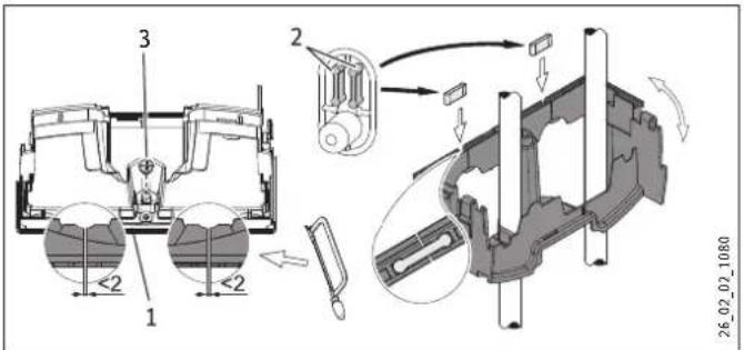
13.8 Fitting the base part of the back panel with threaded fittings on finished walls
If using threaded connections for finished walls, the base part of the back panel can also be installed after fitting the taps. To do this, carry out the following steps:
▶ Saw open the base part of the back panel.
▶ Fit the base part of the back panel by bending it out at the sides and guiding it over the pipes.
▶ Insert the connection pieces into the base part of the back panel from behind.
▶ Click the base part into place in the back panel.
▶ Secure the base part of the back panel with a screw.
text_image
3 2 1 <2 <2 26_02_02_10801 Base part of the back panel
2 Connection pieces delivered in the pack
3 Screw
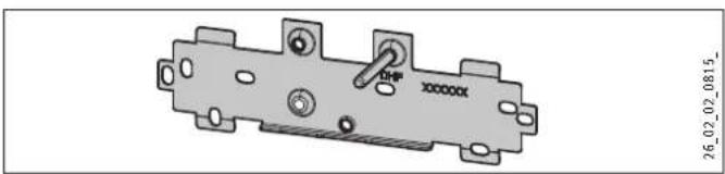
13.9 Wall mounting bracket when replacing an appliance
An existing STIEBEL ELTRON wall mounting bracket may be used when replacing appliances (except for DHF instantaneous water heater).
▶ Break through the back panel of the appliance for the threaded stud on the installed wall mounting bracket.
Replacing a DHF instantaneous water heater
natural_image
Mechanical component diagram with mounting holes and a central knob (no text or symbols)▶ Reposition the threaded stud on the wall mounting bracket (the stud has a self-tapping thread).
▶ Rotate the wall mounting bracket 180^ and mount it on the wall (the DHF logo is then turned towards the reader).
13.10 Installation with offset tiles
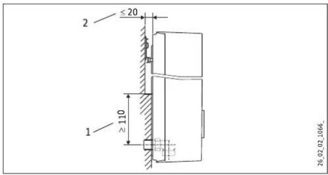
text_image
2 ≤ 20 ≥ 110 1 26_02_02_1066_1 Minimum contact area of the appliance
2 Maximum tile offset
▶ Adjust the wall clearance. Lock the back panel in place using the fixing toggle (turn 90° clockwise).
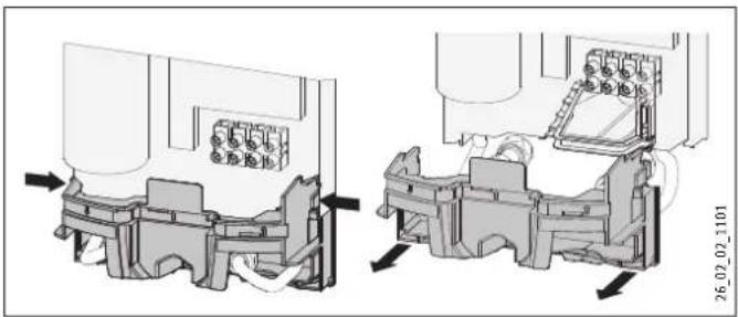
13.11 Pivoting appliance cover
The appliance cover can be turned round for undersink installation.
text_image
Technical diagram showing mechanical assembly with labeled components and a magnified detail view▶ Remove the programming unit from the appliance cover by pressing the locking hooks.
▶ Turn the appliance cover and click the programming unit back into place, ensuring that all locking hooks are engaged. For easier installation of the programming unit, press against the inner side of the appliance cover in the shaded area.
Material losses
Do not install a programming unit with faulty locking hooks. Otherwise the safety of the appliance cannot be guaranteed.
▶ Plug the set value transducer cable into the PCB (see chapter "Installation / Commissioning / Initial start-up").
▶ Hook the appliance cover in at the top. Pivot the appliance cover down onto the back panel and press down until it engages audibly.
▶ Secure the appliance cover.
13.12 Temperature limit / Anti-scalding protection
The maximum temperature can be limited to 43 °C on the programming unit of the appliance cover. For this, the following steps are necessary:
▶ Remove the appliance cover.
▶ Remove the electronic PCB from the programming unit of the appliance cover. Be careful with the snap-on hooks.
▶ Move the plug from left to right (position "43 °C").
▶ Refit the programming unit, ensuring the snap-on hooks click into place. Observe the positions of the push-button and shaft.

CAUTION Burns
If operating the appliance with preheated water, the set temperature limit and anti-scalding protection may be ineffective.
In this case, restrict the temperature at the upstream central thermostatic valve (see chapter "Installation / Appliance description / Accessories").
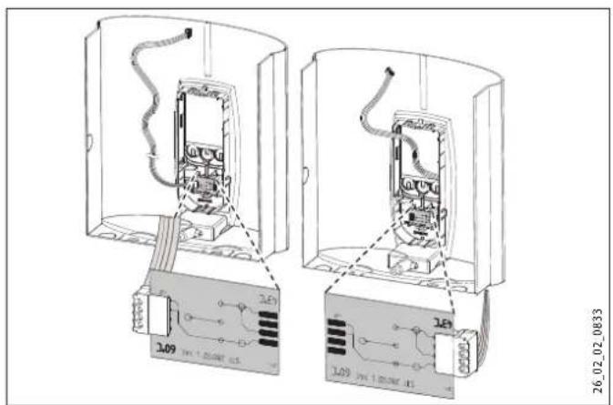
text_image
Technical diagram showing two views of an electronic device with labeled components and wiring connections14. Troubleshooting

WARNING Electrocution
To test the appliance, it must be supplied with power.
Indication variants for diagnostic traffic light (LED)
| Red Illuminates in the event of a fault | |
| Yellow Illuminates during heating operation | |
| Green Flashing: Appliance is supplied with mains power |
| Fault / LED diagnostic traffic light signal Cause Remedy | |||
| The appliance does not start. | The shower head / aerators are scaled up. | Descale or if necessary replace the shower head / aerators. | |
| The flow rate is too low. | The strainer in the appliance is dirty. | Clean the strainer. | |
| The set temperature is not achieved. | One phase down. | Check the fuse/MCB in your fuse box/distribution panel. | |
| The heater switches off. | The air detector senses air in the water. Heating output cuts out temporarily. | The appliance restarts after one minute. | |
| No hot water and no traffic light display. | The MCB/fuse has responded/blown. | Check the fuse/MCB in your fuse box/distribution panel. | |
| The safety pressure limiter has tripped. | Remove the cause of the fault (e.g. faulty pressure flush). | ||
| Protect the heating system against overheating by opening a draw-off valve downstream from the appliance for one minute. This depressurises and cools down the heating system. | |||
| Activate the safety pressure limiter at flow pressure by pressing the reset button, also see chapter "Installation / Commissioning / Initial start-up". | |||
| The PCB is faulty. | Check the PCB and replace if necessary. | ||
| Traffic light display: Green flashing No hot water at flow rate >3 l/min. | Flow sensor DFE is not plugged in. | Re-insert the flow sensor plug. | |
| Flow sensor DFE is faulty. | Check the flow sensor and replace if necessary. | ||
| The set temperature is not achieved. | The set value transducer or connecting cable is faulty, or the connecting cable is not attached. | Attach the connecting cable; replace the set value transducer if required. | |
| Temperature limiting is enabled. | Disable temperature limiting. | ||
| Traffic light display: Yellow constantly on; green flashing No hot water at flow rate >3 l/min. | The high limit safety cut-out has responded or suffered a lead break. | Check the high limit safety cut-out and replace if necessary. | |
| The heating system is faulty. | Check the resistance of the heater and replace if necessary. | ||
| The PCB is faulty. | Check the PCB and replace if necessary. | ||
| Traffic light display: Yellow constantly on; green flashing | The outlet sensor is faulty. | Check the connection and replace the outlet sensor if necessary. | |
| Set temperature is not achieved. | Appliance is operating at its output limit. | Reduce the flow rate. Install the flow limiter. | |
| Traffic light display: Red constantly on; green flashing | The outlet sensor is faulty. | Check the connection and replace the outlet sensor if necessary. | |
| No hot water | The cold water sensor is faulty. | Check the PCB and replace if necessary. | |
| Required temperature >45 °C not reached. | The cold water inlet temperature exceeds 45 °C. | Reduce the cold water inlet temperature to the appliance. | |
15. Maintenance

WARNING Electrocution
Before any work on the appliance, ensure omnipolar disconnection from the power supply.
Draining the appliance
The appliance can be drained for maintenance work.

WARNING Burns
Hot water may escape when you drain the appliance.
▶ Close the 3-way shut-off valve or the shut-off valve in the cold water supply line.
▶ Open all draw-off valves.
▶ Undo the water connections on the appliance.
▶ If dismantled, store the appliance in a room free from the risk of frost, as water residues remaining inside the appliance can freeze and cause damage.
Cleaning the strainer
If contaminated, clean the strainer in the threaded cold water fitting. Close the 3-way shut-off valve or the shut-off valve in the cold water supply line before removing, cleaning and refitting the strainer.
16. Specification
16.1 Dimensions and connections
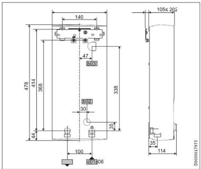
text_image
140 478 414 368 44 100 b03 b02 30 b c01d06 338 105≤202 35 114 D0000017973| DHB-E SLi | |||
| b02 | Entry for cables I | ||
| b03 | Entry for cables II | ||
| c01 | Cold water inlet | Male thread | G 1/2 A |
| c06 | DHW outlet | Male thread | G 1/2 A |
Alternative connection options
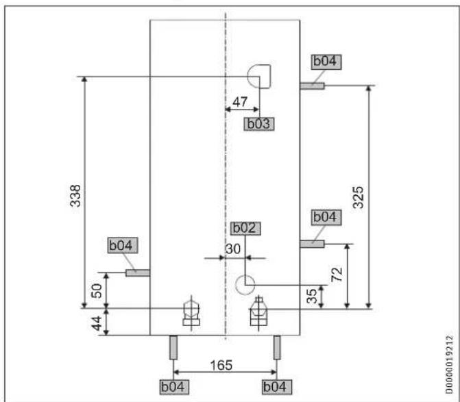
text_image
338 b04 50 44 165 b04 b02 30 47 b03 b04 325 72 35 b04 b04 D0000019212| DHB-E SLi | |
| b02 Entry for cables I | |
| b03 Entry for cables II | |
| b04 Entry for cables III |
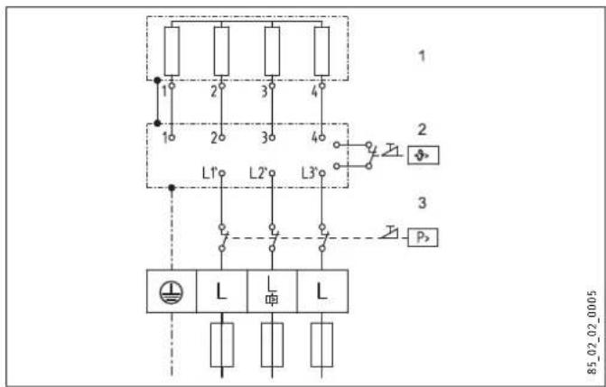
16.2 Wiring diagram
3/PE \~ 380-415 V
text_image
1 2 3 4 L1° L2° L3° L L L 85_02_02_00051 Heater
2 High limit safety cut-out
3 Safety pressure limiter
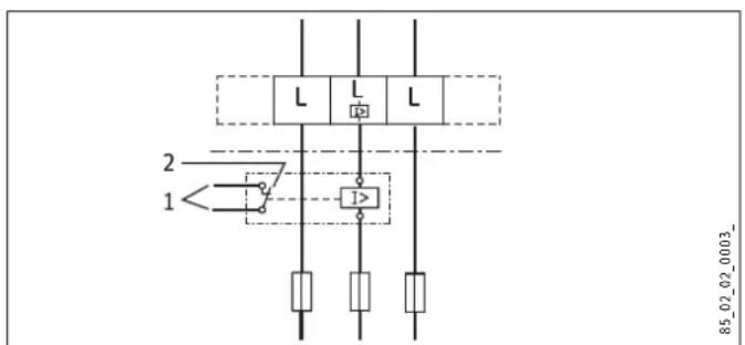
Priority control with LR 1-A
text_image
L L L 2 1 I> 85_02_02_0003_1 Control cable to the contactor of the second appliance (e.g. electric storage heater).
2 Control contact opens when switching the instantaneous water heater on.
16.3 DHW output
The DHW output is subject to the mains voltage, the appliance's connected load and the cold water inlet temperature. The rated voltage and rated output can be found on the type plate (see chapter "Operation / Troubleshooting").
Connected load in kW 38 °C DHW output in L/min.
| Rated voltage Cold water inlet temperature | ||||||
| 380 V | 400 V | 415 V | 5 °C | 10 °C | 15 °C | 20 °C |
| 10.1 | 4.4 | 5.2 | 6.3 | 8.0 | ||
| 11.0 | 4.8 | 5.6 | 6.8 | 8.7 | ||
| 12.0 | 5.2 | 6.1 | 7.5 | 9.5 | ||
| 12.2 | 5.3 | 6.2 | 7.6 | 9.7 | ||
| 13.2 | 5.7 | 6.7 | 8.2 | 10.5 | ||
| 13.5 | 5.8 | 6.9 | 8.4 | 10.7 | ||
| 13.6 | 5.9 | 6.9 | 8.4 | 10.8 | ||
| 14.2 | 6.1 | 7.2 | 8.8 | 11.3 | ||
| 14.5 | 6.3 | 7.4 | 9.0 | 11.5 | ||
| 15.0 | 6.5 | 7.7 | 9.3 | 11.9 | ||
| 16.2 | 7.0 | 8.3 | 10.1 | 12.9 | ||
| 16.3 | 7.1 | 8.3 | 10.1 | 12.9 | ||
| 18.0 | 7.8 | 9.2 | 11.2 | 14.3 | ||
| 19.0 | 8.2 | 9.7 | 11.8 | 15.1 | ||
| 19.4 | 8.4 | 9.9 | 12.0 | 15.4 | ||
| 21.0 | 9.1 | 10.7 | 13.0 | 16.7 | ||
| 21.7 | 9.4 | 11.1 | 13.5 | 17.2 | ||
| 22.6 | 9.8 | 11.5 | 14.0 | 17.9 | ||
| 23.5 | 10.2 | 12.0 | 14.6 | 18.7 | ||
| 24.0 | 10.4 | 12.2 | 14.9 | 19.0 | ||
| 24.4 | 10.6 | 12.4 | 15.2 | 19.4 | ||
| 25.8 | 11.2 | 13.2 | 16.0 | 20.5 | ||
| 26.0 | 11.3 | 13.3 | 16.1 | 20.6 | ||
| 27.0 | 11.7 | 13.8 | 16.8 | 21.4 | ||
Connected load in kW 50 °C DHW output in L/min.
| Rated voltage Cold water inlet temperature | ||||||
| 380 V | 400 V | 415 V | 5 °C | 10 °C | 15 °C | 20 °C |
| 10.1 | 3.2 | 3.6 | 4.1 | 4.8 | ||
| 11.0 | 3.5 | 3.9 | 4.5 | 5.2 | ||
| 12.0 | 3.8 | 4.3 | 4.9 | 5.7 | ||
| 12.2 | 3.9 | 4.4 | 5.0 | 5.8 | ||
| 13.2 | 4.2 | 4.7 | 5.4 | 6.3 | ||
| 13.5 | 4.3 | 4.8 | 5.5 | 6.4 | ||
| 13.6 | 4.3 | 4.9 | 5.6 | 6.5 | ||
| 14.2 | 4.5 | 5.1 | 5.8 | 6.8 | ||
| 14.5 | 4.6 | 5.2 | 5.9 | 6.9 | ||
| 15.0 | 4.8 | 5.4 | 6.1 | 7.1 | ||
| 16.2 | 5.1 | 5.8 | 6.6 | 7.7 | ||
| 16.3 | 5.2 | 5.8 | 6.7 | 7.8 | ||
| 18.0 | 5.7 | 6.4 | 7.3 | 8.6 | ||
| 19.0 | 6.0 | 6.8 | 7.8 | 9.0 | ||
| 19.4 | 6.2 | 6.9 | 7.9 | 9.2 | ||
| 21.0 | 6.7 | 7.5 | 8.6 | 10.0 | ||
| 21.7 | 6.9 | 7.8 | 8.9 | 10.3 | ||
| 22.6 | 7.2 | 8.1 | 9.2 | 10.8 | ||
| 23.5 | 7.5 | 8.4 | 9.6 | 11.2 | ||
| 24.0 | 7.6 | 8.6 | 9.8 | 11.4 | ||
| 24.4 | 7.7 | 8.7 | 10.0 | 11.6 | ||
| 25.8 | 8.2 | 9.2 | 10.5 | 12.3 | ||
| 26.0 | 8.3 | 9.3 | 10.6 | 12.4 | ||
| 27.0 | 8.6 | 9.6 | 11.0 | 12.9 | ||
16.4 Application areas / conversion table
Specific electrical resistance and specific electrical conductivity (see chapter "Installation / Data table").
| Standard specification at 15 °C | 20 °C | 25 °C | ||||||
| Resistance ρ ≥ | Conductivity σ ≤ | Resistance ρ ≥ | Conductivity σ ≤ | Resistance ρ ≥ | Conductivity σ ≤ | |||
| Ωcm | mS/m | μS/cm | Ωcm | mS/m | μS/cm | Ωcm | mS/m | μS/cm |
| 900 | 111 | 1111 | 800 | 125 | 1250 | 735 | 136 | 1361 |
| 1000 | 100 | 1000 | 890 | 112 | 1124 | 815 | 123 | 1227 |
| 1100 | 91 | 909 | 970 | 103 | 1031 | 895 | 112 | 1117 |
| 1200 | 83 | 833 | 1070 | 93 | 935 | 985 | 102 | 1015 |
| 1300 | 77 | 769 | 1175 | 85 | 851 | 1072 | 93 | 933 |
16.5 Pressure drop
Taps/valves
| Tap pressure drop at a flow rate of 10 U/min | ||
| Mono lever mixer tap, approx. | MPa | 0.04 - 0.08 |
| Thermostatic valve, approx. | MPa | 0.03 - 0.05 |
| Shower head, approx. | MPa | 0.03 - 0.15 |
Sizing the pipework
When calculating the size of the pipework, an appliance pressure drop of 0.1 MPa is recommended.
16.6 Fault conditions
In the event of a fault, loads up to a maximum of 95 ^ at a pressure of 1.2 MPa can occur temporarily in the installation.
16.7 Country-specific approvals and certifications: Germany
In line with [German] State Building Regulations, a general test certificate has been issued for the appliance, as verification of its suitability regarding noise emissions.
text_image
STIEBEL ELTRON DIN 4109 PA-IX 6816/I LGA16.8 Details on energy consumption
The product data complies with EU regulations relating to the Directive on the ecological design of energy related products (ErP).
| DHB-E 11 SLi DHB-E 13 SLi DHB-E 18 SLi 25 A DHB-E 18/21/24 SLi DHB-E 27 SLi | ||||||
| 232013 | 232014 | 232015 | 232016 | 232017 | ||
| Manufacturer | STIEBEL ELTRON | STIEBEL ELTRON | STIEBEL ELTRON | STIEBEL ELTRON | STIEBEL ELTRON | |
| Load profile | S | S | S | S | S | |
| Energy efficiency class | A | A | A | A | A | |
| Annual power consumption | kWh | 472 | 472 | 477 | 477 | 481 |
| Energy conversion efficiency | % | 39 | 39 | 39 | 39 | 39 |
| Default temperature setting | °C | 60 | 60 | 60 | 60 | 60 |
| Sound power level | dB(A) | 15 | 15 | 15 | 15 | 15 |
| Special information on measuring efficiency | None | None | None | Data at Pmax. | None | |
16.9 Data table
| DHB-E 11 SLi DHB-E 13 SLi DHB-E 18 SLi 25 A DHB-E 18/21/24 SLi DHB-E 27 SLi | |||||||||||||||
| 232013 | 232014 | 232015 | 232016 | 232017 | |||||||||||
| Electrical data | |||||||||||||||
| Rated voltage | V | 380 | 400 | 415 | 380 | 400 | 415 | 380 | 400 | 415 | 380 | 400 | 415 | 380 | 400 |
| Rated output | kW | 10.1 | 11 | 12.2 | 13.5 | 14.5 | 16.2 | 18 | 19.4 | 16.2/19/21.7 | 18/21/24 | 19.4/22.6/25.8 | 24.4 | 27 | |
| Rated current | A | 15.4 | 16 | 18.5 | 19.5 | 20.2 | 24.7 | 26 | 27 | 27.6/29.5/33.3 | 29/31/35 | 30.1/32.2/36.3 | 37.1 | 39 | |
| MCB/fuse rating | A | 16 | 16 | 20 | 20 | 20 | 25 | 25 | 32 | 32/32/35 | 32/32/35 | 32/32/40 | 40 | 40 | |
| Phases | 3/PE | 3/PE | 3/PE | 3/PE | 3/PE | ||||||||||
| Frequency | Hz | 50/60 | 50/60 | 50/60 | 50/60 | 50/- | 50/60 | 50/60 | 50/- | 50/60 | 50/60 | 50/- | 50/- | 50/- | |
| Specific resistance _15 ≥ (at cold ≤ 25^) | Ω cm | 900 | 900 | 1000 | 900 | 900 | 1000 | 900 | 900 | 1000 | 900 | 900 | 1000 | 900 | 900 |
| Specific conductivity _15 ≤ (at cold ≤ 25^) | μS/cm | 1111 | 1111 | 1000 | 1111 | 1111 | 1000 | 1111 | 1111 | 1000 | 1111 | 1111 | 1000 | 1111 | 1111 |
| Specific resistance _15 ≥ (at cold ≤ 45^) | Ω cm | 1200 | 1200 | 1300 | 1200 | 1200 | 1300 | 1200 | 1200 | 1300 | 1200 | 1200 | 1300 | 1200 | 1200 |
| Specific conductivity _15 ≤ (at cold ≤ 45^) | μS/cm | 833 | 833 | 770 | 833 | 833 | 770 | 833 | 833 | 770 | 833 | 833 | 770 | 833 | 833 |
| Max. mains impedance at 50 Hz | Ω | 0.379 | 0.360 | 0.347 | 0.284 | 0.270 | 0.260 | 0.254 | 0.241 | ||||||
| Connections | |||||||||||||||
| Water connection | G 1/2 A | G 1/2 A | G 1/2 A | G 1/2 A | G 1/2 A | ||||||||||
| Application limits | |||||||||||||||
| Max. permissible pressure | MPa | 1 | 1 | 1 | 1 | 1 | |||||||||
| Max. inlet temperature for reheating | °C | 45 | 45 | 45 | 45 | 45 | |||||||||
| Values | |||||||||||||||
| Max. permissible inlet temperature | °C | 60 | 60 | 60 | 60 | 60 | |||||||||
| On | l/min | >3.0 | >3.0 | >3.0 | >3.0 | >3.0 | |||||||||
| Flow rate for pressure drop | l/min | 3.1 | 3.9 | 5.2 | 5.2/6.0/6.9 | 7.7 | |||||||||
| Pressure drop at flow rate | MPa | 0.07 (0.02 without DMB) | 0.11 (0.03 without DMB) | 0.08 (0.06 without DMB) | 0.08/0.10/0.13 (0.06/0.08/0.10 without DMB) | 0.16 (0.12 without DMB) | |||||||||
| Flow rate limit at | l/min | 4.0 | 4.0 | 7.5 | 7.5/7.5/8.5 | 8.5 | |||||||||
| DHW delivery | l/min | 5.6 | 6.9 | 9.2 | 9.2/10.7/12.3 | 13.8 | |||||||||
| Δθ on delivery | K | 28 | 28 | 28 | 28 | 28 | |||||||||
| Hydraulic data | |||||||||||||||
| Nominal capacity | l | 0.4 | 0.4 | 0.4 | 0.4 | 0.4 | |||||||||
| Versions | |||||||||||||||
| Connected load adjustable | - | - | - | X | - | ||||||||||
| Temperature setting range | °C | 30 - 60 | 30 - 60 | 30 - 60 | 30 - 60 | 30 - 60 | |||||||||
| Safety category | 1 | 1 | 1 | 1 | 1 | ||||||||||
| Insulating block | Plastic | Plastic | Plastic | Plastic | Plastic | ||||||||||
| Heating system heat generator | Bare wire | Bare wire | Bare wire | Bare wire | Bare wire | ||||||||||
| Cover and back panel | Plastic | Plastic | Plastic | Plastic | Plastic | ||||||||||
| Colour | White | White | White | White | White | ||||||||||
| IP rating | IP 25 | IP 25 | IP 25 | IP 25 | IP 25 | ||||||||||
| Dimensions | |||||||||||||||
| Height | mm | 478 | 478 | 478 | 478 | 478 | |||||||||
| Width | mm | 225 | 225 | 225 | 225 | 225 | |||||||||
| Depth | mm | 105 | 105 | 105 | 105 | 105 | |||||||||
| Weights | |||||||||||||||
| Weight | kg | 3.6 | 3.6 | 3.6 | 3.6 | 3.6 | |||||||||
Guarantee
The guarantee conditions of our German companies do not apply to appliances acquired outside of Germany. In countries where our subsidiaries sell our products a guarantee can only be issued by those subsidiaries. Such guarantee is only granted if the subsidiary has issued its own terms of guarantee. No other guarantee will be granted.
We shall not provide any guarantee for appliances acquired in countries where we have no subsidiary to sell our products. This will not affect warranties issued by any importers.
Environment and recycling
We would ask you to help protect the environment. After use, dispose of the various materials in accordance with national regulations.
REMARQUES PARTICULIÈRES
UTILISATION
text_image
Technical diagram of a bathroom sink with labeled components and directional arrows indicating flow or movement.text_image
2 1 26_02_02_0845text_image
2 1 26_02_02_0820text_image
Technical diagram of an electrical control unit with labeled components and a magnified view showing internal wiring layout.10. Pose
Pose standard
text_image
Technical diagram showing mechanical assembly steps with labeled components and directional arrowsnatural_image
Technical diagram showing two mechanical assembly views with arrows indicating motion direction (no text or symbols)▶ Fixez le support mural.
natural_image
Technical illustration of an internal mechanical assembly with two circular insets showing close-ups of a device (no text or symbols present)26_02_02_0811
natural_image
Mechanical assembly diagram showing two connected components with directional arrows indicating motion (no text or symbols)natural_image
Technical diagram of a mechanical assembly with internal components and directional arrows (no text or symbols)text_image
on ≥ 60 s on D0000051946text_image
Technical diagram showing cable installation process with magnified views of components and tool usenatural_image
Mechanical component diagram with mounting holes and a central lever (no text or symbols)text_image
Technical diagram showing mechanical assembly with labeled components and a magnified detail viewtext_image
Technical diagram showing two views of an electrical enclosure with labeled components and wiring connectionstext_image
1 2 3 4 1 2 3 4 L1° L2° L3° L L L P 3 85_02_02_0005text_image
2 1 L L L 1> 85_02_02_0003_text_image
26_02_02_0844 1 21 Koudwatertoevoer
2 Warmwateruitloop
text_image
2 1 26_02_02_08451 Koudwatertoevoer
2 Warmwateruitloop

Info
text_image
Technical diagram showing mechanical assembly steps with labeled components and directional arrowsnatural_image
Mechanical assembly diagram showing two views of a device with internal components and directional arrows (no text or symbols)text_image
160 ≥30 1 26_02_02_0824_1 Montagehulp
text_image
XXXXXX 26_02_02_0810_natural_image
Technical line drawing of an industrial machine interior with internal components and two circular insets showing close-ups of mechanical parts (no text or symbols)26_02_02_0811
natural_image
Mechanical assembly diagram showing two connected components with arrows indicating motion direction (no text or symbols)natural_image
Technical diagram of a mechanical assembly with internal components and directional arrows (no text or symbols)text_image
Technical diagram showing mechanical assembly with labeled components and tool application notestext_image
1 2 3 4 26_02_02_0821natural_image
Mechanical component diagram with mounting holes and a central knob (no text or symbols)text_image
Technical diagram showing a mechanical assembly with labeled components and an inset detail view highlighting a specific part.text_image
Technical diagram showing two views of an electrical device with labeled components and wiring connections14. Storingen verhelpen

WAARSCHUWING verbranding
text_image
1 2 3 4 L1° L2° L3° L L L 85_02_02_0005text_image
2 1 L L L 1> 85_02_02_0003_text_image
Technical diagram of a bathroom sink with labeled components and directional arrows indicating flow or movement.text_image
2 1 26_02_02_0845text_image
2 1 26_02_02_0820text_image
Technical diagram of an electrical control unit with labeled components and a magnified view showing internal structure and power connections.10. Montaż
Montaż standardowy
text_image
zy 26_02_02_0808natural_image
Technical diagram of a mechanical assembly with two views showing internal components and directional arrows (no text or symbols)text_image
160 ≥30 1 26_02_02_0824_1 Pomoc montażowa
natural_image
Technical diagram of an electrical enclosure with internal components and two circular insets showing close-ups of mechanical parts (no text or labels)natural_image
Mechanical assembly diagram showing two connected components with directional arrows indicating motion (no text or symbols)natural_image
Technical diagram of a mechanical assembly with internal components and directional arrows (no text or symbols)text_image
on ≥ 60 s on D0000051346text_image
Technical diagram showing mechanical assembly with labeled components and close-up views of tool pathtext_image
1 2 3 4 26_02_02_0821text_image
Technical diagram showing mechanical assembly with labeled components and directional arrows indicating motion or movement.natural_image
Mechanical component diagram with mounting holes and a central shaft (no text or symbols)natural_image
Technical diagram of a mechanical assembly inside a housing, showing internal components and an inset view with an arrow indicating direction (no text or labels present)
natural_image
Diagram of two cylindrical containers connected by a cable, showing internal components (no text or symbols)26_02_02_0817
text_image
Technical diagram showing two views of an electrical enclosure with labeled components and wiring connectionstext_image
1 2 3 4 L1° L2° L3° L L L P 85_02_02_00051 Grzałki
text_image
2 1 L L L 1> 85_02_02_0003_text_image
Technical diagram of a bathroom sink with labeled components and directional arrowstext_image
2 1 26_02_02_0845text_image
2 1 26_02_02_0820text_image
Technical diagram of an electrical enclosure with labeled components and a close-up view showing internal structure and wiring details.10. Montáž
Standardní montáž
text_image
Technical diagram showing mechanical assembly steps with labeled components and directional arrowsnatural_image
Mechanical assembly diagram showing two views of a device with internal components and directional arrows (no text or symbols)text_image
26_02_02_0810_text_image
Technical diagram showing exploded view of a mechanical assembly with numbered components and directional arrows indicating assembly steps.natural_image
Technical line drawing of an electrical enclosure with internal components and two circular insets showing close-ups of mechanical parts (no text or symbols)natural_image
Mechanical assembly diagram showing two connected components with directional arrows indicating motion (no text or symbols)natural_image
Technical diagram of a mechanical assembly with internal components and directional arrows (no text or symbols)text_image
on ≥ 60 s on D0000051946text_image
Technical diagram showing cable installation process with magnified views of components and tool usetext_image
Technical diagram of a mechanical assembly with labeled components and motion indicatorsnatural_image
3D mechanical component diagram with mounting holes and a central knob (no text or symbols)natural_image
Technical diagram showing two views of a mechanical assembly with a close-up inset (no text or symbols)text_image
Technical diagram showing two views of an electrical device with labeled components and wiring connectionstext_image
1 2 3 4 L1° L2° L3° L L L 85_02_02_0005text_image
2 1 L L L 1> 85_02_02_0003_6 Prohasky Street | Port Melbourne VIC 3207
Tel. 03 9645-1833 | Fax 03 9645-4366
info@stiebel.com.au
www.stiebel.com.au
Austria
STIEBEL ELTRON Ges.m.b.H.
Eferdinger Str. 73 | 4600 Wels
Tel. 07242 47367-0 | Fax 07242 47367-42
info@stiebel-eltron.at
www.stiebel-eltron.at
Belgium
STIEBEL ELTRON bvba/sprl
't Hofveld 6 - D1 | 1702 Groot-Bijgaarden
Tel. 02 42322-22 | Fax 02 42322-12
info@stiebel-eltron.be
www.stiebel-eltron.be
China
STIEBEL ELTRON (Guangzhou) Electric
Appliance Co., Ltd.
Rm 102, F1, Yingbin-Yihao Mansion, No. 1
Yingbin Road
Panyu District | 511431 Guangzhou
Tel. 020 39162209 | Fax 020 39162203
info@stiebeleltron.cn
www.stiebeleltron.cn
Czech Republic
STIEBEL ELTRON spol. s r.o.
Urzhumskaya street 4,
building 2 | 129343 Moscow
Tel. 0495 7753889 | Fax 0495 7753887
info@stiebel-eltron.ru
www.stiebel-eltron.ru
Slovakia
TATRAMAT - ohrievače vody s.r.o.
Hlavná 1 | 058 01 Poprad
Tel. 052 7127-125 | Fax 052 7127-148
info@stiebel-eltron.sk
www.stiebel-eltron.sk
Switzerland
STIEBEL ELTRON AG
Industrie West
Gass 8 | 5242 Lupfig
Tel. 056 4640-500 | Fax 056 4640-501
info@stiebel-eltron.ch
www.stiebel-eltron.ch
Thailand
STIEBEL ELTRON Asia Ltd.
469 Moo 2 Tambol Klong-Jik
Amphur Bangpa-In | 13160 Ayutthaya
Tel. 035 220088 | Fax 035 221188
info@stiebeleltronasia.com
www.stiebeleltronasia.com
United Kingdom and Ireland
STIEBEL ELTRON UK Ltd.
Unit 12 Stadium Court
Stadium Road | CH62 3RP Bromborough
Tel. 0151 346-2300 | Fax 0151 334-2913
info@stiebel-eltron.co.uk
www.stiebel-eltron.co.uk
United States of America
STIEBEL ELTRON, Inc.
17 West Street | 01088 West Hatfield MA
Tel. 0413 247-3380 | Fax 0413 247-3369
info@stiebel-eltron-usa.com
www.stiebel-eltron-usa.com

text_image
4017212968512Irrtum und technische Änderungen vorbehalten! | Subject to errors and technical changes! | Sous réserve d'erreurs et de modifications techniques! | Onder voorbehoud van vergissingen en technische wijzigingen! | Salvo error o modificación técnica! | Excepto erro ou alteração técnica | Zastrzeżone zmiany techniczne i ewentualne błędy | Omyly a technické zmény jsou vyhrazeny! | A muszaki változtatások és tévedések jo gát fenntartjuk! | Отсутствие ошибok ne гарантируется. Возможны технические изменения. | Chyby a technické zmeny sü vyhradené! Stand 9046