MTX 203 - Multimeter METRIX - Free user manual and instructions
Find the device manual for free MTX 203 METRIX in PDF.
| Product type | TRMS digital multimeter |
| Brand | Metrix (Chauvin Arnoux) |
| Model | MTX 203 |
| Dimensions (L × W × H) | 170 × 80 × 50 mm |
| Weight (with batteries) | 320 g |
| Power supply | 2 × 1.5 V AA batteries (LR6) |
| Battery life | Approximately 500 hours in VLowZ/VAC without backlight |
| Display | Monochrome digital, 52 × 37 mm, 6000 counts |
| Measurement category | CAT III 600 V |
| Protection rating | IP54 |
| Double insulation | Yes (class 2) |
| Operating temperature range | -20 °C to 55 °C |
| Operating relative humidity | Up to 90% RH (non-condensing) |
| Measurement functions | AC/DC voltage, AC/DC current, resistance, continuity, diodes, capacitance, temperature (K-type thermocouple), NCV, VLowZ |
| AC/DC voltage measurement | Input impedance 10 MΩ (V) or 500 kΩ (VLowZ) |
| AC/DC current measurement | Up to 10 A (A terminal), up to 600 mA (mA/μA terminal) |
| Continuity test | Threshold < 50 Ω |
| Protection fuses | F1: 630 mA / 1000 V / 10 kA (6.3×32 mm), F2: 10 A / 1000 V / 30 kA (10×38 mm) |
| Supplied accessories | 2 test leads (red/black), K-type adapter + sensor, set of batteries |
| Maintenance | Clean with a damp cloth and mild detergent; replace batteries when battery symbol appears on display |
| Warranty | 24 months from date of purchase |
| Repairability | Repairs by Chauvin Arnoux authorized personnel; spare parts available (fuses, batteries) |
| Metrological control | Recommended once per year |
Frequently Asked Questions - MTX 203 METRIX
User questions about MTX 203 METRIX
0 question about this device. Answer the ones you know or ask your own.
Ask a new question about this device
Download the instructions for your Multimeter in PDF format for free! Find your manual MTX 203 - METRIX and take your electronic device back in hand. On this page are published all the documents necessary for the use of your device. MTX 203 by METRIX.
USER MANUAL MTX 203 METRIX
- INSTRUCTIONS GÉNÉRALES....1
text_image
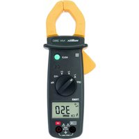
mmbix ACTM/CM D AIR Tmbx 203 1 4 8 7 6 5 14 15 V T O A Vcc NCV OFF 10A B2V GE R PREF MA RAN RAN RAN RAN RAN RAN RAN RAN RAN RAN RAN RAN RAN RAN RAN RAN RAN RAN RAN RAN RAN RAN RAN RAN RAN RAN RAN RAN RAN RAN RAN RAN RAN RANnatural_image
Technical line drawing of a cylindrical mechanical component with flanges and a side view (no text or symbols)
natural_image
Line drawing of a handheld electronic device with control panel and stand (no text or symbols)natural_image
Technical line drawing of a mobile phone casing with internal components and mounting holes (no text or symbols)text_image
Diagram of a multimeter with labeled terminals and connected to a power supply circuitMTX 203 VLowZ
text_image
Diagram of a multimeter with labeled terminals and connected to a voltmeter and ammeter connectiontext_image
Diagram of a multimeter with labeled components including voltage source, switch, and measurement dialMTX 203

text_image
Diagram of a multimeter with labeled terminals and connected to a power supply via a resistor and voltmeter.text_image
Diagram of a multimeter with labeled components including a digital display, analog dial, and electrical connectionstext_image
Diagram of a multimeter with labeled control panel and connected probe, showing measurement setuptext_image
Diagram of a multimeter with labeled controls and an AC input indicator showing voltage measurement.
text_image
Diagram of a digital multimeter with labeled control knobs and display screen1.1 Precautions and safety measures.... 12
1.1.1 Symbols.... 13
1.1.2 Measurement categories 13
- INSTRUMENT OVERVIEW....13
2.1 Introduction....13
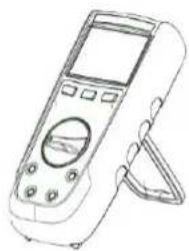
2.2 Device description....14
2.3 Display....16
2.4 Fixation and stand.... 16
- USE 17
3.1 First use 17
3.2 Backlight and Torch light....17
3.3 Measuring AC or DC voltages....17
3.4 Measuring AC or DC current....18
3.5 Measuring continuity 18
3.6 Measuring resistance....18
3.7 Testing Diodes 19
3.8 Measuring Capacitance 19
3.9 Measuring Temperature....20
3.10 Non Contact Voltage Detection (NCV) 20
3.11 VlowZ 20
- MAINTENANCE....21
4.1 Cleaning....21
4.2 Testing the 10A Fuse....21
4.3 Replacing the batteries and fuses....21
4.4 Metrological check 21
4.5 Service and Parts....21
-
WARRANTY 22
-
TO ORDER 22
- GENERAL SPECIFICATIONS....22
- TECHNICAL SPECIFICATIONS (See Appendix) 22
1. GENERAL INSTRUCTIONS
You have purchased a digital multimeter MTX 202 or MTX 203. Thank you for your confidence.
To get the best service of this multimeter :
- Read carefully this user's manual
- Respect the precautions for use
| Range | Digital-B ASYC Multimeters | |
| Model | MTX 202 | MTX 203 |
| Display | Digital, monochrome (52 x 37 mm) | |
| Count | 4000 | 6000 |
| Power supply | Batteries : 2 x 1.5V, R6, AA format | |
1.1 Precautions and safety measures
Failure to comply with safety instructions can create a risk of electrical shock, fire, explosion and
destruction of the instrument of the installations. If the device is used other than as specified in this manual, the protection provided by the device may be impaired.
- The operator and/or the responsible authority must carefully read and clearly understand the various precautions to be taken in use.
- Before using the instrument, make sure it works properly when measuring a known voltage, and check continuity by short circuiting both test leads.
- Do not use the instrument in an explosive atmosphere or in the presence of inflammable gas or smoke.
- Do not use the instrument on networks with a rated voltage or category higher than those mentioned.
- Respect the maximum rated voltages and currents between terminals and in relation to the earth.
- Do not use the instrument if it seems damaged, incomplete or incorrectly closed
-
Before each use, check the condition of the cable insulation, the unit and the accessories. All elements on which the insulation is damaged (even partially) must be put out of service for repair or disposed at waste.
-
Use cables and accessories for voltage according to IEC 61010-031 and measurement categories at least equal to those of the instrument. If not, an accessory of a lower category reduces the category of the combined multimeter + accessory to that of the accessory.
- Respect the environmental conditions of use.
- Strictly comply with the fuse specifications. Disconnect all cables before opening the fuse access cover.
- Do not modify the instrument and do not replace components using equivalent parts. Repairs and adjustments must be carried out by qualified, approved personnel.
- Replace the battery as soon as the symbol appears on the display. Disconnect all cables before opening the battery access cover.
- Use personal protection equipment when conditions require it.
- Keep your hands and fingers away from the unused terminals of the device. When handling sensors or test probes, do not place fingers beyond physical finger guard.
4000- and 6000-count TRMS digital multimeters English
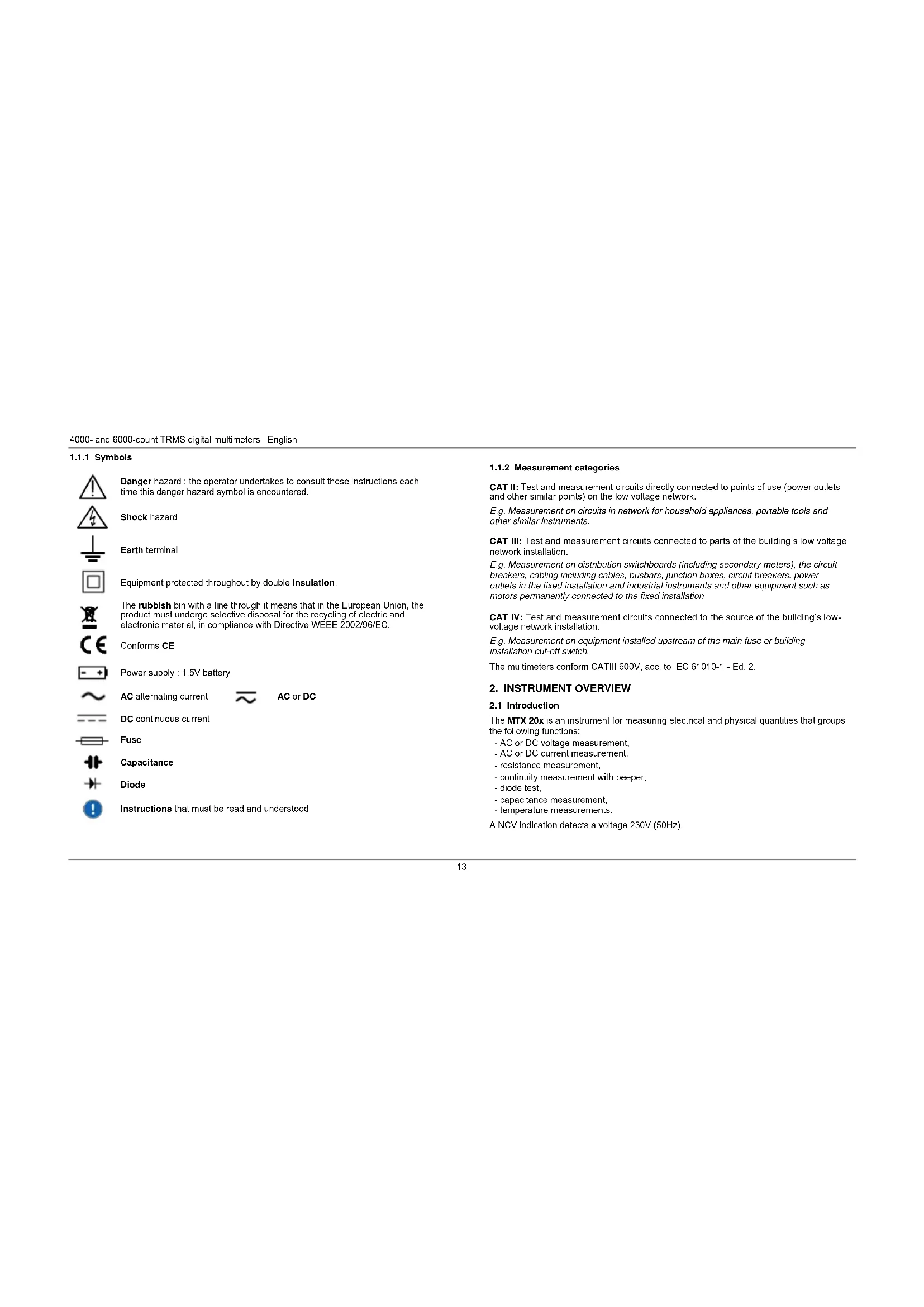
1.1.1 Symbols

Danger hazard : the operator undertakes to consult these instructions each time this danger hazard symbol is encountered.
Shock hazard

Earth terminal


Equipment protected throughout by double insulation.

The rubbish bin with a line through it means that in the European Union, the product must undergo selective disposal for the recycling of electric and electronic material, in compliance with Directive WEEE 2002/96/EC.

Conforms CE

Power supply : 1.5V battery

AC alternating current

AC or DC

DC continuous current

Fuse

Capacitance

Diode

Instructions that must be read and understood
1.1.2 Measurement categories
CAT II: Test and measurement circuits directly connected to points of use (power outlets and other similar points) on the low voltage network.
E.g. Measurement on circuits in network for household appliances, portable tools and other similar instruments.
CAT III: Test and measurement circuits connected to parts of the building's low voltage network installation.
E.g. Measurement on distribution switchboards (including secondary meters), the circuit breakers, cabling including cables, busbars, junction boxes, circuit breakers, power outlets in the fixed installation and industrial instruments and other equipment such as motors permanently connected to the fixed installation
CAT IV: Test and measurement circuits connected to the source of the building's low-voltage network installation.
E.g. Measurement on equipment installed upstream of the main fuse or building installation cut-off switch.
The multimeters conform CATIII 600V, acc. to IEC 61010-1 - Ed. 2.
2. INSTRUMENT OVERVIEW
2.1 Introduction
The MTX 20x is an instrument for measuring electrical and physical quantities that groups the following functions:
- AC or DC voltage measurement,
- AC or DC current measurement.
- resistance measurement,
- continuity measurement with beeper,
- diode test.
- capacitance measurement,
- temperature measurements.
A NCV indication detects a voltage 230V (50Hz).
English 4000- and 6000-count TRMS digital multimeters
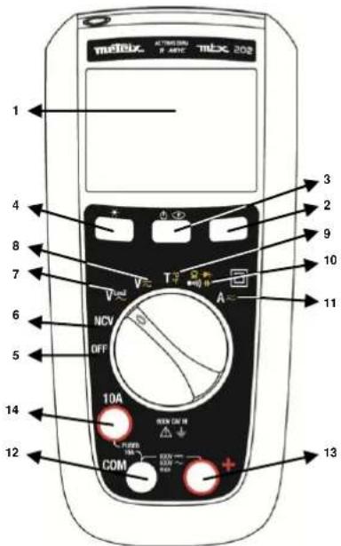
2.2 Device description
2.2.1. MTX 202
text_image
melbix ACTMENAMIC-melx 202
1 4 8 7 6 5 14 12 3 2 9 10 11 NCV OFF 10A COM +
gerous voltages may be present at the input terminals and may not be displayed.
| 1 | Display (See §. 2.3). |
| 2 | Range key: operative in VAC, VDC, VLOWZ, Ω, C, AAC, ADC ranges. |
| 3 | Yellow key: MODE AC/DCThe AC mode is selected (default) on V and DC is selected (default) on A.Switch to AC or DC mode by briefly pressing this key (short beep).The current mode is displayed on the LCD.To disable the Sleep mode, hold down [icon] during the meter on.Sleep mode is disabled and symbol (permanent) won't display any longer. |
| 4 | Hold key:Holds the display on the current value and froozes it (short press).A second short press returns the multimeter to normal mode.This key is operative in all ranges (excepted NCV). |
| 5 | OFF: power is off. |
| 6 | NCV: Non Contact Voltage Detection (230V) 50 Hz |
| 7 | VLowZ: Low impedance voltage measurement, AC |
| 8 | V AC/DC: voltage measurement (10MΩ), AC or DC |
| 9 | T: TK-thermocouple temperature measurement, in °C or in °F |
| 10 | OHM / CONTINUITY / DIODE / CAPACITANCE |
| 11 | A: current measurement in A, AC or DC |
| 12 | Common (return) terminal for all measurements |
| 13 | Input terminal for voltage, resistance, continuity, diode, capacitance, and temperature measurements (+) |
| 14 | Input terminal for AC and DC current measurement to 10A |
4000- and 6000-count TRMS digital multimeters English
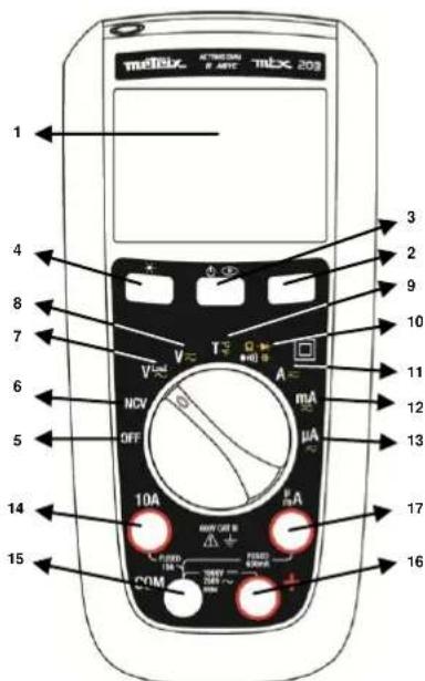
2.2.2 MTX 203
text_image
mELIX AT 1000000 mELX 20Ω 1 4 8 7 6 5 14 15 3 2 9 10 11 12 13 17 16 V T A V NCV OFF mA μA 10A PWM/CEM PUBO 100V 700V 700V 700V PWM
ngerous voltages may be present at the input terminals and may not be displayed.
| 1 | Display (See §. 2.3). |
| 2 | Range key: operative in VAC, VDC, VLOWZ, Ω, C, AAC, ADC ranges. |
| 3 | Yellow key: MODE AC/DCThe AC mode is selected (default) on V and DC is selected (default) on A.Switch to AC or DC mode by briefly pressing the same key (short beep).The current mode is displayed on the LCD.To disable the sleep mode : hold downturning the meter on.Sleep mode is disabled and symbol(permanent) won't display any longer. |
| 4 | Hold key:Holds the display on the current value and freezes it (short press).A second short press returns the multimeter to normal mode.This key is operative in all ranges (excepted NCV). |
| 5 | OFF: power is off. |
| 6 | NCV: Non Contact Voltage Detection (230V) 50 Hz |
| 7 | VLowZ: Low impedance voltage measurement, AC |
| 8 | V AC/DC: voltage measurement (10MΩ), AC or DC |
| 9 | T: TK-thermocouple temperature measurement, in °C or in °F |
| 10 | OHM / CONTINUITY / DIODE / CAPACITANCE: |
| 11 | A: current measurement in A, AC or DC |
| 12 | mA: current measurement in mA, AC or DC |
| 13 | μA: current measurement in μA, AC or DC |
| 14 | Input terminal for AC and DC current measurement to 10A |
| 15 | Common (return) terminal for all measurements |
| 16 | Input terminal for voltage, resistance, continuity, diode, capacitance,and temperature measurements |
| 17 | Input terminal for AC and DC microamps and milliamp measurements to 600mA |
Default Auto-range.
English 4000- and 6000-count TRMS digital multimeters
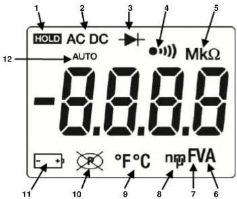
2.3 Display
text_image
1 2 3 4 5 HOLD AC DC AUTO -8.8.8.8 MKΩ - + 10 °F°C nm FVA 6 7| Item | Description | Item | Description |
| 1 | Display Hold is enabled. | 9 | F Farads for capacitance |
| 2 | AC, DC voltage or current | 10 | n, m, μ decimal prefix |
| 3 | Diode test is selected. | 11 | °F, °C temperature |
| 4 | Continuity is selected. | 13 | Autoshutdown is enabled. |
| 5 | M, k - decimal prefix | 14 | Battery is low and should be changed. |
| 8 | A, V - amps or volts | 16 | Auto measurement |
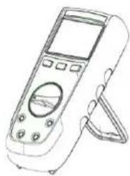
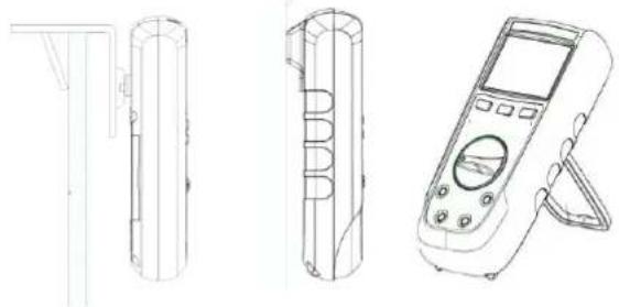
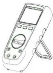
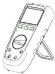
2.4 Fixation and stand
The meter can be used in different positions for a convenient and good reading:
- on the table
- on a wall, or an edge using P01102100Z DMM Multi fix accessory(optional)
- on a metallic door with our magnet-soft sheath
- with the stand
natural_image
Technical line drawings of three electronic devices: a cylindrical device, a segmented case, and a handheld device (no text or symbols present)4000- and 6000-count TRMS digital multimeters English
3. USE
3.1 First use
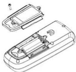
Place the batteries in the device as follows :
- Use a screwdriver, unscrew all the battery cover screws on the back of the meter.
- Place the batteries in the casing, respect polarity.
- Screw back battery cover screws.
It is recommended to follow this procedure when you use the meter for the first time, or after long time without use:
- Start the meter, make sure that all segments are displayed.
- Check that on Continuity position, and without any input the meter display OL.
• Take out both cords and short circuit, the beeper should sound. - Turn the rotary switch on V and check a known voltage (for example a battery) and make sure voltage is correct.
- When all the steps above are correct, you can start to use the meter.
3.2 Backlight and Torch light
When pressing the 1 for more than 2s, both LCD backlight (blue) and torch light (white) will light up.
Press again 10 more than 2s to shutdown the backlight.
On NCV position the backlight will blink red if AC live voltage is detected.
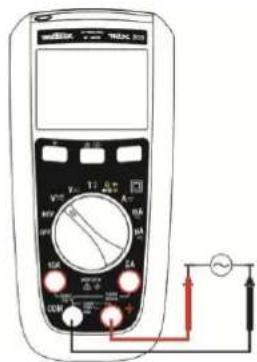
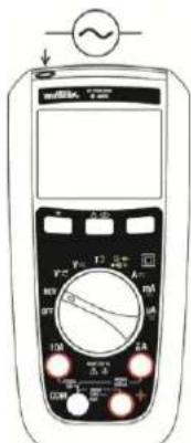
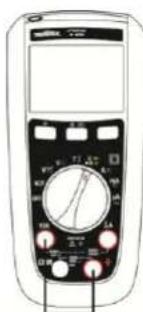
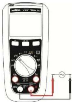
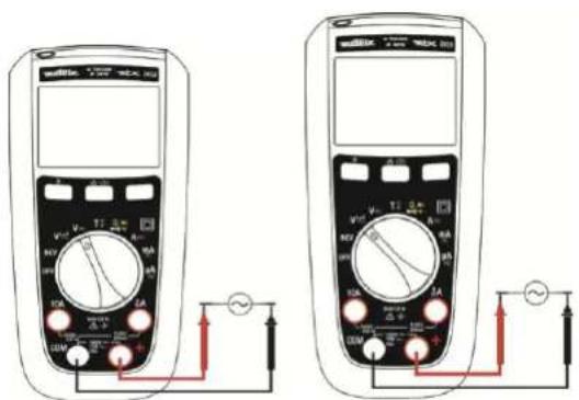
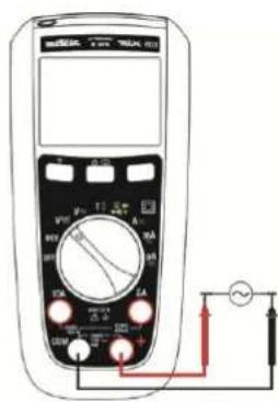
3.3 Measuring AC or DC voltages
The meter measures AC or DC voltage. To minimize risk when measuring an unknown voltage, make sure to measure both AC and DC voltage
- Turn the rotary switch to V≈ (10 MΩ), VLowZ ≈ (500 kΩ).
- Toggle between AC or DC voltage measurement by pressing the yellow button (in VlowZ: only AC measurement available).
- Connect the red test lead to the + terminal and the black test lead to the COM terminal.
- Measure the voltage by touching the probes to the desired test points of the circuit:
natural_image
Technical line drawing of a mobile phone casing with internal components (no text or symbols)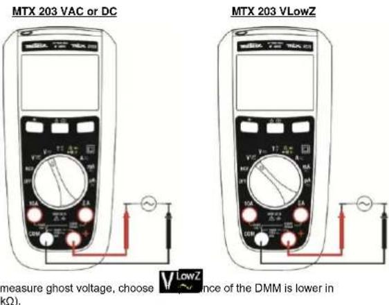
text_image
MTX 203 VAC or DC MTX 203 VLowZ measure ghost voltage, choose V LowZ ence of the DMM is lower in (Ω).English 4000- and 6000-count TRMS digital multimeters
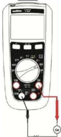
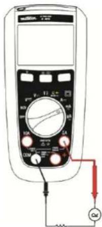
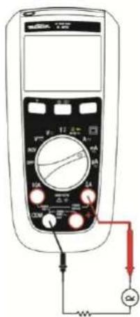
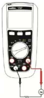
3.4 Measuring AC or DC current

TX 203 only , or


- Turn the switch to , or TX 203 only , or .
-
Toggle between AC or DC current measurement by pressing the yellow key.
-
Connect the red test lead to either A, or mA/μA terminal and black test lead to the COM terminal.
-
Break the circuit path to be measured. Then connect the test leads across the break and apply power.
-
Read the measured current on the display.
If current is above 10A, the DMM will sound. If current measured is above the rated current the fuse will blow.
MTX 202 and MTX 203
text_image
Diagram of a multimeter with labeled components including voltage source, switch, and measurement dialMTX 203
text_image
Diagram of a multimeter with labeled terminals and connections, including a voltmeter, pointer, and power supply connections.3.5 Measuring continuity

To avoid electrical shock and damage to the meter when measuring resistance or continuity in a circuit, make sure the power to the circuit is turned off and all capacitors are discharged.

power is disconnected from the
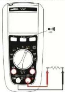
1. Turn the rotary switch to make the power is disconnected from the circuit to be measured.
2. Connect the red test lead to the + terminal and the black test lead to the COM terminal
3. Detect the continuity by touching the probes to the desired point of the circuit, if the resistance is under 50Ω, the beeper will sound, designating a short circuit. If the resistance is above 600Ω, the meter displays OL, designating an open circuit.
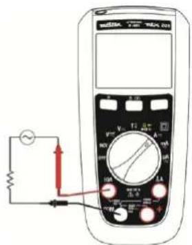
3.6 Measuring resistance

To avoid electrical shock and damage to the meter when measuring resistance or continuity in a circuit, make sure the power to the circuit is turned off and all capacitors are discharged.
With the continuity mode selected, press the yellow button once to activate the resistance measurement. Touch with the test probes the desired point of the circuit and read the measured resistance on the display.
If resistance is above 60MOhm the meter will display OL.
For MTX 202, above 40MOhm the meter will display OL.
text_image
Diagram of a multimeter with labeled components including a digital display, analog dial, and electrical connections4000- and 6000-count TRMS digital multimeters English
3.7 Testing Diodes

To avoid electrical shock and damage the meter when measuring diode in a circuit, make sure the power to the circuit is turned off and all capacitors are discharged.
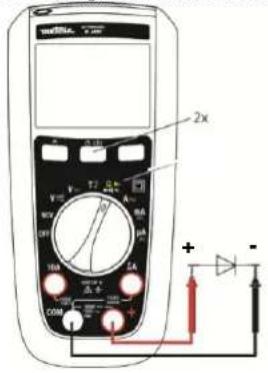
- Turn the rotary switch to make the power is disconnected from the circuit to be measured.
- Press the yellow button twice.
- Connect the red test probe to the anode side and black test lead to the cathode side of the diode being tested.
- Read the forward bias voltage value on the display.
- If the polarity of the test leads is reversed with diode polarity or forward bias voltage is above 3V, the display reading shows OL. This can be used to distinguish the anode and cathode sides of the diode
text_image
2x V A W R U T L A COM + - +3.8 Measuring Capacitance

To avoid electrical shock and damage to the meter when measuring capacitance in a circuit, make sure the power to the circuit is turned off and all capacitors are discharged.
Only Autorange is available in this mode.
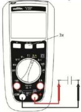
- Turn the rotary switch to make the power is disconnected from the circuit to be measured.
- Connect the red test lead to the + terminal and the black test lead to the COM terminal.
- Press the yellow button three times.
- Touch the probes to the capacitor leads.
- After allowing reading to stabilize, read the capacitance value on the display.
In the capacitance range 100mF the measure can be long and exceed 15s.
text_image
3x V M T1 A A R U U 100 1kA 1kA C D + - + - + - + - + - + - + - + - + - + - + - + - + -English 4000- and 6000-count TRMS digital multimeters
3.9 Measuring Temperature

To avoid electrical shock and damage to the meter when measuring a temperature, make sure that the surface in contact with the K thermocouple has no voltage.

- Turn the rotary switch to
- Toggle the yellow key to choose between °C and °F.
- Plug the K thermocouple into the + and COM terminal, insuring the thermocouple plug marked with a + symbol is connected to the + terminal.
- Read the temperature in degree on the display. While doing the measurement make sure to keep the meter within its working temperature.
After inserting the plug into the meter, allow 1 minute for thermal stabilization.
text_image
Diagram of a multimeter with labeled buttons and a pointer, showing measurement ranges and function dial.If no thermocouple the meter will display its internal temperature if above 0°C.
If temperature measured is above 1300°C the LCD will display OL.
3.10 Non Contact Voltage Detection (NCV)

NCV can only detect AC live voltage referenced to the ground, the Meter may not detect voltage in NCV due to installation condition of electrical circuit or equipment. Never touch the circuit under test to avoid possible danger even if the Meter didn't detect voltage in NCV.
Network : 230V only, 50 Hz (sensitivity : 10 mV)
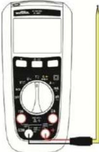
The meter can detect AC live voltage without contact.
-
Remove all test leads from the Meter
-
Turn the rotary switch to

- Approach live conductor from LCD (position of the Meter may affect measurement)
If no AC live voltage is detected the Meter will display EF and product will be silent.
If AC live voltage is detected product will show 4 different levels:
from - to ----, at - buzzer will sound discontinuously, at --- buzzer will sound continuously, and backlight will blink red. Basic detection voltage is for 220/230V.
NCV is only for indication purpose and shouldn't be used for measurement, or to detect the absence of voltage.
text_image
Diagram of a multimeter with analog dial and control buttons, showing measurement ranges and connections
The NCV mode has an indicative meaning only and must not be used either for measuring nor detect the absence of voltage.
An engraved marking on the sheath indicates the position of the antenna for NCV indication.
3.11 VlowZ
The Vlow Z position measures AC voltage with lower impedance (500kΩ) than normal voltage measurement, this function is used to avoid measuring ghost voltages.
4000- and 6000-count TRMS digital multimeters English
4. MAINTENANCE
The instrument has no parts that can be replaced by personnel who are not trained and approved. Any non-approved repair or other work, or replacement of a part by an "equivalent", may severely compromise safety
4.1 Cleaning
Periodically wipe the case with a damp cloth and mild detergent. Do not use abrasives or solvents. Dirt or moisture in the terminals can affect the readings. Dry the meter perfectly after cleaning and before use.
4.2 Testing the 10A Fuse

To avoid electrical shock, remove the test leads and any input signals before replacing the fuses.

- Turn the rotary switch to position and toggle the yellow key.
- Plug a test lead into the + terminal and touch the probe to the A or mA/μA according to the fuse to be tested A good A terminal fuse is indicated 000.0Ω to 000.2Ω.
- If the display reads OL, replace the fuse and test again
- If the display shows any other value, have the meter serviced.
text_image
Diagram of a multimeter with labeled controls and display screen4.3 Replacing the batteries and fuses

To avoid false readings, which could lead to possible electric shock, or personal injury, replace the batteries with LR6 batteries as soon as the battery indicator
- + appears.
To prevent damage of injury, install ONLY replacement fuses with the specified amperage, voltage, and interrupt ratings.
Disconnect test leads before opening the battery door.
F1: Fast Fuse 630mA 1000V 10kA size : 6.3 x 32, UK standard
F2: Fuse 10A 1000V 30kA size : 10 x 38, UK standard
4.4 Metrological check
Like all measuring or testing devices, the instrument must be checked regularly. This instrument should be checked at least once a year. For checks and calibrations, contact one of our accredited metrology laboratories (information and contact details available on request), at our Chauvin Arnoux subsidiary or the branch in your country.
4.5 Service, and Parts
For all repairs before or after expiry of warranty, please return the device to your distributor.
English 4000- and 6000-count TRMS digital multimeters
5. WARRANTY
Except as otherwise stated, our warranty is valid for 2 years starting from the date on which the equipment was sold. Extract from our General Conditions of Sale provided on request. The warranty does not apply in the following cases:
- Inappropriate use of the equipment or use with incompatible equipment
- Modifications made to the equipment without the explicit permission of the manufacturer's technical staff
• Work done on the device by a person not approved by the manufacturer - Adaptation to a particular application not anticipated in the definition of the equipment or not indicated in the user's manual
- Damage caused by shocks, falls, or floods.
6. TO ORDER
Delivered with
• a paper user's manual, 10 languages
• a set of 2 x 1.5V batteries AA
- Test lead elbowed 1,5 m red with ∅ 4 mm probe tips
• Test lead elbowed 1,5 m black with ∅ 4 mm probe tips
• K adaptor + sensor
Optional (references : consult http://www.chauvin-arnoux.com)
Probes
Set of Test lead RD/BK with test probes-elbowed male banana plugs PVC
Set of Test lead RD/BK with test probes-elbowed male banana plugs silicon Test probes cat III/IV
Crocodiles clips
Safety adapter and K sensor Temperature probe for multimeter
banana inputs with 18 mm spacing measurement from -50°C to +350°C
K sensor adapter and Temperature probe for multimeter
banana inputs with 18 mm spacing measurement from -50°C to +200°C
Miscellaneous
Carrying case
External charger for accu. 1.5V
Fuse
Fuse F 1000V 10A 10x38mm
Fuse F 1000V 0.63A 6.3x32mm
7. GENERAL SPECIFICATIONS
Mechanical features
Dimensions 170 x 80 x 50 mm
Weight 320 g (with batteries)
Packing blister 266 x 132 x 70 mm
Power supply
Batteries 2 x 1.5V AA
Battery life approx. 500 hours in VLowZ / VAC without backlight
Climatic conditions
Reference temp. 23°C ± 3°C
Use temperature -20°C to 55°C
Storage temp. -40°C to 60°C
Relative humidity < 90 % RH (up to 45°C) without condensation
Protection rating IP 54
Safety
Insulation class 2 double isolation
Pollution degree 2
Use indoor
Altitude < 2000 m
Category CAT III, 600 V max. to earth
EMC
8. TECHNICAL SPECIFICATIONS (See Appendix)
Referral conditions
Temperature +23°C ± 3°C.
Humidity 45% to 75% RH
Supply Full battery (no low bat signal display) or accu. 1.5 VAA Ni-MH
Freq. for AC signal 45-65 Hz
Pure AC signal
No other rotating magnetic field
No other electrical field
General measure characteristics
• in DC AC ≤0,1% of the DC signal
• in AC DC < 0,1% of the AC signal
INHALT
natural_image
Technical line drawings of four electronic devices: cylindrical, rectangular, and handheld device (no text or symbols)natural_image
Technical line drawing of a remote control casing with internal components and mounting holes (no text or symbols)text_image
Diagram of a multimeter with labeled terminals and connected to a power supply via a meter and resistor.MTX 203 VLowZ
text_image
Diagram of a multimeter with labeled components including voltage meter, scale, and connected resistorstext_image
Diagram of a multimeter with labeled components including voltage source, switch, and measurement dialMTX 203
text_image
Diagram of a multimeter with labeled terminals and connected to a power supply via a red circuit.text_image
Diagram of a multimeter with labeled terminals and connected circuitry, showing measurement ranges and connections.text_image
Diagram of a multimeter with labeled control panel and connected probe, showing measurement ranges and pointer connections.text_image
Diagram of a digital multimeter with labeled controls and dial indicatorsnatural_image
Technical line drawing of a cylindrical mechanical component with flanges and a side view (no text or symbols)
natural_image
Line drawing of a handheld electronic device with control panel and stand (no text or symbols)Multimetro digitale TRMS 4000- e 6000-punti Italiano
3. UTILIZZO
3.1. Primo utilizzo
natural_image
Technical line drawing of a mobile phone casing with internal components and connectors (no text or symbols)text_image
Diagram of a multimeter with labeled components including voltage source, switch, and measurement dialMTX 203
text_image
Diagram of a multimeter with labeled components including dial, power supply, and connected circuittext_image
Diagram of a multimeter with labeled components including a dial, power supply, and resistor connected to the right side.Multimetro digitale TRMS 4000- e 6000-punti Italiano
3.7. Test dei diodi

text_image
Diagram of a multimeter with labeled terminals and a probe connected to the right side, showing measurement ranges and pointer positions.text_image
Diagram of a digital multimeter with labeled control knobs and display screennatural_image
Technical line drawings of four different electronic devices or devices, shown from top to bottom views (no text or symbols present)text_image
Diagram of a multimeter with labeled components including voltage source, switch, and measurement dial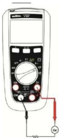
text_image
Diagram of a multimeter with labeled terminals and connected to an ammeter and voltmetertext_image
Diagram of a multimeter with labeled terminals and connected to a power source, showing measurement ranges and connections.text_image
Diagram of a multimeter with labeled control panel and probe, showing measurement ranges and pointer connectionstext_image
Digital multimeter device with analog dial and control buttons, showing measurement ranges and a close-up indicator.
text_image
Diagram of a multimeter with labeled controls and dial, showing measurement ranges and pointer positionsnatural_image
Technical line drawings of three electronic devices: a cylindrical device, a multi-chamber device, and a handheld device (no text or symbols present)3. POUŽITÍ
3.1 První použití
natural_image
Technical line drawing of a device casing with internal components and mounting holes (no text or symbols)text_image
Diagram of a multimeter with labeled components including a digital display, analog dial, and electrical connections3.7 Testování dlod

text_image
Diagram of a multimeter with labeled terminals and a probe connected to the right side, showing measurement ranges and pointer positions.natural_image
Front view of a digital multimeter with analog dial and control buttons (no visible text or labels)natural_image
Technical line drawing of a cylindrical mechanical component with flanges and a side view (no text or symbols)

natural_image
Line drawing of a handheld electronic device with control panel and display (no text or symbols)natural_image
Technical line drawing of a mobile phone casing with internal components and mounting holes (no text or symbols)3.2. Achtergrondverlichting en zaklamp
MTX 203 VAC of DC MTX 203 VLowZ
text_image
Diagram showing two multimeters connected to a power supply with labeled terminals and measurement probestext_image
Diagram of a multimeter with labeled components including voltage source, switch, and measurement dial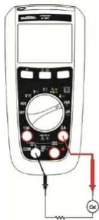
text_image
Diagram of a multimeter with labeled components including dial, buttons, and connected connections to an ammeter.text_image
Diagram of a multimeter with labeled components including a display, analog dial, and connected circuitrytext_image
Diagram of a multimeter with labeled control panel and connected probe, showing measurement setuptext_image
Front panel of a multimeter with analog dial and control buttons, showing measurement ranges and function labels- Adapter + sensor K
Als optle (referenties: ons raadplegen http://www.chauvin-arnoux.com)
Meetelementen
natural_image
Technical line drawing of a cylindrical mechanical component with flanges and a side view (no text or symbols)
natural_image
Line drawing of a handheld electronic device with a screen and stand (no text or symbols)natural_image
Technical line drawing of a mobile phone casing with internal components and mounting holes (no text or symbols)text_image
Diagram of a multimeter with labeled terminals and connected to a current meter showing measurement setup.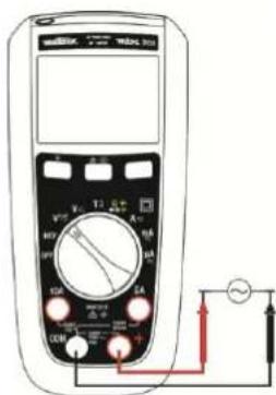
text_image
Diagram of a multimeter with labeled terminals and connected circuitry, showing measurement setuptext_image
Diagram of a multimeter with labeled components including voltage source, switch, and measurement dial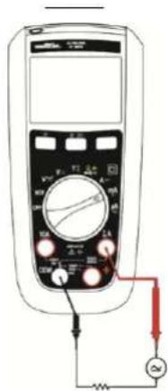
text_image
Diagram of a multimeter with labeled terminals and connected to an AC voltage source, showing measurement setup.text_image
Diagram of a multimeter with labeled components including a 12.5°C dial, connected to a resistor and ground connection.3.7. Test diod

text_image
Diagram of a multimeter with labeled function dial and probe connectionstext_image
Diagram of a multimeter with labeled controls and an AC input indicator showing voltage measurement.
text_image
Front panel of a digital multimeter with labeled buttons and dials for measurement or calibration.natural_image
Technical line drawings of four electronic devices: a cylindrical device, a multi-layered cylindrical device, a handheld phone with a display, and a separate view (no text or symbols present)Română
text_image
Diagram of a multimeter with labeled terminals and connected to a power supply circuitMTX 203 VLowZ
text_image
Diagram of a multimeter with labeled terminals and connected to a power supply meter showing AC current measurement setup.text_image
Diagram of a multimeter with labeled components including voltage source, switch, and measurement scaleMTX 203

text_image
Diagram of a multimeter with labeled terminals and connected to a power supply via a red circuit.text_image
Diagram of a multimeter with labeled components including voltage meter, switch, and power connectionsRomână
text_image
Diagram of a multimeter with labeled terminals and connected probe, showing measurement setuptext_image
Diagram of a multimeter with labeled controls and an AC input indicator showing ~sine symbol
text_image
Diagram of a multimeter with labeled dial and control buttons, showing measurement ranges and pointer positions.natural_image
Technical line drawing of a cylindrical mechanical component with flanges and a side arm (no text or symbols)
natural_image
Line drawing of a handheld electronic device with control panel and display (no text or symbols)natural_image
Technical line drawing of a remote control casing with internal components and mounting holes (no text or symbols)text_image
Diagram of a multimeter with labeled terminals and connected to a power supply via a red circuit.text_image
Diagram of a digital multimeter with labeled terminals and connected to a power supply circuit.
Русский
text_image
Diagram of a multimeter with labeled components including voltage source, switch, and resistance measurement setupMTX 203
text_image
Diagram of a multimeter with labeled components including scale, pointer, and connected connections to a power source.text_image
Diagram of a multimeter with labeled components including voltage meter, switch, and power connectionstext_image
Diagram of a multimeter with labeled control panel and connected probe, showing measurement ranges and pointer connections.text_image
Diagram of a multimeter with labeled function dial and control buttonsUnit 1 Nelson Ct - Flagship Sq - Shaw Cross Business Pk
DEWSBURY, West Yorkshire - WF12 7TH
Tel: 01924 460 494 - Fax: 01924 455 328
CHINA - Shanghai Pujiang Enerdis Instruments Co. Ltd
3 Floor, Building 1 - N° 381 Xiang De Road
Hongkou District - 200081 SHANGHAI
Tel: +86 21 65 21 51 96 - Fax: +86 21 65 21 61 07
中国-上海浦江埃纳迪斯仪表有限公司
上海市虹口区祥德路381号3号楼3楼
Tel: +86 21 65 21 51 96 - Fax: +86 21 65 21 61 07
ITALIA - Amra SpA
Via Sant'Ambrogio, 23/25 - 20846 MACHERIO (MB)
Tel: 039 245 75 45 - Fax: 039 481 561
ESPAÑA - Chauvin Arnoux Ibérica S.A.
C/ Roger de Flor, 293 - 1a Planta - 08025 BARCELONA
Tel: 902 20 22 26 - Fax: 934 59 14 43