MX 650 - Multimeter METRIX - Free user manual and instructions
Find the device manual for free MX 650 METRIX in PDF.
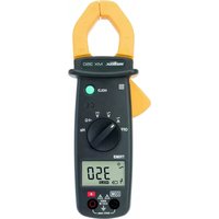
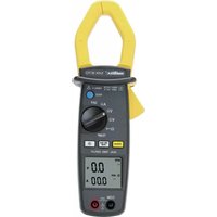
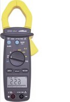
| Product Type | ACrms/DC 4000-count clamp multimeter |
| Brand | Metrix |
| Model | MX 650 |
| Display | Digital 3 ¾ digits (max 3999) + 42-segment bargraph |
| Installation Category | CAT III 600 V |
| Pollution Degree | 2 |
| Power Supply | 9 V battery (NEDA 1604, 6F22, 006P or alkaline) |
| Typical Battery Life | 180 hours (with alkaline battery, without buzzer) |
| Dimensions | 246 × 93 × 43 mm |
| Weight | 400 g (with battery) |
| Maximum Jaw Opening | 36 mm |
| Protection Rating | IP30 |
| Measurement Functions | AC/DC voltage, AC current (clamp), resistance, continuity, diode test, frequency (voltage and current) |
| Special Functions | PEAK (1 ms), MAX/MIN (500 ms), HOLD, REL (relative zero), auto/manual ranging, auto power off (30 min) |
| Safety | Follow the instructions in the manual; do not exceed the rated limits; use CAT III/IV probes |
| Maintenance and Cleaning | Disconnect the device, clean with a damp cloth and soap; do not use abrasive products or solvents |
| Warranty | 1 year against defects in material or workmanship (excluding improper use) |
| Package Contents | 1 clamp multimeter, 1 set of test leads (red + black), 1 9 V battery, 1 case, 1 manual, 1 verification certificate |
Frequently Asked Questions - MX 650 METRIX
User questions about MX 650 METRIX
0 question about this device. Answer the ones you know or ask your own.
Ask a new question about this device
Download the instructions for your Multimeter in PDF format for free! Find your manual MX 650 - METRIX and take your electronic device back in hand. On this page are published all the documents necessary for the use of your device. MX 650 by METRIX.
USER MANUAL MX 650 METRIX
Chapter II - page 16
Bedienungsanleitung
text_image
Diagram of a multimeter connected to a power supply with labeled 12V measurement points and a probenatural_image
Diagram showing a handheld device connected to an electrical circuit board (no text or symbols present)text_image
Diagram of two analog multimeters with labeled probes and dials, showing measurement setup for digital display and probe connections.text_image
Diagram of a digital multimeter with labeled components including power supply, switch, and digital displaytext_image
Diagram of a digital multimeter with measurement scale and waveform indicator1.1. Precautions and safety measures ..... 17
1.1.1. Before using 17
1.1.2. When using the instrument.... 17
1.1.3. Symbols.... 17
1.1.4. Instructions.... 18
1.1.5. Cleaning 18
1.2. Warranty 18
1.3. Maintenance.... 18
1.4. Unpacking - Repacking 18
2. DESCRIPTION OF THE INSTRUMENT....19
2.1. Description of front and rear 19
2.2. Description of the display.... 20
3. GENERAL DESCRIPTION....21
3.1. Battery installation and replacement....21
3.2. Zero function and relative measurement ..... 21
3.3. Memory 21
3.4. Automatic range 21
3.5. Auto cut-off 21
3.6. PEAK function (1 ms) 22
3.7. MAX MIN function (500 ms)....22
4. FUNCTIONAL DESCRIPTION 22
4.1. Measuring AC voltage 22
4.2. DC voltage measurement 23
4.3. Measuring AC current.... 23
4.4. Measurement of direct current (MX 655 only).... 24
4.5. Measuring resistance 24
4.6. Continuity test with buzzer 25
4.7. Diode test 25
4.8. Measurement of the voltage frequency.... 26
4.9. Measurement of the current frequency 26
5. TECHNICAL SPECIFICATIONS 27
5.1. General 27
5.2. Characteristics.... 27
5.2.1. Direct voltage (automatic ranges)...... 27
5.2.2. Alternating voltage (automatic ranges) ..... 27
5.2.3. Direct current (MX 655 only).... 27
5.2.4. Alternating current 28
5.2.5. Resistance (Ω) (automatic ranges)...... 28
5.2.6. Diode 28
5.2.7. Frequency Hz (automatic ranges) 28
5.3. Safety 28
5.4. General information 29
5.5. Environmental conditions....29
5.5.1. Temperature 29
5.5.2. E.M.C. 29
5.6. Delivery configuration 29
1. GENERAL INSTRUCTIONS
1.1. Precautions and safety measures
1.1.1. Before using
You have just acquired a 4,000-count multimeter clamp. We thank you for your confidence.
This multimeter clamp complies with the IEC 61010 norms concerning electronic measuring instruments. For your own safety and to prevent damage to the instrument, you must follow the instructions given in this manual.
* This instrument can be used for measuring category III installation circuits, in an environment with a pollution degree of 2 and with a voltage no higher than 600V in relation to the earth.
* Definition of the installation categories (see IEC 61010-1 publication):
CAT I: CAT I circuits are circuits protected by low level transient -voltage surge limiters. Example: protected electronic circuits
CAT II: CAT II circuits are household or similar appliance power circuits, which may carry medium-level transient voltage surge. Example: household appliance and portable tool power supplies
CAT III: CAT III circuits are high-power appliance power circuits, which may carry high-level transient voltage surges. Example: industrial machinery or instrument power supplies
CAT IV: CAT IV circuits are circuits which can carry very substantial transient -voltage surges. Example: power feeders
The mounted probes must have an assigned measurement category III or IV according to IEC 61010-031 and a rated voltage rated at least equal to 1000 V.
Before using, always check that they are in perfect working order.
1.1.2. When using the instrument
- Never exceed the protection limit values indicated in the specifications for each type of measurement.
- When the multimeter clamp is linked to the measurement circuits, do not touch any unused terminals.
- Before changing the function, disconnect the measurement leads from the circuit measured.
- Never measure resistances on a live circuit.
1.1.3. Symbols

Refer to the user's manual

Risk of electric shock

Double insulation
1.1.4. Instructions
- Before opening the instrument, disconnect it from the measuring circuits and make sure that you are not charged with static electricity, which could irreparably damage the instrument's internal elements.
- A "qualified person" is someone who is familiar with the installation, the construction, the application and the dangers at hand. This person is authorised to power up and power down the installation and equipment, in compliance with safety regulations.
1.1.5. Cleaning
Turn off the power supply. Clean with a damp cloth and soap. Never use abrasive products or solvents.
1.2. Warranty
This equipment is guaranteed against any material or manufacturing defects, in accordance with the general conditions of sale.
During the warranty period (1 year), the instrument can only be repaired by the manufacturer, who reserves the right to repair the instrument or to exchange all or part of it. If the equipment is returned to the manufacturer, the outgoing transport costs are borne by the customer.
The warranty is not applicable in the following cases:
- improper use of the equipment or use of it in conjunction with incompatible equipment;
- modifications to the equipment without the explicit authorisation of the manufacturer's technical department;
- work carried out on the instrument by a person not approved by the manufacturer;
- adaptation for a specific application, not included in the definition of the equipment or the user's manual
- knocks, falls or flooding.
The contents of this manual must not be reproduced in any form without our consent.
1.3. Maintenance
Return your instrument to your distributor for any work to be done within or outside the guarantee.
1.4. Unpacking - Repacking
All the equipment was checked mechanically and electronically before shipment. Every precaution was taken to ensure that you receive the instrument undamaged. It is a good idea to check quickly to detect any damage that may have occurred during transport. If there is any damage, immediately notify the transporter of the customary reservations.
Caution! If you ship this instrument on elsewhere, use preferably the original packaging and indicate the reasons for reshipment as clearly as possible in a note enclosed with the equipment.
2. DESCRIPTION OF THE INSTRUMENT
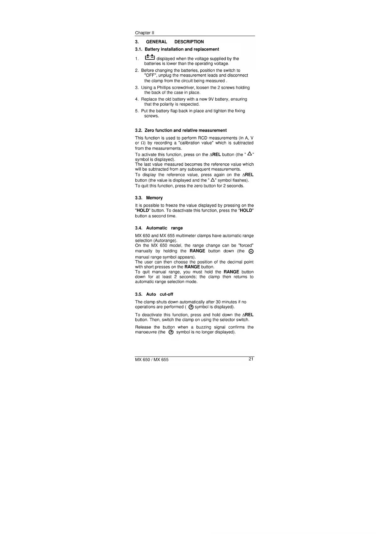
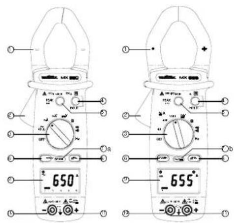
2.1. Description of front and rear
text_image
EC 100 POLLAR ELECTRIC VOLVER TOM BANANA ELECTRIC SHORT CAPACING RIP PUMP ONION ELECTRIC CE RIP PUMP HOLD OUT RISP. COM PUMP ONION ELECTRIC DURATION FOR SMALL T 12| 1 | Jaws |
| 2 | Trigger |
| 3 | Selector switch |
| 4 | HOLD button |
| 5 | PEAK button |
| 6 | MIN / MAX button |
| 7a | RANGE button |
| 7b | AC/DC button |
| 8 | ΔREL button |
| 9 | Display |
| 10 | COM input terminal |
| 11 | + input terminal |
| 12 | Battery housing |
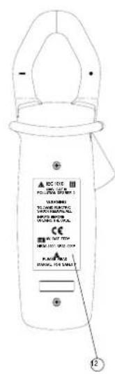
2.2. Description of the display
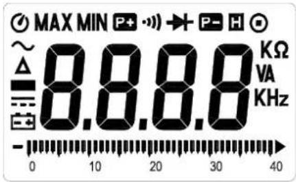
text_image
MAX MIN P+ → P- H ~ 8.8.8.8 KΩ Δ VA KHz 0 10 20 30 40| MX 650 | MX 655 | ||
| ● | ● | Auto cut-off | |
| ● | ● | MAX | Max. value |
| ● | ● | MIN | Min. value |
| ● | ● | Positive peak | |
| ● | ● | Continuity test | |
| ● | ● | Diode test | |
| ● | ● | Negative | |
| ● | ● | Hold | |
| ● | ● | Manual range | |
| ● | ● | Resistance measurement | |
| ● | ● | V | Voltage measurement |
| ● | ● | A | Current measurement |
| ● | ● | Hz | Frequency measurement |
| ● | ● | K | Kilo |
| ● | ● | Bargraph | |
| ● | ● | Batteries down | |
| ● | Direct current | ||
| ● | ● | Negative value | |
| ● | ● | Zero function and relative measurement | |
| ● | ● | Alternating current |
peak
3. GENERAL DESCRIPTION
3.1. Battery installation and replacement
- displayed when the voltage supplied by the batteries is lower than the operating voltage.
- Before changing the batteries, position the switch to "OFF", unplug the measurement leads and disconnect the clamp from the circuit being measured.
- Using a Phillips screwdriver, loosen the 2 screws holding the back of the case in place.
- Replace the old battery with a new 9V battery, ensuring that the polarity is respected.
- Put the battery flap back in place and tighten the fixing screws.
3.2. Zero function and relative measurement
This function is used to perform RCD measurements (in A, V or ) by recording a "calibration value" which is subtracted from the measurements.
To activate this function, press on the REL button (the " " symbol is displayed).
The last value measured becomes the reference value which will be subtracted from any subsequent measurements.
To display the reference value, press again on the REL button (the value is displayed and the " " symbol flashes).
To quit this function, press the zero button for 2 seconds.
3.3. Memory
It is possible to freeze the value displayed by pressing on the "HOLD" button. To deactivate this function, press the "HOLD" button a second time.
3.4. Automatic range
MX 650 and MX 655 multimeter clamps have automatic range selection (Autorange).
On the MX 650 model, the range change can be "forced" manually by holding the RANGE button down (the manual range symbol appears).
The user can then choose the position of the decimal point with short presses on the RANGE button.
To quit manual range, you must hold the RANGE button down for at least 2 seconds; the clamp then returns to automatic range selection mode.
3.5. Auto cut-off
The clamp shuts down automatically after 30 minutes if no operations are performed ( Ⓞ symbol is displayed).
To deactivate this function, press and hold down the REL button. Then, switch the clamp on using the selector switch.
Release the button when a buzzing signal confirms the manoeuvre (the ⏻ symbol is no longer displayed).
3.6. PEAK function (1 ms)
This function enables 1 ms voltage or current PEAK signals to be captured.
Before a signal is captured, the clamp must first be calibrated by holding the PEAK button down for more than 2 seconds, until "CAL" is displayed, indicating that the offset has been correctly taken into account.
Choose the positive or negative sign of the peak (P+ or P-) with short presses on the PEAK button.
To quit the manual range, you must hold the RANGE (MX 650) or the i = (MX 655) button down for at least 2 seconds; the clamp then returns to normal mode.
3.7. MAX MIN function (500 ms)
To activate the MAX MIN function, press on the MAX MIN button. The MAX value is then displayed.
If you press on the button again, the MIN value will be displayed.
If you press on the button a third time, the instantaneous measurement is displayed (however, the "MAX MIN" symbol flashes, indicating that the function is still active).
To quit the manual range, you must hold the MAX MIN button down for at least 2 seconds; the clamp then returns to normal mode.
4. FUNCTIONAL DESCRIPTION
4.1. Measuring AC voltage
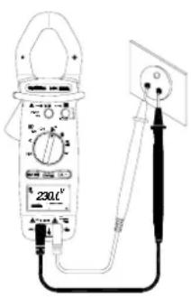
text_image
230kF 230kF- (MX 650) Position the switch to V.
- (MX 655) Position the switch to ≈V. The symbol ∼ (alternating signal) should be displayed. If not, press on the ∼=button, to make it appear.
Connect the red test lead to the "+" input terminal and the black test lead to the "COM" input terminal.
Then place the touch prods in contact with the points where the AC voltage is to be measured.
Then read the result on the display.
4.2. DC voltage measurement
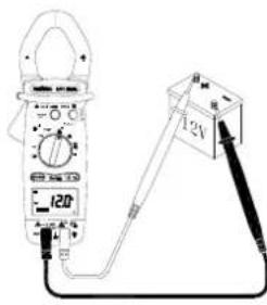
text_image
120 12V- (MX 650) Set the switch to ==V.
• (MX 655) Set the switch to ≅V.
Press on the ∼/=button to display the === symbol (direct signal).
Connect the red test lead to the "+" input terminal and the black test lead to the "COM" input terminal.
Then place the touch prods in contact with the points where the DC voltage is to be measured.
Then read the result on the display.
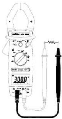
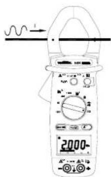
4.3. Measuring AC current
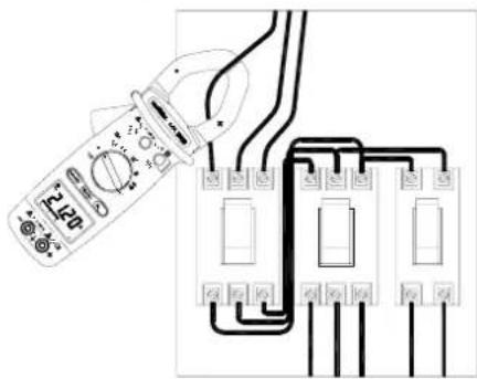
text_image
Diagram showing a multimeter connected to three electrical circuit breakers with labeled components- (MX 650) Set the switch to A (corresponding to the 1000 A\~ and 400 A\~ automatic calibres).
- (MX 655) Set the switch to 1000 A ≈. The \~symbol (alternating signal) should be displayed. If not, press on the ∼=button, to make it appear.
Open the clamp jaws by pressing the trigger. Position the clamp around the conductor to be measured.
Release the trigger. Check the clamp is properly closed. Read the result of the measurement on the display.
If reading is difficult, press the HOLD button and read the result afterwards.
If necessary, for better resolution you can move to a lower range by means of the selector switch.
Note: For safety reasons, disconnect the measuring leads before measuring current. The clamp should encircle only one conductor, otherwise the measurement result may be incorrect. The best measurement is obtained with the conductor centred in the middle of the jaws.
4.4. Measurement of direct current (MX 655 only)
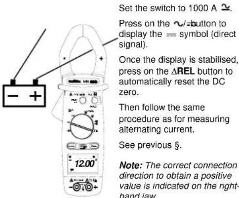
text_image
Set the switch to 1000 A ≈. Press on the ∼ button to display the == symbol (direct signal). Once the display is stabilised, press on the ΔREL button to automatically reset the DC zero. Then follow the same procedure as for measuring alternating current. See previous §. Note: The correct connection direction to obtain a positive value is indicated on the right- hand jaw.4.5. Measuring resistance
text_image
3000° A-1000 A-5000Set the switch to .
Connect the red test lead to the "+" input terminal and the black test lead to the "COM" input terminal.
Place the touch prods in contact with the points to be measured and read the result on the display.
Note: Always ensure that the circuit is disconnected from the power supply before measuring resistance!
To measure low resistances, it is preferable to offset the resistance of the measurement leads.
To do this, short-circuit the lead touch prods then press the REL button before taking the measurements.
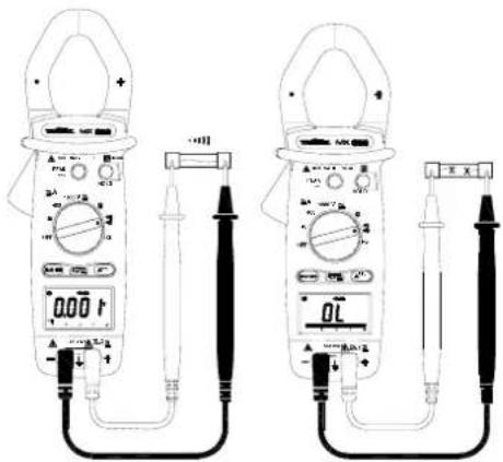
4.6. Continuity test with buzzer
text_image
Technical line drawing of two analog multimeters with digital display and probe connections, showing measurement setup.Set the switch to ▶:)))
Connect the red test lead to the "+" terminal and the black to the "COM" terminal.
Put the touch prods into contact with the circuit to be tested. If the resistance is less than R < 75 ± 25 , the buzzer will make a continuous sound.
Note : Always ensure that the circuit is disconnected from the power supply before measuring continuity! To offset lead resistance, short circuit the lead touch prods, then press on the REL button.
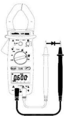
4.7. Diode test
text_image
0500Set the switch to Connect the red test lead to the "+" terminal and the black test lead to the "COM" terminal.
Put the red touch prod into contact with the diode anode and the black prod into contact with the cathode.
Read the value of its threshold voltage off the display.
Note: Always ensure that the circuit is disconnected from the power supply before testing diodes! If the connection is made back to front, the display indicates "OL" (Overload); this enables the user to distinguish the anode from the cathode.
4.8. Measurement of the voltage frequency
text_image
Diagram of a digital multimeter with labeled components and connected probes, showing measurement ranges and terminal connections.Set the switch to "Hz".
Connect the red test lead to the "+" terminal and the black test lead to the "COM" terminal.
Place the touch prods in contact with the points whose frequency is to be measured.
Read the result on the display.
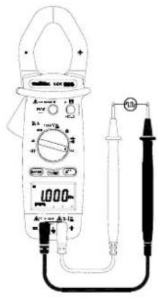
4.9. Measurement of the current frequency
text_image
Diagram of a digital multimeter with labeled components and measurement scale showing 2000Ω valueSet the switch to "Hz".
Open the clamp by pressing the trigger.
Encircle the conductor and close the jaws correctly by releasing the trigger.
Read the result on the display.
Note: For safety reasons, disconnect the clamp measuring leads before measuring current frequency. The clamp should encircle only one conductor, otherwise the measurement result may be incorrect.
Note: To measure frequency, either the input terminals (voltage) or the clamp jaws (current) can be used, but the two sources should never be used at the same time.
5. TECHNICAL SPECIFICATIONS
5.1. General
Only the values assigned tolerances or the limits declared constitute guaranteed values. The values without any tolerance are given as indications.
The symbol 0L is displayed when input signal exceeds measuring limit in 40 A\~ (MX 650), 40 and 400 A\~ (MX 655), resistance and continuity range.
In voltage, current and frequency range, this symbol will not be shown even the read reach the measuring limit of : 750 VAC, 1000 VDC, 1000 AAC/DC, 10 Hz.
5.2. Characteristics
Accuracy is to within ± [% of the reading (L) + number of counts (ct)] in the reference conditions indicated in the appendix.
(MX 655) When measuring U rms and I rms, add ± 1% L additional error margin, from 5% to 50% of the range for a maximum peak factor of 6, and from 5% to 100% of the range for a peak factor of between 1.4 and 3.
Over and above these limits, accuracy is not specified.
5.2.1. Direct voltage (automatic ranges)
(MX 650)
| Range | Meas. | range | Resolution | Accuracy |
| 400 V 0.2 to | 399.9 V 0.1 V 0.75% L + 2 ct | |||
| 1000 V 400 to | 1000 V 1 V 0.75% L + 2 ct | |||
Protection against overloads: 1000 Vrms
(MX 655)
| Range | Meas. | range | Resolution | Accuracy |
| 400 V 0.2 to | 399.9 V 0.1 V 1% L | + 2 ct | ||
| 1000 V 400 to | 1000 V 1 V 1% L | + 2 ct |
Protection against overloads: 1000 Vrms
5.2.2. Alternating voltage (automatic ranges)
(MX 650)
| Range | Meas. range | Frequency | Respl. Accuracy |
| 400 V | 0.5 to 399.9 V | 50...500 Hz500...1000 Hz | 0.1 V 1.2% L + 5 ct1.5% L + 5 ct |
| 750 V 400 V | 0 to 750 V 50 | 50...500 Hz500...1000 Hz | 1 V 1.2% L + 5 ct1.5% L + 5 ct |
Input impedance: 10 MΩ
Protection against overloads: 1000 Vrms
(MX 655)
| Range | Meas. range | Frequency | Resol. | Accuracy |
| 400 V | 0.5 to 399.9 V | 50...500 Hz500...1000 Hz | 0.1 V | 1.5% L + 5 ct1.8% L + 5 ct |
| 750 V | 40 to 750 V | 50...500 Hz500...1000 Hz | 1 V | 1.5% L + 5 ct1.8% L + 5 ct |
Input impedance: 10 MΩ
Protection against overloads: 1000 Vrms
5.2.3. Direct current (MX 655 only)
| Range | Meas. range | Resolution | Accuracy |
| 40 A 0.10 to 39.99 A | 0.01 A | 2.5% L + 10 ct | |
| 400 A 40.0 to 400.0 A | 0.1 A | 2.5% L + 10 ct | |
| 1000 A | 400 to 1000 A 1 A | 2.5% L + 10 ct |
Protection against overloads: 1200 ARMS
5.2.4. Alternating current
(MX 650 automatic ranges)
| Range | Meas. range | Frequency | Resol. | Accuracy | |
| 40 A 0.05 | to 39.99 A | 50...500 Hz | 0.01 A | 1.9% L + 5 ct | |
| 500...1000 Hz | 3% L + 5 ct | ||||
| 400 A 40.0 | to 400.0 A | 50...500 Hz | 0.1 A | 1.9% L + 5 ct | |
| 500...1000 Hz | 3% L + 5 ct | ||||
| 1000 A 400 | to 1000 A | 50...500 Hz | 1 A | 1.9% L + 5 ct | |
| 500...1000 Hz | 3% L + 5 ct | ||||
Protection against overloads: 1000 ARMS
(in 40 A range) and 1500 Arms (in 400 A and 1000 A ranges)
(MX 655)
| Range | Meas. range | Frequency | Resol. | Accuracy | |
| 40 A 0.05 to 39.99 A 50...60 Hz | 0.01 A | 1.9% L + 5 ct2.5% L + 5 ct3.5% L + 5 ct | |||
| 400 A* 40.0 to 400.0 A 50...60 Hz | 0.1 A | 1.9% L + 5 ct2.5% L + 5 ct3.5% L + 5 ct | |||
| 1000 A* 400 to 1000 A | 50...60 Hz60...500 Hz500...1000 Hz | 1 A | 1.9% L + 5 ct2.5% L + 5 ct3.5% L + 5 ct | ||
Protection against overloads: 1200 ARMS
*Position \~A on the switch corresponds to the two
automatic calibres, 400 A\~ and 1000 A\~.
5.2.5. Resistance (Ω) (automatic ranges)
| Range | Meas. range | Resolution | Accuracy |
| 400 Ω | 0.2 to 399.9 Ω | 0,1 Ω | 1%L + 3 ct |
| 4000 Ω | 400 to 4000 Ω | 1 Ω | 1%L + 2 ct |
Protection against overloads: 600 Vrms
Continuity detection threshold: R < 75 Ω ± 25 Ω.
5.2.6. Diode
| Test current | Open circuit voltage | |
| MX 650 | 0.6 mA | max .3 V |
| MX 655 | max 1.7 mA | max 6 V |
Protection against overloads: 600 Vrms
5.2.7. Frequency Hz (automatic ranges)
- For current
| Range | Meas. range | Resol. | Accuracy | Sensitivity |
| 4000 Hz | 20 to 3999 Hz | 1 Hz | 0.1% L + 1 ct | 2 ARMS |
| 10 kHz | 4 to 10 kHz | 10 Hz | 0.1% L + 1 ct | 5 ARMS |
- For voltage
| Range | Meas. range | Resol. | Accuracy | Sensitivity |
| 4000 Hz | 10 to 3999 Hz 1 Hz | 0.1% L + 1 ct | 5 Vrms | |
| 10 kHz | 4.00 to 10.00 kHz | 10 Hz | 0.1% L + 1 ct | 10 Vrms |
5.3. Safety
IEC 61010-1 and IEC 61010-2-032 :
- Insulation: class II
- Pollution level: 2
- Altitude: < 2000 m
- Installation category: CAT III 600 V
5.4. General information
Digital display
3 34 digit LCD with max. reading of 3,999 counts
Analogue display
42-segment bargraph
Polarity
When a negative signal is applied, the ■ signal appears.
Low battery indicator
is displayed when the voltage supplied by the batteries is lower than the operating voltage. Measurements are no longer guaranteed.
Power supply
Battery: 9 V, NEDA 1604, 6F22, 006P or alkaline
Typical autonomy: 180 hours (MX 650)
36 hours (MX 655)
with alkaline battery and without buzzer function.
Protection level of the housing
IP30 according to NF EN 60529
Maximum jaw opening
MX 650: ∅ 36 mm
MX 655: ∅ 40 mm
Dimensions
246 x 93 x 43 mm
Weight
400 g (with battery)
5.5. Environmental conditions
5.5.1. Temperature
Operation: 0°C to 40°C, < 70 % RH
Storage: -10^ to 60^ , < 80 % RH
5.5.2.E.M.C.
Immunity: acc. to EN 61326
Emission: acc. to EN 61326
5.6. Delivery configuration
Instrument delivered with:
1 set of measuring leads (one black, one red)
1 x 9 V alkaline battery
1 carrying case
1 user's manual
1 verification certificate
APPENDIX: Reference conditions
Sine signal:
- Frequency from 48 to 65 Hz
- No continuous components
Temperature 23°C ± 5°C
External magnetic field < 40 A/m
No alternating magnetic field
Measured conductor centred (in A)
INHALTSVERZEICHNIS
text_image
Diagram of a multimeter measuring an electrical outlet with labeled scale and probe connectionstext_image
Diagram showing a multimeter connected to an electrical circuit with labeled components and wiring connectionstext_image
Diagram of two analog multimeters with digital dials and probes, showing measurement setup for reading or testing.text_image
Diagram of a digital multimeter with labeled components including power supply, test probes, and digital displaynatural_image
Illustration of a multimeter connected to a 12V power supply via a tool (no text or symbols visible)text_image
Diagram showing a multimeter connected to three electrical components with labeled terminals and wiringtext_image
Technical line drawing of two analog multimeters with labeled probes and dials, showing measurement setup for digital display and probe connections.text_image
Diagram of a digital multimeter with labeled components including a reading display and connected probestext_image
Diagram of a digital multimeter with measurement scales and a waveform indicator showing current flow.text_image
ICU 100 WARNING STANDARD CODE PANCING THIS ALL INTRODUCTION ORANGE THIS CODE CE FOR START WARNING THIS CODE START FOR WARNING THIS CODE 12| 1 | Mordazas |
| 2 | Gatillo |
| 3 | Conmutador |
| 4 | Tecla HOLD |
| 5 | Tecla PEAK |
| 6 | Tecla MIN / MAX |
| 7a | Tecla RANGE |
| 7b | Tecla AC/DC |
| 8 | Tecla ΔREL |
| 9 | Display |
| 10 | Borne de entrada COM |
| 11 | Borne de entrada + |
| 12 | Alojamiento bateria |