MX 355 - Multimeter METRIX - Free user manual and instructions
Find the device manual for free MX 355 METRIX in PDF.
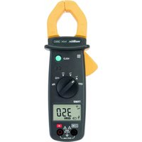
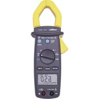
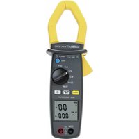
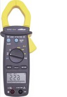
| Product Type | TRMS AC/DC Digital Clamp Multimeter |
| Brand | Metrix (Chauvin Arnoux) |
| Model | MX 355 |
| Dimensions | 199 x 75 x 36 mm |
| Weight | 243 g (with batteries) |
| Power Supply | 2 x 1.5 V AAA/LR03 batteries |
| Battery Life | Approx. 40 hours (MX 355) |
| Display | 6000-count LCD |
| TRMS Measurement | True RMS, sampling 2 measurements/s |
| Max Jaw Opening | 30 mm |
| Measurement Category | 600 V CAT III |
| Max Voltage (AC/DC) | 600 V |
| Max AC Current | 400 A |
| Max DC Current | 400 A |
| Max Resistance | 600 Ω |
| Continuity Test | Yes (threshold ≤ 35 Ω typical, buzzer) |
| Special Functions | Hold, Peak (1 ms), Delta (relative zero) |
| Auto Range | Yes |
| Auto Power Off | Yes, after 20 minutes |
| Safety | Double insulation, class II, IP30 |
| Included Accessories | Set of leads, 2 batteries, carrying case, attestation |
| Cleaning | Soft cloth lightly dampened with soapy water, no solvent |
| Warranty | 24 months |
Frequently Asked Questions - MX 355 METRIX
User questions about MX 355 METRIX
0 question about this device. Answer the ones you know or ask your own.
Ask a new question about this device
Download the instructions for your Multimeter in PDF format for free! Find your manual MX 355 - METRIX and take your electronic device back in hand. On this page are published all the documents necessary for the use of your device. MX 355 by METRIX.
USER MANUAL MX 355 METRIX
text_image
8 HOLD CE OFF Hz TRMS -4 kHz -0.000A V COM Δ RHT CAT1 +1 RHT FOR 7 1 2 3 4 5 6 HOLD PEAK FRAE 1 Δ ZERO OFF TRMS -4 kHz -0.000A V COM Δ RHT CAT1 +1 RHT FORnatural_image
Technical line drawing of a remote control device with battery pack and housing (no text or symbols)text_image
Diagram of a digital multimeter connected to a power supply with labeled components and measurement scaletext_image
Diagram showing a multimeter connected to three electrical components with labeled terminals and wiring connections\~A
text_image
Diagram showing two identical analog multimeters connected to a digital display, with terminal labels and measurement scales.text_image
I 50.0 1200 AOC 3800 HOLD CE OFF HIO HIO TIMES1.1. Precautions and safety measures . 17
1.1.1. Symbols 17
1.1.2. Definitions of the measurement cat.17
2. INSTRUMENT OVERVIEW 18
2.1. Delivery condition 18
2.2. Functions ...... 18
2.3. Device description 19
2.4. Display 19
3. USE 20
3.1. Precautions for use.... 20
3.2. First use 20
3.3. Measuring AC voltage 21
3.4. Measuring DC voltage 21
3.5. Measuring AC current 22
3.6. Measuring DC current 22
3.7. Measuring resistance 23
3.8. Continuity test with buzzer ..... 23
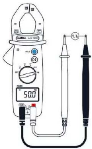
3.9. Check of frequency in voltage mode24
3.10. Check of frequency in current mode24
3.11. Zero mode/"Delta" function ..... 25
3.12. Storage 25
3.13. "Peak" function 25
3.14. Auto-shutdown 25
4. TECHNICAL SPECIFICATIONS ..... 25
4.1. Reference conditions ..... 25
4.2. Specifications 25
4.2.1. DC voltage 25
4.2.2. AC voltage 26
4.2.3. DC current 26
4.2.4. AC current 26
4.2.5. Resistance 26
4.2.6. Continuity 26
4.2.7. Frequency (for current) 26
4.2.8. Frequency (for voltage) 27
5. GENERAL SPECIFICATIONS ...... 27
5.1. Digital display 27
5.2. TRMS measures 27
5.3. Environmental conditions ..... 27
5.4. Power supply 27
5.5. Mechanical features ...... 27
5.6. Compliance with international standards 27
5.7. Safety 27
6. MAINTENANCE 28
6.1. Cleaning 28
7. WARRANTY 28
1. GENERAL INSTRUCTIONS
Thank you for purchasing a MX 350/MX 355. For best results from your current clamp:
- read this user manual carefully,
- comply with the precautions for use.
1.1. Precautions and safety measures
This device is compliant with safety standard IEC 61010-2-032, the leads are compliant with IEC 61010-031 for voltages up to 600 V in category III.
Failure to observe the safety instructions may result in electric shock, fire, explosion, or destruction of the instrument and of the installations.
1.1.1. Symbols

WARNING, DANGER! The operator should refer to this user's manual whenever this danger symbol appears.

Earth.

Equipment protected throughout by double or reinforced insulation.

Application or withdrawal authorized on bare conductors carrying dangerous voltages. Type A current sensor as per IEC 61010-2-032.
The rubbish bin with a line through it indicates that, in the European Union, the product must undergo selective disposal in compliance with Directive WEEE 2002/96/EC. This equipment must not be treated as household waste

The CE marking indicates conformity with European directives, in particular LVD and EMC.

Battery

Alternating current.

Direct current

AC or DC

Important instruction
1.1.2. Definitions of the measurement categories
Measurement category IV corresponds to measurements taken at the source of low-voltage installations.
Example: power feeders, meters and protection devices.
Measurement category III corresponds to measurements on building installations.
Example: distribution panel, circuit-breakers, machines or fixed industrial devices.
Measurement category II corresponds to measurements taken on circuits directly connected to low-voltage installations.
Example: power supply to domestic electrical appliances and portable tools.
2. INSTRUMENT OVERVIEW
2.1. Delivery condition
Check completeness of the delivery against your order.
- Multilingual user manual on paper
- 1 set of measurement leads (one black and one red)
- 2 1.5V AAA or LR3 batteries
- 1 carrying bag
- 1 test certificate
2.2. Functions
The MX 350 and MX 355 are clamp-on multimeters measuring electrical and physical quantities and grouping the following functions:
| Functions | MX350 | MX355 |
| Measuring AC voltage | ● | ● |
| DC voltage measurement | ● | ● |
| Measuring AC current | ● | ● |
| Measuring DC current | ● | |
| Measuring resistance | ● | ● |
| Continuity test with buzzer | ● | ● |
| Measurement of the voltage frequency | ● | |
| Measurement of the current frequency | ● | |
| Zero mode/"Delta" function | ● | |
| “Peak” function | ● | |
| Auto range | ● | ● |
| Auto stop | ● | ● |
| Storage | ● | ● |
| Hazardous voltage warning | ● | ● |
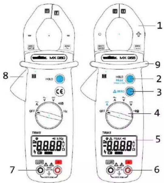
2.3. Device description
text_image
MX 350 HOLD CE OFF Hz TRMS 8 7 1 2 3 4 5 6 HOLD PEAK ZERO OFF +Ω TRMS 9 10 11 12 13 14 15 16 17 18 19 20 21 22 23 24 25 26 27 28 29 30 31 32 33 34 35 36 37 38 39 40| 1 | Jaws |
| 2 | HOLD/Peak function |
| 3 | Δ zerc function (only MX 355) |
| 4 | Switch |
| 5 | Display |
| 6 | Input terminal + |
| 7 | Common terminal |
| 8 | Trigger |
| 9 | Guard |
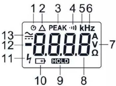
2.4. Display
text_image
1 2 3 4 5 6 13 ≈ 0.8.8.8 kHz 12 -8.8.8 A 11 h HOLD Ω 7 10 9 8| 1 | Auto stop activated |
| 2 | zero function (only MX 355) |
| 3 | Peak function (only MX 355) |
| 4 | Continuity mode |
| 5 | K decimal prefix (only MX 350) |
| 6 | Hz (frequency) (only MX 35C) |
| 7 | A, V or (Ampère, Volt or Ohm) |
| 8 | Digital display |
| 9 | HOLD function. The value is frozen. |
| 10 | Low battery |
| 11 | Presence of hazardous voltage |
| 12 | Negative value |
| 13 | DC or AC mode |
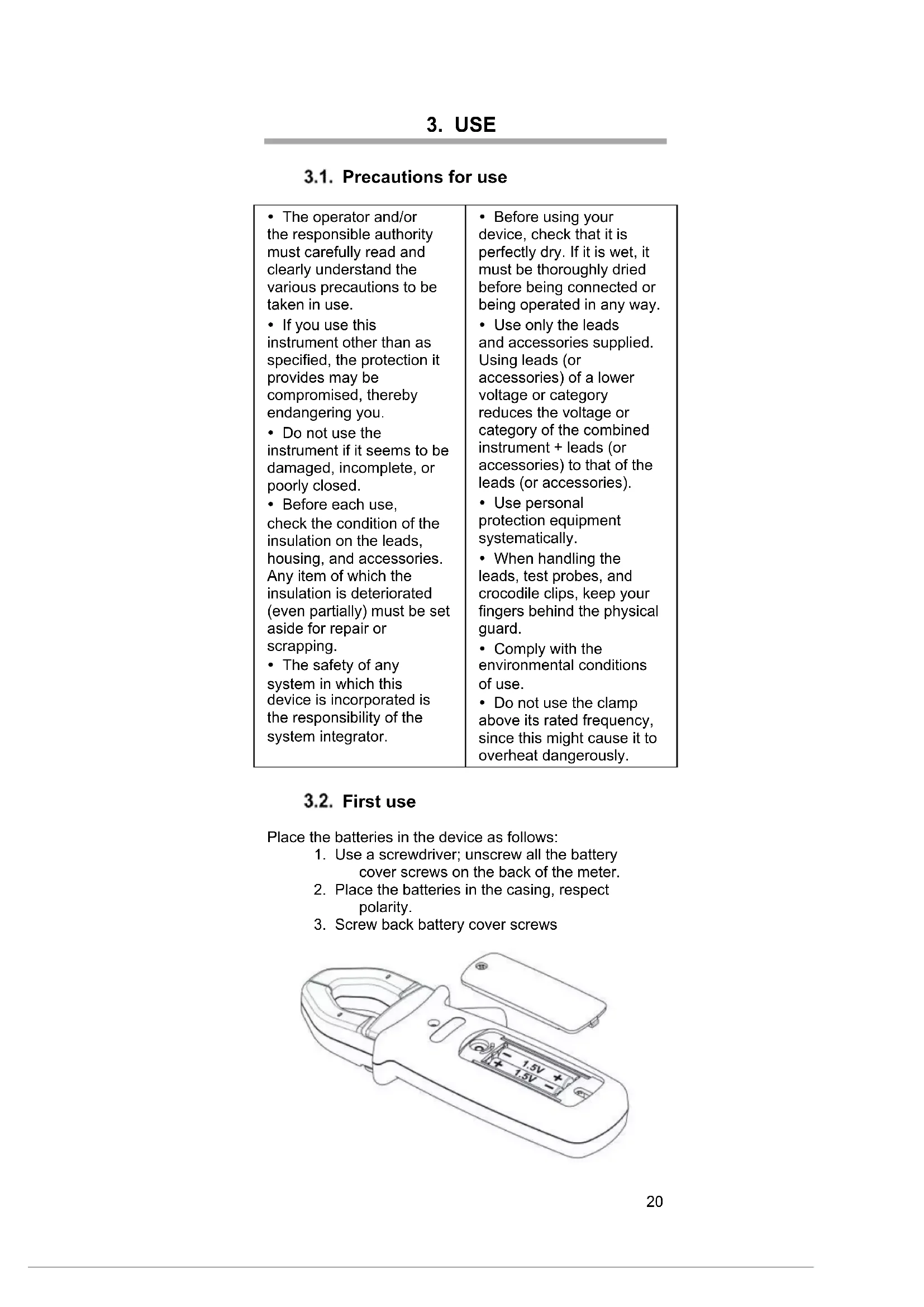
3.1. Precautions for use
• The operator and/or the responsible authority must carefully read and clearly understand the various precautions to be taken in use.
• If you use this instrument other than as specified, the protection it provides may be compromised, thereby endangering you.
- Do not use the instrument if it seems to be damaged, incomplete, or poorly closed.
- Before each use, check the condition of the insulation on the leads, housing, and accessories. Any item of which the insulation is deteriorated (even partially) must be set aside for repair or scrapping.
• The safety of any system in which this device is incorporated is the responsibility of the system integrator.
- Before using your device, check that it is perfectly dry. If it is wet, it must be thoroughly dried before being connected or being operated in any way.
- Use only the leads and accessories supplied. Using leads (or accessories) of a lower voltage or category reduces the voltage or category of the combined instrument + leads (or accessories) to that of the leads (or accessories).
• Use personal protection equipment systematically.
- When handling the leads, test probes, and crocodile clips, keep your fingers behind the physical guard.
• Comply with the environmental conditions of use.
- Do not use the clamp above its rated frequency, since this might cause it to overheat dangerously.
3.2. First use
Place the batteries in the device as follows:
-
Use a screwdriver; unscrew all the battery cover screws on the back of the meter.
-
Place the batteries in the casing, respect polarity.
-
Screw back battery cover screws

natural_image
Line drawing of a handheld remote control device with battery and switch (no text or symbols)
Before changing the batteries, set the switch to "OFF", disconnect the measuring leads and remove the clamp from the circuit measured.
- Start the clamp-on multimeter; make sure that all segments are displayed.
- Check that on Continuity position, and without any input the meter display OL.
• Take out both cords and short circuit, the beeper should sound. - Turn the rotary switch on V and check a known voltage (for example a battery) and make sure voltage is correct.
When all the steps above are correct, you can start to use the meter.
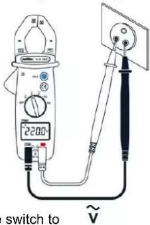
3.3. Measuring AC voltage
text_image
2200 switch to ~V- Set the switch to
- Connect the red test lead to the input terminal and the black test lead to the COM input terminal.
- Apply the probe tips on the points where the AC voltage is to be measured.
- Read the result on the display unit

In the presence of a hazardous voltage (>30V AC) the 12 signal blinks on the screen.
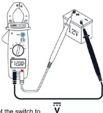
3.4. Measuring DC voltage
text_image
1200 12V at the switch to-
Set the switch to
-
Connect the red test lead to the input terminal and the black test lead to the input terminal.
- Apply the probe tips on the points where the DC voltage is to be measured.
- Read the result on the display unit

In the presence of a hazardous voltage (>30V DC) the signal blinks on the screen.
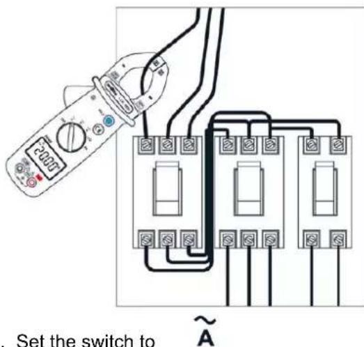
3.5. Measuring AC current
text_image
Set the switch to ~A- Set the switch to
- Open the clamp by pressing the trigger.
- Place the clamp around the conductor to be measured and release the trigger; check that the clamp is correctly closed.
- Read the measurement result on the display unit.

For safety reasons, disconnect the measuring leads before performing this operation. The clamp must be positioned around a single conductor in a circuit, with the risk of rendering the measurement incorrect. The best measurement is obtained with the conductor centred in the middle of the jaws.
3.6. Measuring DC current
(only MX 355)
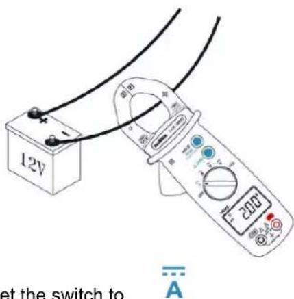
text_image
12V at the switch to A-
Set the switch to
-
Open the clamp by pressing the trigger.
- Place the clamp around the conductor to be measured and release the trigger; check that the clamp is correctly closed.
- Read the measurement result on the display unit.

For safety reasons, disconnect the measuring leads before performing this operation. The clamp must be positioned around a single conductor in a circuit, with the risk of rendering the measurement incorrect. The best measurement is obtained with the conductor centred in the middle of the jaws.
3.7. Measuring resistance
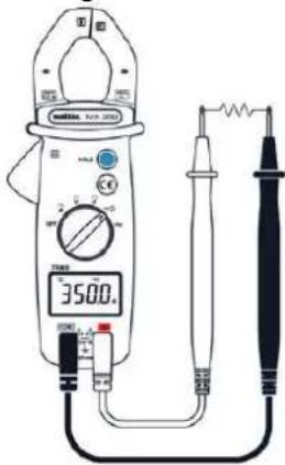
text_image
3500.0 1 2 3 4 5 6 7 8 9 10 11 12 13 14 15 16 17 18 19 20 21 22 23 24 25 26 27 28 29 30 31 32 33 34 35 36 37 38 39 40 41 42 43 44 45 46 47 48 49 50 51 52 53 54 55 56 57 58 59 60 61 62 63 64 65 66 67 68 69 70 71 72 73 74 75 76 77 78 79 80- Set the switch to

- Connect the red test lead to the input terminal and the black test lead to the COM input terminal.
- Apply the probe tips on the points where the resistance is to be measured.
- Read the result on the display unit
3.8. Continuity test with buzzer
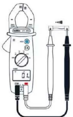
text_image
Diagram of a digital multimeter with labeled components including power supply, analog meters, and probe connections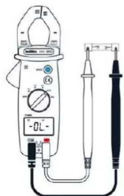
text_image
Diagram of a digital clamp meter with labeled components and measurement scale- Set the switch to

-
Connect the red test lead to the input terminal and the black test lead to the COM input terminal.
-
Apply the probe tips on the circuit to be tested.
-
If the resistance is less than 40 Ω, the buzzer sounds continuously.
3.9. Check of frequency in voltage mode
(only MX 350)
text_image
500Ω U/L DC DC DC DC DC DC DC DC DC DC DC DC DC DC DC DC DC DC DC DC DC DC DC DC DC DC DC DC DC DC DC DC DC DC DC DC DC DC DC DC DC DC DC DC DC DC DC DC DC DC DLC DLC DLC DLC DLC DLC DLC DLC DLC DLC DLC DLC DLC DLC DLC DLC DLC DLC DLC DLC DLC DLC DLC DLC DLC DLC DLC DLC DLC DLC DLC DLC DLC DLC- Set the switch to
- Connect the red measurement lead to the
- input terminal and the black measurement lead to the GCM output terminal.
- Apply the probe tips on the points at which the frequency is to be measured.
- Read the result on the display unit.

3.10. Check of frequency in current mode
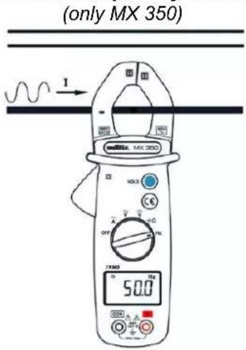
text_image
(only MX 350) I 50.0- Set the switch to
- Place the clamp around the conductor to be measured and release the trigger; check that the clamp is correctly closed.
- Read the result on the display unit.


The simultaneous use of the input terminals and of the jaws of the clamp throws off the frequency reading.
3.11. Zero mode/"Delta" function
(only MX 355)
While the 4 button is pressed, the symbol is displayed. The last value measured becomes the reference value that will be subtracted from subsequent measurements. Press the 4 button again to exit from the mode.
3.12. Storage
Pressing the button freezes the value displayed. To deactivate this function, press the button again.
The "peak" function is used for measuring 1 ms peak value in voltage or current. A long press (2 seconds) on the button activates the "peak" function. A second long press deactivates the function.
3.14. Autoshutdown
The clamp switches off automatically after 20 minutes if no operation is performed. After Autoshutdown, it can be turned on by switching to any range, or pressing the HOLD button. It is possible to deactivate this function by holding down the HOLD button before powering up the clamp.
4. TECHNICAL SPECIFICATIONS
4.1. Reference conditions
Temperature + 23 °C ± 5 °C.
Freq. For AC signal 45-65 Hz
Pure AC signal
Electric field < 40 V/m
Magnetic field <1 V/m
4.2. Specifications

An overshoot of the range is indicated by UL on the display unit and by an audible signal.
4.2.1. DC voltage
| Display rang | Range | Resolutic | Accurac |
| 60 V | 0.05–60.00 \ | 0.01 \ | 1%R + 3 ct |
| 600 \ | 60.0–600.0 \ | 0.1 \ |
4.2.2. AC voltage
| Display rang | Range | Frequenc | Resc | Accuracy |
| 60 V 0.05 | -60.00 V | 48-65 H; | 0.01 V | 1.9%R + 5 |
| 65-400 H. | 3.8%R + 5 | |||
| 600 V 60.0 | -600.0 V | 48-65 H; | 0.1 V | 1.9%R + 5 |
| 65-400 H. | 3.8%R + 5 |
Note : The display indicates "OL" above 630V (900V in peak mode - ONLY MX 355). Above 630V RMS, a repetitive beep indicates that the voltage being measured is greater than the safety voltage for which the device is guaranteed. The display indicates "OL".
4.2.3. DC current
(only MX 355)
| Display rang | Range | Resolutio | Accuracy |
| 60 A | 0.1C - 60.00 A | 0.01 | 2.5%R + 10 ct |
| 400 | 60.C - 400.0 | 0.1 |
4.2.4. AC current
MX 350
| Display range | Range | Frequenc | Resc | Accurac |
| 60 A | 0.05–60.00 / | 48–65 Hz | 0.01 / | 1.9%R + 5 |
| 65–400 Hz | 3.8%R + 5 | |||
| 400 / | 60.0–400.0 / | 48–65 Hz | 0.1A | 1.9%R + 5 |
| 65–400 Hz | 3.8%R + 5 |
MX 355
| Display range | Range | Frequenc | Resc | Accurac |
| 60 A | 0.05–60.00 A | 48–65 Hz | 0.01 A | 1.9%R + 5 |
| 65–400 H: | 3.8%R + 5 | |||
| 400 A | 60.0–400.0 A | 48–65 Hz | 0.1A | 1.9%R + 5 |
| 65–400 H: | 3.8%R + 5 |
Note: The display indicates "OL" above 420A (600A in peak mode – ONLY MX 355). Above 420A RMS, a repetitive beep indicates that the current being measured is greater than the safety current for which the device is guaranteed. The display indicates "OL".
4.2.5. Resistance
| Display range | Range | Resolution | Accuracy |
| 600 Ω | 0.2 – 600.0 Ω | 0.1 Ω | 1%R+ 2ct |
4.2.6. Continuity
Detection threshold
≤ 35 Ω typical
4.2.7. Frequency (for current)
(only MX 350)
| Displa range | Range Resol Accuracy Sensibility | |||
| 600 H: | 20.(-600.0 H) | 0.1 H | 0.2%R + 2 ct | 3 Arms |
| 6 kHz: | 0.60(-6.000 kHz) | 0.00 kHz | ||
| 10 kHz: | 6 - 10 kHz | 0.0 kHz | 0.2%R + 2 | 3 Arm |
4.2.8. Frequency (for voltage) (only MX 350)
| Display range | Range | Resc | Accurac | Sensibili |
| 600 H: | 10.0–600.0 H | 0.1 H | 0.1%R + 2ct | 5 Vrms |
| 6 kHz: | 0.60 –6.000 kHz | 0.001 kHz | ||
| 60 kHz: | 6.0C–60.00 kHz | 0.01 Hz | 0.1%R + 2ct | 5 Vrms |
| 100 kHz | 60.C–100.0 kHz | 0.1 kHz | 0.1%R + 2ct | 5 Vrms |
5. GENERAL SPECIFICATIONS
5.1. Digital display
Display LCD 6000 counts
5.2. TRMS measures
Sampling 2 measurements per second Accuracy True RMS value measured up to 1kHz (-3dB), pass band ≤3.5kHz
Peak factor ≥1.5 full scale
5.3. Environmental conditions
Operation temperature 0°C à +40°C Storage temperature -10°C à +60°C Relative humidity < 70% RH
5.4. Power supply
Battery 2 x 1.5 V AAA or LR03 Battery life MX 350: about 200 hours MX 355: about 40 hours
5.5. Mechanical features
Dimensions 199 x 75 x 36 mm Jaws opening MX 350 26 mm MX 355 30 mm Weight 243 g (avec piles) Protection rating IP30
5.6. Compliance standards with international
Safety IEC 61010-1; IEC 61010-2-032 IEC 61010-2-033; IEC 61010-031 EMC IEC 61326-1
5.7. Safety
Insulation double insulation - class II Degree of pollution 2 Altitude < 2000 m Category CAT III 600 V
6. MAINTENANCE

Except for the batteries, the instrument contains no parts that can be replaced by personnel who have not been specially trained and accredited. Any unauthorized repair or replacement of a part by an "equivalent" may gravely impair safety.
6.1. Cleaning
Disconnect the instrument completely and turn the rotary switch to OFF. Use a soft cloth, dampened with soapy water. Rinse with a damp cloth and dry rapidly with a dry cloth or forced air. Do not use alcohol, solvents, or hydrocarbons. Keep the clamp jaws as clean as possible.
7. WARRANTY
Except as otherwise stated, our warranty is valid for 24 months starting from the date on which the equipment was sold. Extract from our General Conditions of Sale provided on request.
The warranty does not apply in the following cases:
- Inappropriate use of the equipment or use with incompatible equipment;
- Modifications made to the equipment without the explicit permission of the manufacturer's technical staff;
- Work done on the device by a person not approved by the manufacturer;
- Adaptation to a particular application not anticipated in the definition of the equipment or not indicated in the user's manual;
- Damage caused by shocks, falls, or floods.
natural_image
Line drawing of a handheld electronic device with battery and switch components (no text or symbols)
text_image
Diagram of a digital multimeter connected to a power supply with labeled components and a digital display showing 2200Ω.text_image
Diagram showing a multimeter connected to three electrical components with labeled terminals and wiring connections
text_image
Diagram showing two types of analog multimeters with labeled probes and a digital display, likely for measurement or testing purposes.natural_image
Line drawing of a remote control device with battery pack and two ports (no text or symbols)
text_image
Diagram of a digital multimeter connected to a power supply with labeled components and measurement scaletext_image
Diagram showing two identical analog multimeters connected via probes, displaying digital and physical measurement setups with labels like 'HOLD', 'OFF', and 'TOMS'.natural_image
Line drawing of a remote control device with battery pack and two ports (no text or symbols)
text_image
Diagram of a digital multimeter connected to a power supply with labeled components and measurement scaletext_image
Diagram showing a multimeter connected to three electrical components with labeled terminals and wiring connections
text_image
VOL 300 HOLE CE OFF 25Ω 1Hz 35.00Ω A A + - 25Ω 25Ω 25Ω 25Ω 25Ω 25Ω 25Ω 25Ω 25Ω 25Ω 25Ω 25Ω 25Ω 25Ω 25Ω 25Ω 25Ω 25Ω 25Ω 25Ω 25Ω 25Ω 25Ω 25Ω 25Ω 25Ωtext_image
Technical line drawing of two analog multimeters with digital displays and probe probes, showing measurement ranges and terminal connections.text_image
I mRNA. MAX 2053 HOLD E OFF 100 1Hz PWM 50.0 2000 A B C D E F G H I J K L M N O P Q R S T U V W X Y Z A B C D E F G H I J K L M N O P Q R S T U V W X Y ZOur international contacts
www.chauvin-arnoux.com/contacts

CHAUVIN ARNOUX
GROUP