Sanpera II - Guitar amp PEAVEY - Free user manual and instructions
Find the device manual for free Sanpera II PEAVEY in PDF.

| Brand | Peavey |
| Model | Sanpera II |
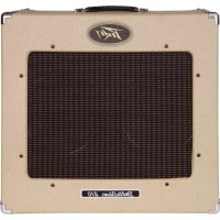
| Product Type | Control pedal for VYPYR amplifier |
| Dimensions (approx.) | 40 x 20 x 6 cm |
| Weight (approx.) | 1.5 kg |
| Power Supply | By the VYPYR amplifier via included 8-pin MIDI cable |
| Main Functions | Expression pedal, bank and preset selection, manual mode, looper, tuner, wah/pitch shift control, tap tempo |
| Display | LCD screen showing bank, preset, active effects |
| Number of Presets | Up to 412 saveable presets (100 banks of 4 + 3 banks A, B, C) |
| Maintenance and Cleaning | Clean with a dry cloth only, do not use liquids or solvents |
| Safety | Do not open the device, risk of electric shock. Any repair should be carried out by a Peavey authorized technician. Do not expose to rain or moisture. Unplug during storms or prolonged non-use. |
| Spare Parts and Repairability | Repair only by a Peavey authorized technician. No user-serviceable parts. |
| General Information | Control pedal designed for Peavey VYPYR amplifiers. Comes with 8-pin MIDI cable. Features two expression pedals (volume/tuner and wah/pitch shift). |
| Looper Capacity | Loop recording and playback, duration not specified |
| Calibration Mode | Allows recalibration of expression pedals and screen contrast |
| Compatibility | Peavey VYPYR amplifiers |
| Number of Buttons | 6 selection buttons (bank up/down, 4 presets/effects) + 2 looper buttons + 1 tap tempo + 1 manual mode |
| Connection Type | 8-pin MIDI cable (included) |
Frequently Asked Questions - Sanpera II PEAVEY
User questions about Sanpera II PEAVEY
0 question about this device. Answer the ones you know or ask your own.
Ask a new question about this device
Download the instructions for your Guitar amp in PDF format for free! Find your manual Sanpera II - PEAVEY and take your electronic device back in hand. On this page are published all the documents necessary for the use of your device. Sanpera II by PEAVEY.
USER MANUAL Sanpera II PEAVEY
Intended to alert the user to the presence of uninsulated "dangerous voltage" within the product's enclosure that may be of sufficient magnitude to constitute a risk of electric shock to persons.
Intended to alert the user of the presence of important operating and maintenance (servicing) instructions in the literature accompanying the product.
CAUTION: Risk of electrical shock — DO NOT OPEN!
CAUTION: To reduce the risk of electric shock, do not remove cover. No user serviceable parts inside. Refer servicing to qualified service personnel.
WARNING: To prevent electrical shock or fire hazard, this apparatus should not be exposed to rain or moisture, and objects filled with liquids, such as vases, should not be placed on this apparatus. Before using this apparatus, read the operating guide for further warnings.
Protective earthing terminal. The apparatus should be connected to a mains socket outlet with a protective earthing connection.


IMPORTANT SAFETY INSTRUCTIONS
WARNING: When using electrical products, basic cautions should always be followed, including the following:
-
Read these instructions.
-
Keep these instructions.
-
Heed all warnings.
-
Follow all instructions.
-
Do not use this apparatus near water.
-
Clean only with a dry cloth.
-
Do not block any of the ventilation openings. Install in accordance with manufacturer's instructions.
-
Do not install near any heat sources such as radiators, heat registers, stoves or other apparatus (including amplifiers) that produce heat.
-
Do not defeat the safety purpose of the polarized or grounding-type plug. A polarized plug has two blades with one wider than the other. A grounding type plug has two blades and a third grounding plug. The wide blade or third prong is provided for your safety. If the provided plug does not fit into your outlet, consult an electrician for replacement of the obsolete outlet.
-
Protect the power cord from being walked on or pinched, particularly at plugs, convenience receptacles, and the point they exit from the apparatus.
-
Only use attachments/accessories provided by the manufacturer.
-
Use only with a cart, stand, tripod, bracket, or table specified by the manufacturer, or sold with the apparatus. When a cart is used, use caution when moving the cart/apparatus combination to avoid injury from tip-over.
-
Unplug this apparatus during lightning storms or when unused for long periods of time.
-
Refer all servicing to qualified service personnel. Servicing is required when the apparatus has been damaged in any way, such as power-supply cord or plug is damaged, liquid has been spilled or objects have fallen into the apparatus, the apparatus has been exposed to rain or moisture, does not operate normally, or has been dropped.
-
Never break off the ground pin. Write for our free booklet "Shock Hazard and Grounding." Connect only to a power supply of the type marked on the unit adjacent to the power supply cord.
-
If this product is to be mounted in an equipment rack, rear support should be provided.
-
Note for UK only: If the colors of the wires in the mains lead of this unit do not correspond with the terminals in your plug, proceed as follows: a) The wire that is colored green and yellow must be connected to the terminal that is marked by the letter E, the earth symbol, colored green or colored green and yellow. b) The wire that is colored blue must be connected to the terminal that is marked with the letter N or the color black. c) The wire that is colored brown must be connected to the terminal that is marked with the letter L or the color red.
-
This electrical apparatus should not be exposed to dripping or splashing and care should be taken not to place objects containing liquids, such as vases, upon the apparatus.
-
The on/off switch in this unit does not break both sides of the primary mains. Hazardous energy can be present inside the chassis when the on/off switch is in the off position. The mains plug or appliance coupler is used as the disconnect device, the disconnect device shall remain readily operable.
-
Exposure to extremely high noise levels may cause a permanent hearing loss. Individuals vary considerably in susceptibility to noise-induced hearing loss, but nearly everyone will lose some hearing if exposed to sufficiently intense noise for a sufficient time. The U.S. Government's Occupational Safety and Health Administration (OSHA) has specified the following permissible noise level exposures:
Duration Per Day In Hours Sound Level dBA, Slow Response
| 8 | 90 | ||
| 6 | 92 | ||
| 4 | 95 | ||
| 3 | 97 | ||
| 2 | 100 | ||
| 112 | 102 | ||
| 1 | 105 | ||
| 1/2 | 110 | ||
| 1/4 or less | 115 |
According to OSHA, any exposure in excess of the above permissible limits could result in some hearing loss. Earplugs or protectors to the ear canals or over the ears must be worn when operating this amplification system in order to prevent a permanent hearing loss, if exposure is in excess of the limits as set forth above. To ensure against potentially dangerous exposure to high sound pressure levels, it is recommended that all persons exposed to equipment capable of producing high sound pressure levels such as this amplification system be protected by hearing protectors while this unit is in operation.
SAVE THESE INSTRUCTIONS!
a) The wire that is colored green and yellow must be connected to the terminal that is marked by the letter E, the earth symbol, colored green or colored green and yellow.
b) The wire that is colored blue must be connected to the terminal that is marked with the letter N or the color black.
c) The wire that is colored brown must be connected to the terminal that is marked with the letter L or the color red.
Logo referenced in Directive 2002/96/EC Annex IV(OJ(L)37/38,13.02.03 and defined in EN 50419: 2005
The bar is the symbol for marking of new waste and is applied only to equipment manufactured after 13 August 2005
Correct Disposal of this product. This marking indicates that this product should not be disposed with other house hold wastes throughout the EU. To prevent possible harm to the environment or human health from uncontrolled waste disposal, recycle it responsibly to promote the sustainable reuse of material resources. To return your used device, please use the return and collection systems, or contact the retailer where the product was purchased. They can take this product for environmental safe recycling.

FCC Compliancy Statement
This device complies with Part 15 of the FCC rules. Operation is subject to the following two conditions: (1) this device may not cause harmful interference, and (2) this device must accept any interference received, that may cause undesired operation.
Warning: Changes or modifications to the equipment not approved by Peavey Electronics Corp. can void the user's authority to use the equipment.
Note - This equipment has been tested and found to comply with the limits for a Class B digital device, pursuant to Part 15 of the FCC Rules. These limits are designed to provide reasonable protection against harmful interference in a residential installation. This equipment generates, uses and can radiate radio frequency energy and, if not installed and used in accordance with the instructions, may cause harmful interference to radio communications. However, there is no guarantee that interference will not occur in a particular installation. If this equipment does cause harmful interference to radio or television reception, which can be determined by turning the equipment off and on, the user is encouraged to try and correct the interference by one or more of the following measures.
- Reorient or relocate the receiving antenna.
- Increase the separation between the equipment and receiver.
- Connect the equipment into an outlet on a circuit different from that to which the receiver is connected.
- Consult the dealer or an experienced radio/TV technician for help.

Peavey Electronics Corporation • 5022 Hartley Peavey Drive • Meridian, MS • 39305
(601) 483-5365 • FAX (601) 486-1278 • www.peavey.com
VYPYR® SANPERA™ II
Welcome
Thank you for purchasing the Sanpera II foot controller for your VYPYR® amplifier. We are certain you will enjoy having the control of your VYPYR at your feet.
Note:
Your Sanpera ^TM II is powered by your VYPYR ^ amplifier and requires the special 8-pin MIDI cable included with your Sanpera in order to function correctly.
VYPYR®
SANPERA™ II

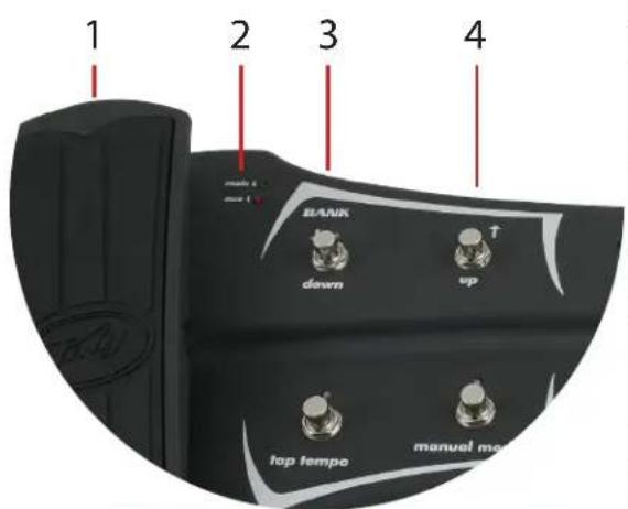
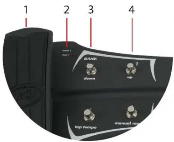
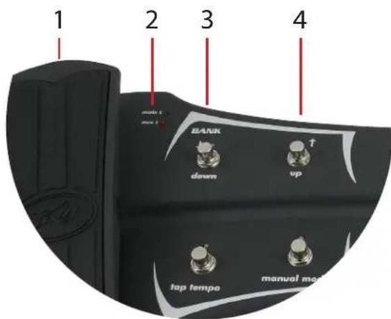
1. Expression Pedal
This pedal controls the overall volume of the amplifier. To enter TUNER MODE, simply depress the toe area of the expression pedal to activate the internal switch. While in TUNER MODE the pedal will continue to control the volume of the amplifier, allowing you to choose whether or not you hear the note you are tuning.
NOTE: You can swap the functionality of the two on board Expression pedals by entering CALIBRATION MODE.
2. Main/AUX Indication LED
These LEDs indicate whether the pedal is in MAIN MODE or AUX MODE. Depress the toe area of the expression pedal to switch between modes.
Left pedal: Volume/Tuner Right pedal: Wah/Pitch Shift
3. Bank Down
This button allows you to scroll downward through a list of BANKS that contain four PRESETS each. The button also serves to help scroll through characters while naming PRESETS.
4. Bank Up
Same as item 3, only it scrolls in the opposite direction.
TIP: You can hold down the Bank Up and Bank Down buttons to scroll quickly.
VYPYR® SANPERA™ II
5. Display Screen
The display screen indicates not only which patch and amp model is currently selected, it also indicates which effects are active, and which effects are on standby ready to be activated.

A. Bank and Preset Indication
The presets are stored in banks of four. Banks A, B, and C 1-4 correspond with the preset buttons on the front of your VYPYR® amplifier. There are an additional 100 banks of 4 allowing you to explore and store up to 412 unique presets in your VYPYR amplifier.
B. Preset Name
This displays the name of the preset selected on your VYPYR amplifier. To change the name simply press and hold any one of the four preset select buttons (items 12-5) while in PRESET MODE. Use buttons 3 and 4 to scroll through characters and buttons 6 and 7 to advance or move the cursor backward through the preset name. To store a preset, select the desired bank using buttons 3 and 4 while the cursor is positioned under item A. After you are finished selecting the bank and desired name, press any one of the preset buttons (items 12-15) to store the new preset in that location. You can also abort the store by pressing the Tap Tempo button (item 10).
C. Stompbox Indicator
This displays the stompbox selected on the Stompbox encoder on the VYPYR amplifier. If the item appears in CAPS the effect is ON; if it appears in lower case text, the effect is off. The effect can be turned on and off without changing presets (see MANUAL MODE).
D. Amp Indicator
This displays the amplifier selected on the Amplifier encoder on the VYPYR® amplifier.
E. Effect Indicator
This displays the effect selected on the Effect encoder on the VYPYR amplifier. If the item appears in CAPS the effect is ON; if it appears in lower case text the effect is off. The effect can be turned on and off without changing presets (see MANUAL MODE).
F. Delay Indicator
This displays indicates the status of the delay effect. When “DL” is in CAPS the effect is ON; when “dl” is in lower case text the effect is off. The effect can be turned on and off without changing presets (see MANUAL MODE).
G. Reverb Indicator
This displays indicates the status of the reverb effect. When “RV” is in CAPS the effect is ON; when “rv” is in lower case text the effect is off. The effect can be turned on and off without changing presets (see MANUAL MODE).
VYPYR®
SANPERA™ II

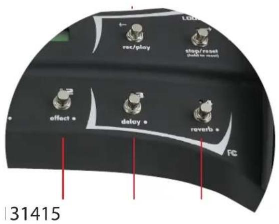
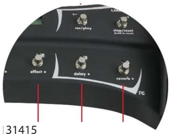
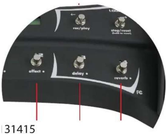
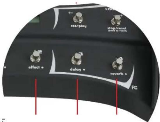
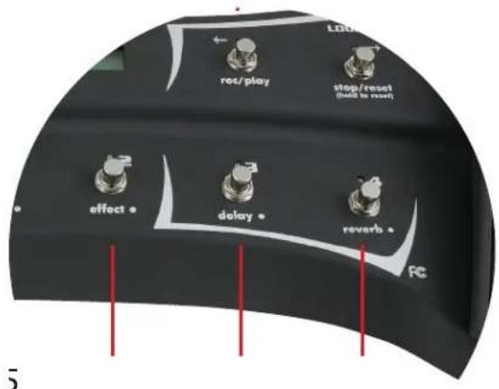
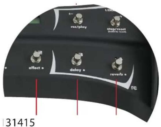
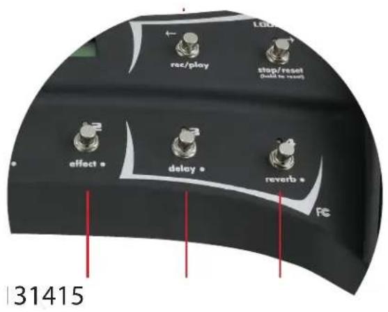
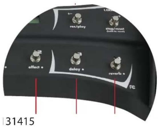
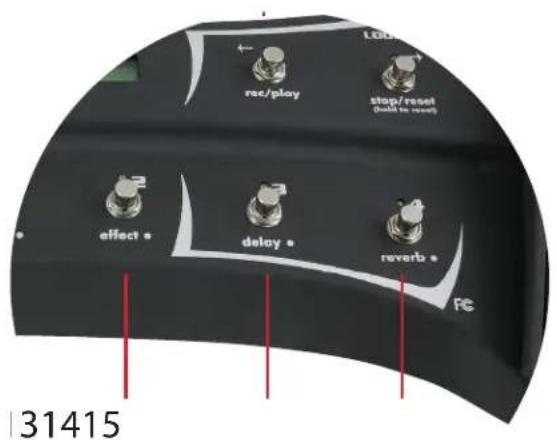
LOOPER CONTROLS
6. Rec/Play
You will spend hours with this! To record a loop for playback simply start playing, when you want to START the loop, press this button and the amp will begin recording the loop. When you want to STOP recording, press this button again and the looper will stop recording and automatically begin to play back.
7. Stop/Reset
To STOP a loop in process, press this button. To ERASE the currently stored loop (recorded by pressing button 6), press and hold this button for 3 seconds.
8. Main/AUX Indication LED
These LEDs indicate whether the pedals is in MAIN MODE or AUX MODE. Depress the toe area of the expression pedal to switch between modes. Out of the box Main indicates Wah, Aux indicates Pitch Shift.
9. Expression Pedal
When active, this pedal controls a universal wah. To activate the wah depress the toe area of the footswitch. When Pitch Shift is selected on the amplifier, this pedal will control the pitch of the signal.
10. Tap Tempo
Tap this button to set the tempo of the delay. If you don't hear the delay effect chances are its not turned ON in the preset. The LED above the button indicates the current delay tempo.
TIP: You can change amp presets after you have recorded your loop, allowing you to play a totally different sound over top of the loop!
VYPYR® SANPERA™ II

11. Manual Mode
Pressing this button allows you to be able to turn on and off individual effects using buttons 12-15. Essentially this control allows you to select between the ability to access the four PRESETS that are in the selected BANK, or turn on and off individual effects. When the LEDs above this button AND above buttons 12-15 are red, you are in PRESET MODE. PRESET MODE allows you to select between the three presets in the selected bank, indicated by the three numbers (1-3) ABOVE buttons 12-15. NOTE: The first generation Vypyr amplifiers had the presets arranged in 3 banks of 4 presets each. The Sanpera II still includes button 15 for customers using Vypyr series 1. For the Vypyr VIP series and when in PRESET MODE, button 15 will be inoperatibl.When the LEDs above button 11 AND buttons 12-15 are GREEN you are in MANUAL MODE and can manually turn on and off individual effects indicated by the labels BELOW buttons 12-15.
12. Preset 1/Stompbox
In PRESET MODE, this button will select the preset stored in location
1 of the selected bank (item 5). In MANUAL MODE this button will turn ON/OFF the Stompbox selected on the amplifier. When the LED is OFF the effect is also OFF.
13. Preset 2/Effect
In PRESET MODE, this button will select the preset stored in location 2 of the selected bank (item 5). In MANUAL MODE this button will turn ON/OFF the effect selected on the amplifier. When the LED is OFF the effect is also OFF. NOTE: The Vypyr VIP I does not have an effects encoder, therefore in MANUAL MODE this button will be inoperative.
14. Preset 3/Delay
In PRESET MODE this button will select the preset stored in location 3 of the selected bank (item 5). In MANUAL MODE this button will turn ON/OFF the Delay function selected on the amplifier. When the LED is OFF the delay is also OFF.
15. Preset 4/Reverb
In PRESET MODE, this button will select the preset stored in location 4 of the selected bank (item 5). If using the first generation Vypyr amplifiers. If using a Vypyr VIP amplifier, this button will be inoperative when in PRESET MODE. In MANUAL MODE, this button will turn ON/OFF the Reverb selected on the amplifier. When the LED is OFF the reverb is also OFF. NOTE: The new Vypyr VIP series has the presets arranged in sets of 3. Because of this, when using the new Sanpera foot controller with the Vypyr VIP series, in PRESET MODE this button will be inoperative.
CALIBRATION MODE:
Occasionally it may be necessary to re-calibrate your expression pedals, or the LCD contrast. To enter calibration mode, press and hold button 15. While holding button 15, momentarily press button 12 to activate CALIBRATION MODE, then simply follow the on-screen instructions. After calibration, turn the VYPYR ^® off and back on to use the new settings.
TIP: If you'd like to swap the location of the expression pedals, just enter calibration mode and follow the on-screen instructions!
VYPYR®
SANPERA™ II
Bienvenido

VYPYR®
SANPERA™ II
CONTROLES LOOPER
MODO CALIBRACIÓN:

C. Indication Stompbox
VYPYR®
SANPERA™ II
CONTROLES DE LOOPER 6. Enr/Lect
MODE CALIBRATION
Links Pedal: Lautstärke/Tuner Rechtes Pedal: Wah/Pitch-Shift
3. Bank nach unten
VYPYR®
SANPERA™ II
LOOPER -Steuerung
6. Rec / Play
KALIBRIERUNGSMODUS:
VYPYR® SANPERA™ II
LOOPER-SILMUKKAOH-JAIMET
6. Rec / Play
KALIBROINTITILA:
VYPYR®
SANPERA™ II
LOOPER-KONTROLLER

KALIBRERINGSLÄGE

A. Bank en Preset Indicatie
C. Stompbox Indicator
VYPYR®
SANPERA™ II
LOOPER BEDIENINGEN
6. Opname/Spelen
KALIBRATIEMODUS:

VYPYR® SANPERA™ II
CONTROLES DE LOOPER
6. Gravar/Executar (Rec / Play)
MODO DE CALIBRAÇÃO:
A. バンクリプリセット表示
VYPYR®
SANPERA™ II
LOOPER制御部
6. 録音/再生
カリプレーションモード:

A. 音库和预置指示
VYPYR® SANPERA™ II
LOOPER 控制
6. 录音/播放
校对模式:

A. 뱙크 및 프리셋 표시
VYPYR® SANPERA™ II
LOOPER 제어
6. 레코딩/재생
CALIBRATION MODE:
natural_image
Abstract black-and-white geometric logo design with stylized arrow-like shapes (no text or symbols)www.peavey.com
Warranty registration and information for U.S. customers available online at
www.peavey.com/warranty
or use the QR tag below

Features and specifications subject to change without notice.
Peavey Electronics Corporation
5022 Hartley Peavey Drive
Meridian, MS 39305
(601) 483-5365
FAX (601) 486-1278

Logo referenced in Directive 2002/96/EC Annex IV
(OJ(L)37/38,13.02.03 and defined in EN 50419: 2005
The bar is the symbol for marking of new waste and
is applied only to equipment manufactured after
13 August 2005