
Delta Blues 210 - Guitar amp PEAVEY - Free user manual and instructions
Find the device manual for free Delta Blues 210 PEAVEY in PDF.
| Product type | Amplifier for electric guitar |
| Brand | Peavey |
| Model | Delta Blues 210 |
| Category | Guitar amplifier |
| Technology | All-tube |
| Preamp tubes | 3 x 12AX7 |
| Power tubes | 4 x EL84 |
| Output power | 30 W RMS (at 16 ohms) |
| Speakers | 2 x 10" high-quality |
| Number of channels | 2 (Clean and Lead) |
| Controls per channel | Normal: Volume; Lead: Pre gain, Post gain, Boost |
| Equalization | Passive 3-band (Bass, Middle, Treble) |
| Reverb | Spring reverb with level control |
| Tremolo | Tube-based with Speed and Intensity controls |
| Effects loop | Yes (Send and Return) |
| Optional footswitches | Channel/Boost switch (03054360 or 03330850), Reverb ON/OFF (03051000) |
| External speaker output | Yes, minimum 16 ohms impedance |
| Power supply | 120 V~, 60 Hz, 75 W |
| Standby consumption | 0.04 kWh |
| Operating consumption | 0.075 kWh |
| Fuse | F3A (250 V) |
| Dimensions (approx.) | 60 x 50 x 30 cm (estimated) |
| Weight (approx.) | 20 kg (estimated) |
| Covering | Classic tweed |
| Chassis | Chrome-plated |
| Care and cleaning | Unplug before cleaning; use a dry cloth; do not use solvents |
| Safety | Do not expose to moisture; do not block vents; replace fuse with identical type |
Frequently Asked Questions - Delta Blues 210 PEAVEY
User questions about Delta Blues 210 PEAVEY
0 question about this device. Answer the ones you know or ask your own.
Ask a new question about this device
Download the instructions for your Guitar amp in PDF format for free! Find your manual Delta Blues 210 - PEAVEY and take your electronic device back in hand. On this page are published all the documents necessary for the use of your device. Delta Blues 210 by PEAVEY.
USER MANUAL Delta Blues 210 PEAVEY
natural_image
Front view of a vintage portable guitar with a logo on the grille, labeled 'Classic. 30' at the bottom (no other text or symbols visible)Operating Manual

FCC/ICES Compliancy Statement
This device complies with Part 15 of the FCC rules and Industry Canada license-exempt RSS Standard(s). Operation is subject to the following two conditions: (1) this device may not cause harmful interference, and (2) this device must accept any interference received, that may cause undesired operation.
Warning: Changes or modifications to the equipment not approved by Peavey Electronics Corp. can void the user's authority to use the equipment.
Note – This equipment has been tested and found to comply with the limits for a Class B digital device, pursuant to Part 15 of the FCC Rules. These limits are designed to provide reasonable protection against harmful interference in a residential installation. This equipment generates, uses, and can radiate radio frequency energy and, if not installed and used in accordance with the instructions, may cause harmful interference to radio communications. However, there is no guarantee that interference will not occur in a particular installation. If this equipment does cause harmful interference to radio or television reception, which can be determined by turning the equipment off and on, the user is encouraged to try and correct the interference by one or more of the following measures.
• Reorient or relocate the receiving antenna.
- Increase the separation between the equipment and receiver.
- Connect the equipment into an outlet on a circuit different from that to which the receiver is connected.
- Consult the dealer or an experienced radio/TV technician for help.
Caution
The equipment complies with FCC radiation exposure limits set forth for an uncontrolled environment.

Peavey Electronics Corporation - 5022 Hartley Peavey Drive - Meridian, MS - 39305 (601) 483-5365 - FAX (601) 486-1278 - www.peavey.com - 80305780 - ©2011
ENGLISH
Classic® 30 / Delta Blues Amplifiers
Ask anyone who has managed to turn a passion into a career, and they can surely pinpoint the exact moment in time that they realized their life's calling. For Hartley Peavey, that moment occurred in 1957 at a Bo Diddley concert deep in Mississippi. The energy he felt and the tones he heard that night would ultimately take form in the first Peavey amplifier. The rest, as we say, is rock & roll history. Today, that original burst of inspiration lives on in one Hartley's of the most enduring creations, the Peavey Classic® Series.
Quite possibly, no amplifier bearing the Peavey name is nearer to Hartley Peavey's heart than the Classic Series. Born where blues and rock & roll began, these amplifiers come alive with vintage vibes, versatility and a timeless design from one of America's enduring musical innovators. The Classic Series is the sound of Delta soul and as close to the source as you'll ever get.
Revered by blues, country, and rock players alike, these true all-tube amps span the tonal landscape from vintage to contemporary with ease. These amps are drenched in the tone that can only come from the combination of three 12AX7 and four EL84 tubes. Add features like 3-band EQ, footswitchable dual channels, Presence control and reverb and you have one of the most versatile amplifiers on the market. So, if only a tube amp will do, check out one of our timeless Classics. Classic looks, classic tone. And they're only from Peavey.
FEATURES:
Four EL84s and three 12AX7s
Premium Speakers
2-channel preamp
Pre- and post-gain controls on lead channels
Normal volume control on clean channel
3-band passive EQ (bass, middle, treble)
Boost switch
Genuine Spring Reverb with level control
Effects loop
Footswitch selectable channel switching, reverb and boost (plus the Tremolo on the Delta Blues)
External speaker capability
Chrome-plated chassis
Tube driven tremolo on Delta Blues
Footswitches optional

VENTILATION: For proper ventilation, allow 24" clearance from the nearest combustible surface.
All vents should have a minimum of 2" of free air space so air can flow thru the unit freely for proper cooling.
flowchart
graph LR
    INPUT["INPUT"] --> NORMAL["NORMAL CHANNEL"]
    NORMAL --> PRE["PRE 5 6 7 8 9 12"]
    PRE --> POST["POST 5 6 7 8 9 12"]
    POST --> REVERB["REVERB 5 6 7 8 9 12"]
    REVERB --> BASS["BASS 5 6 7 8 9 12"]
    BASS --> MIDDLE["MIDDLE 5 6 7 8 9 12"]
    MIDDLE --> TREBLE["TREBLE 5 6 7 8 9 12"]
    TREBLE --> EFX_RET["EFX. RET."]
    EFX_RET --> STANDBY["STANDBY ON POWER ON"]
    STANDBY --> PILOT["PILOT ON"]
    PILOT --> POWER["POWER ON"]
    POWER --> 231489["231489"]
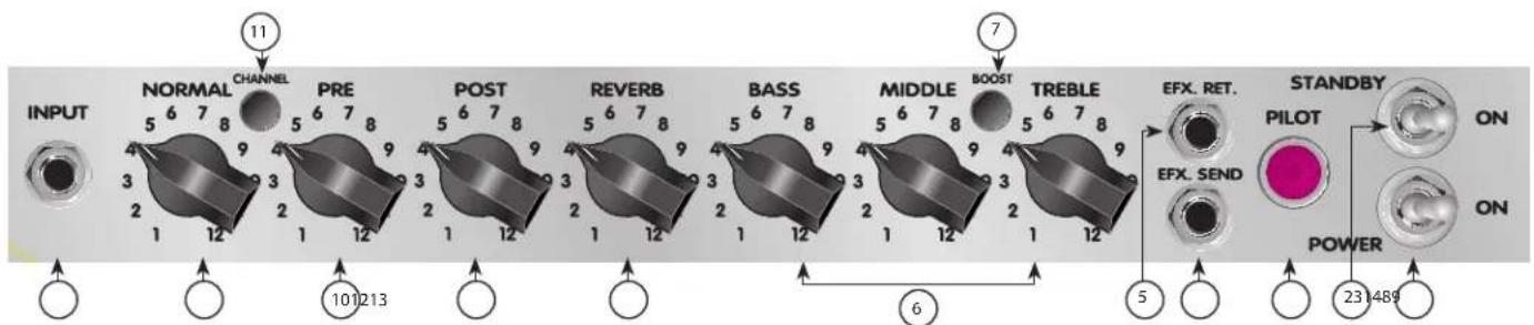
POWER SWITCH
Switch to "ON" position to activate.
STANDBY SWITCH
Allows amp to be placed in standby or active mode. In standby mode the tubes remain hot, but the amplifier is not operational.
PILOT LIGHT LED
Illuminates when AC power is being supplied to the unit.
EFFECTS SEND
Output for supplying signal to external effects or signal processing equipment.
EFFECTS RETURN
Input for returning signals from external effects or signal processing equipment.
TREBLE, MIDDLE, AND BASS EQ
Passive tone controls that regulate high, mid, and low frequencies, respectively.
BOOST SWITCH
Boosts the overall system gain. Depress to the "in" position to activate.
REVERB
Reverberation is an echo effect. Rotate clockwise to increase the effect. Remote footswitch can control ON/OFF.
POST GAIN
Controls the overall volume level of the Lead channel. The final level adjustment should be made after the desired sound has been achieved.
PRE GAIN
Controls the input volume level of the Lead channel.
CHANNEL SELECT SWITCH
Allows selection of the Lead or Normal channel.
NOTE: Channel selection may also be achieved by the remote footswitch. If remote selection is desired, the channel switch must be in the "in" (Lead) position.
NORMAL GAIN
Controls the volume level of the Normal channel.
INPUT
The input jack will accept signals from all types of guitar pickups. Be sure to use a high-quality shielded cable to connect the guitar to the amplifier.
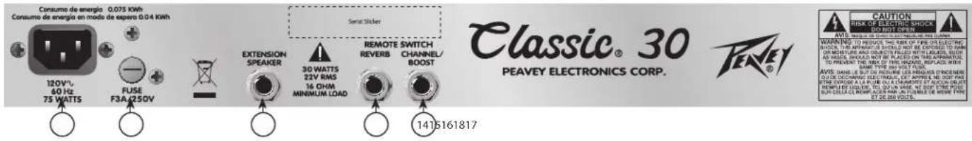
14 REMOTE CHANNEL/BOOST SWITCH JACK
This is provided for the connection of the optional remote footswitch. The footswitch is used to select the Lead or Normal channels and activate the boost. When using the remote footswitch, always insert the plug fully (second click) to ensure proper operation. (requires Peavey footswitch 03054360)
15 REVERB SWITCH JACK
This is provided for the connection of the optional remote footswitch. The footswitch is used to defeat reverb. (requires Peavey footswitch 03051000)
16 EXTERNAL SPEAKER JACK
This is provided for connection of an external speaker cabinet. Minimum total impedance is 8 ohms.
Caution: The on/off switch in this unit does not break both sides of the primary mains. Hazardous energy can be present inside the chassis even when the on/off switch is in the OFF position.
17 FUSE
The fuse is located within the cap of the fuseholder. If the fuse should fail, IT MUST BE REPLACED WITH THE SAME TYPE AND VALUE IN ORDER TO AVOID DAMAGE TO THE EQUIPMENT AND TO PREVENT VOIDING THE WARRANTY. If the amp repeatedly blows fuses, it should be taken to a qualified service center for repair.

WARNING: THE FUSE SHOULD ONLY BE REPLACED WHEN THE POWER CORD HAS BEEN DISCONNECTED FROM ITS POWER SOURCE.

AC POWER INLET:
This is the receptacle for an IEC line cord, which provides AC power to the unit. Connect the line cord to this connector to provide power to the unit. Damage to the equipment may result if improper line voltage is used. (See line voltage marking on unit).

Never break off the ground pin on any equipment. It is provided for your safety. If the outlet used does not have a ground pin, a suitable grounding adapter should be used, and the third wire should be grounded properly. To prevent the risk of shock or fire hazard, always make sure that the amplifier and all associated equipment is properly grounded.
NOTE: FOR UK ONLY
As the colors of the wires in the mains lead of this apparatus may not correspond with the colored markings identifying the terminals in your plug, proceed as follows: (1) The wire that is colored green and yellow must be connected to the terminal that is marked by the letter E, or by the Earth symbol, or colored green or green and yellow. (2) The wire that is colored blue must be connected to the terminal that is marked with the letter N, or the color black. (3) The wire that is colored brown must be connected to the terminal that is marked with the letter L, or the color red.
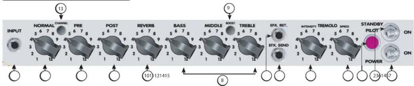
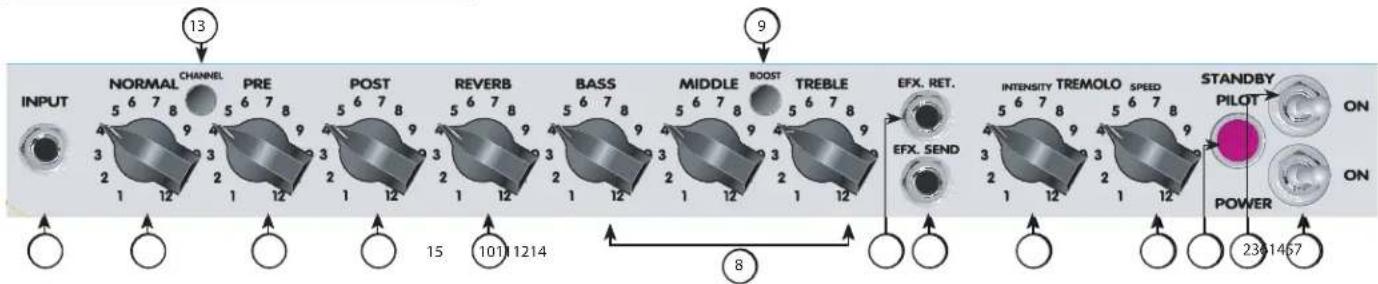
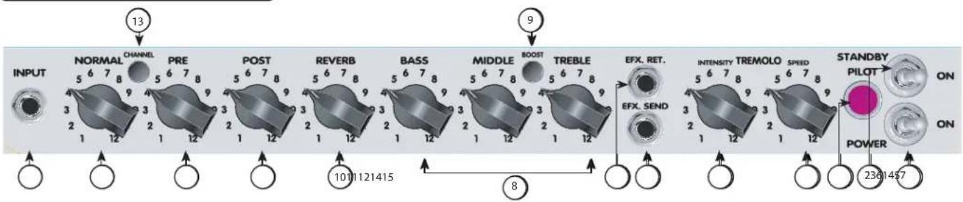
Delta Blues® Control Panel
flowchart
graph LR
    INPUT["INPUT"] --> NORMAL["NORMAL CHANNEL"]
    NORMAL --> PRE["PRE 5 6 7 8 9 3 2 1 12"]
    PRE --> POST["POST 5 6 7 8 9 3 2 1 12"]
    POST --> REVERB["REVERB 5 6 7 8 9 3 2 1 12"]
    REVERB --> BASS["BASS 5 6 7 8 9 3 2 1 12"]
    BASS --> MIDDLE["MIDDLE BOOST 5 6 7 8 9 3 2 1 12"]
    MIDDLE --> TREBLE["TREBLE 5 6 7 8 9 3 2 1 12"]
    TREBLE --> EFX_RET["EFX. RET."]
    EFX_RET --> INTENSITY["TREMOLO SPEED"]
    INTENSITY --> STANDBY_STANDBY["STANDBY PILOT ON"]
    STANDBY_STANDBY --> POWER["POWER ON"]
    POWER --> POWER_OUT["2361467"]
    EFX_RET --> EFX_SEND["EFX. SEND"]
    EFX_SEND --> Power_OUT
    style NORMAL fill:#f9f,stroke:#333
    style PRE fill:#f9f,stroke:#333
    style POST fill:#f9f,stroke:#333
    style REVERB fill:#f9f,stroke:#333
    style MIDDLE fill:#f9f,stroke:#333
    style TREBLE fill:#f9f,stroke:#333
    style EFX_RET fill:#ccf,stroke:#333
    style INTENSITY fill:#ccf,stroke:#333
    style STANDBY_STANDBY fill:#cfc,stroke:#333
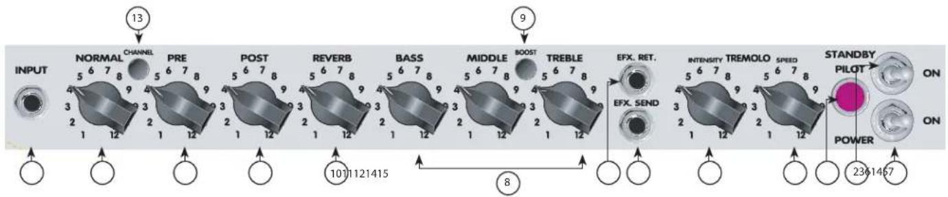
1 POWER SWITCH
Switch to "ON" position to turn on.
STANDBY SWITCH
This two-way switch allows the amp to be placed in the STANDBY mode. In the STANDBY position the tubes stay hot but the amplifier is not operational. Switching to the ON position places the amp in active mode.
PILOT LIGHT
Illuminates when AC power is being supplied to the unit.
TREMOLO SPEED
The speed control determines the rate at which the signal is modulated. This control varies the speed of the Tremolo master oscillator and should provide any speed desired for modern music. Clockwise rotation of the speed control increases the speed of the modulation of the tremolo. The Tremolo feature is defeatable from a remote footswitch.
TREMOLO INTENSITY
The intensity control is used to vary the amount of amplitude modulation of the clean signal. It can be adjusted from barely perceptible to dramatic modulation. Clockwise rotation of the intensity control increases the depth of the tremolo.
EFFECTS RETURN
Input for returning signals to external effects or signal processing equipment.
EFFECTS SEND
Output for supplying signal to external effects or signal processing equipment.
TREBLE, MIDDLE AND BASS EQ
Passive tone controls that regulate high, mid, and low frequencies, respectively.
BOOST SWITCH
Boosts the overall system gain. Depress to the "in" position to activate.
REVERB
Reverberation is an echo effect. Rotate clockwise to increase the effect.
POST GAIN
Controls the overall volume level of the Lead channel. The final level adjustment should be made after the desired sound has been activated.
PRE GAIN
Controls the input volume level of the Lead channel.
CHANNEL SELECT SWITCH
Allows selection of the Lead or Normal channel.
Note: Channel selection may also be achieved by the remote footswitch. If remote selection is desired, the channel switch must be in the "in" (Lead) position.
NORMAL GAIN
Controls the volume level of the Normal channel.
INPUT
The input jack will accept signals from all types of guitar pickups. Be sure to use a high-quality shielded cable to connect the guitar to the amplifier.
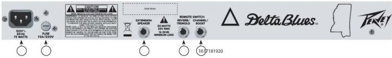
16 REMOTE CHANNEL/BOOST SWITCH JACKS
This is provided for the connection of the optional remote footswitch. The footswitch is used to select the Lead or Normal channels and activate the boost. When using the remote footswitch, always insert the plug fully (second click) to ensure proper operation. (requires Peavey footswitch 03330850)
17 REVERB SWITCH JACK
This is provided for the connection of the optional remote footswitch. The footswitch is used to defeat reverb. (requires Peavey footswitch 03330850)
18 EXTERNAL SPEAKER JACK
This is provided for connection of an external speaker cabinet. Minimum total impedance is 16 ohms.
Caution: The on/off switch in this unit does not break both sides of the primary mains. Hazardous energy can be present inside the chassis even when the on/off switch is in the OFF position.
19 FUSE
The fuse is located within the cap of the fuseholder. If the fuse should fail, IT MUST BE REPLACED WITH THE SAME TYPE AND VALUE IN ORDER TO AVOID DAMAGE TO THE EQUIPMENT AND TO PREVENT VOIDING THE WARRANTY. If the amp repeatedly blows fuses, it should be taken to a qualified service center for repair.
20 AC POWER INLET:
This is the receptacle for an IEC line cord, which provides AC power to the unit. Connect the line cord to this connector to provide power to the unit. Damage to the equipment may result if improper line voltage is used. (See line voltage marking on unit).
Never break off the ground pin on any equipment. It is provided for your safety. If the outlet used does not have a ground pin, a suitable grounding adapter should be used, and the third wire should be grounded properly. To prevent the risk of shock or fire hazard, always make sure that the amplifier and all associated equipment is properly grounded.
NOTE: FOR UK ONLY
As the colors of the wires in the mains lead of this apparatus may not correspond with the colored markings identifying the terminals in your plug, proceed as follows: (1) The wire that is colored green and yellow must be connected to the terminal that is marked by the letter E, or by the Earth symbol, or colored green or green and yellow. (2) The wire that is colored blue must be connected to the terminal that is marked with the letter N, or the color black. (3) The wire that is colored brown must be connected to the terminal that is marked with the letter L, or the color red.


Classic® 30
All-Tube Guitar Amplifier SPECIFICATIONS
POWER AMPLIFIER SECTION
Four 6BQ5/EL84s with 12AX7 driver
Rated Power & Load:
30 W RMS into 16 or 8 ohms
Power @ Clipping (Typically):
(5% THD, 1 kHz, 120 VAC line)
30 W RMS into 16 or 8 ohms
(Bias must be reduced to measure.)
Frequency Response:
+0, -2 dB, 50 Hz to 15 kHz, @ 20 W RMS into
16 ohms
Hum & Noise:
No greater than 80 dB below rated power
Power Consumption:
150 watts, 50/60 Hz, 120 VAC (Domestic)
PREAMP SECTION
Two 12AX7's
The following specs are measured @ 1 kHz with the controls preset as follows:
Pre & Post (lead) @ 0
Reverb Level @ 0
Bass & Treble EQ @ 12
Middle EQ @ 0
Channel Select Out
Boost Switch Out
Nominal level is with Input Gain @ 6
Minimum level is with Input Gain @ 12
Preamp Normal Input:
Impedance: Very high Z, 470 K ohms
Lead Channel (Post Gain @ 12):
Nominal Input Level:
-40 dBV, 10 mV RMS
Minimum Input Level:
-70 dBV, 0.3 mV RMS
Normal Channel (Post Gain @ 12):
Nominal Input Level:
-17 dBV, 140 mV RMS
Minimum Input Level:
-28 dBV, 40 mV RMS
Maximum Input Level:
0 dBV, 1.0 V RMS
Equalization:
(Lead and Normal Channels)
Custom bass, middle, and treble passive-type EQ
Effects Send:
Load Impedance: 1 K ohm or greater
Nominal Output Level: -6 dBV, 0.5 V RMS
Effects Return:
Impedance: High Z, 2 M ohms
Designed Input Level: -6 dBV, 0.5 V RMS
(Switching jack provides Effects Send to Effects
Return connection when not used.)
External Footswitch Function:
Jack 1: Reverb Defeat (when reverb control is raised)
Jack 2: Normal/Lead Channel Select (when Lead activated), Boost on/off
Speaker (Combo Only):
One 12" Speaker 16 ohms
Delta Blues™
All-Tube Guitar Amplifier SPECIFICATIONS
POWER AMPLIFIER SECTION
Four 6BQ5/EL84's with 12AX7 driver
Rated Power & Load:
30 watts RMS into 16 or 8 ohms
Power @ Clipping (Typically):
(5% THD, 1 kHz, 120 V AC line)
30 watts RMS into 16 or 8 ohms
(Bias must be reduced to measure)
Frequency Response:
+0, -2 dB, 50 Hz to 15 kHz,
@ 20 watts RMS into 16 ohms
Hum & Noise:
Greater than 80 dB below rated power
Power Consumption:
150 watts, 50/60 Hz, 120 VAC
(Domestic)
PREAMP SECTION
Two 12AX7's
The following specs are measured
@ 1 kHz with the controls preset as follows:
Pre & Post (lead) @ 0
Reverb Level @ 0
Bass & Treble EQ @ 12
Middle EQ @ 0
Channel Select Out
Boost Switch Out
Nominal level is with Input Gain @ 6.
Minimum level is with Input Gain @ 12.
Preamp Normal Input:
Impedance: Very high Z, 470 K ohms
Lead Channel
(Post Gain @ 12):
Nominal Input Level: -40 dBV, 10 mV RMS
Minimum Input Level: -70 dBV, 0.3 mV RMS
Normal Channel:
Nominal Input Level: -17 dBV, 140 mV RMS
Minimum Input Level: -28 dBV, 40 mV RMS
Maximum Input Level: 0 dBV, 1.0 V RMS
Equalization:
(Lead and Normal Channels)
Custom bass, middle, and treble passive-type EQ
Effects Send:
Load Impedance: 1 K ohm or greater
Nominal Output Level: -6 dBV, 0.5 V RMS
Effects Return:
Impedance: High Z, 2 M ohms
Designed Input Level: -6 dBV,
0.5 V RMS (Switching jack
provides Effects Send to Effects
Return connection when not used.)
External Footswitch Function:
Jack 1: Reverb Defeat (when reverb control is raised), Tremolo on/off
Jack 2: Normal/Lead Channel Select (when Lead activated), Boost on/off
DEUTSCH
Classic® 30 / Delta Blues Verstärker
As the colors of the wires in the mains lead of this apparatus may not correspond with the colored markings identifying the terminals in your plug, proceed as follows: (1) The wire that is colored green and yellow must be connected to the terminal that is marked by the letter E, or by the Earth symbol, or colored green or green and yellow. (2) The wire that is colored blue must be connected to the terminal that is marked with the letter N, or the color black. (3) The wire that is colored brown must be connected to the terminal that is marked with the letter L, or the color red.
As the colors of the wires in the mains lead of this apparatus may not correspond with the colored markings identifying the terminals in your plug, proceed as follows: (1) The wire that is colored green and yellow must be connected to the terminal that is marked by the letter E, or by the Earth symbol, or colored green or green and yellow. (2) The wire that is colored blue must be connected to the terminal that is marked with the letter N, or the color black. (3) The wire that is colored brown must be connected to the terminal that is marked with the letter L, or the color red.
FRANCAIS
Amplificateurs Classic® 30 / Delta Blues
TREBLE, MIDDLE ET BASS EQ
As the colors of the wires in the mains lead of this apparatus may not correspond with the colored markings identifying the terminals in your plug, proceed as follows: (1) The wire that is colored green and yellow must be connected to the terminal that is marked by the letter E, or by the Earth symbol, or colored green or green and yellow. (2) The wire that is colored blue must be connected to the terminal that is marked with the letter N, or the color black. (3) The wire that is colored brown must be connected to the terminal that is marked with the letter L, or the color red.
TREBLE, MIDDLE ET BASS EQ
16 PRISES D'INTERRUPTEUR CHANNEL/BOOST A DISTANCE
As the colors of the wires in the mains lead of this apparatus may not correspond with the colored markings identifying the terminals in your plug, proceed as follows: (1) The wire that is colored green and yellow must be connected to the terminal that is marked by the letter E, or by the Earth symbol, or colored green or green and yellow. (2) The wire that is colored blue must be connected to the terminal that is marked with the letter N, or the color black. (3) The wire that is colored brown must be connected to the terminal that is marked with the letter L, or the color red.


ITALIANO
Amplificatori Classic® 30 / Delta Blues
TREBLE, MIDDLE E BASS EQ
As the colors of the wires in the mains lead of this apparatus may not correspond with the colored markings identifying the terminals in your plug, proceed as follows: (1) The wire that is colored green and yellow must be connected to the terminal that is marked by the letter E, or by the Earth symbol, or colored green or green and yellow. (2) The wire that is colored blue must be connected to the terminal that is marked with the letter N, or the color black. (3) The wire that is colored brown must be connected to the terminal that is marked with the letter L, or the color red.


ESPAÑOL
Amplificadores Classic® 30 / Delta Blues
TREBLE, MIDDLE Y BASS EQ
As the colors of the wires in the mains lead of this apparatus may not correspond with the colored markings identifying the terminals in your plug, proceed as follows: (1) The wire that is colored green and yellow must be connected to the terminal that is marked by the letter E, or by the Earth symbol, or colored green or green and yellow. (2) The wire that is colored blue must be connected to the terminal that is marked with the letter N, or the color black. (3) The wire that is colored brown must be connected to the terminal that is marked with the letter L, or the color red.
Delta Blues® Panel de Control
flowchart
Signal processing flowchart with stages from INPUT to STANDBY, including channel selection, pre/post/reverb, and signal output stages.INTERRUPTOR POWER
TREBLE, MIDDLE Y BASS EQ
16 CONECTORES DE INTERRUPTOR REMOTE CHANNEL/BOOST
As the colors of the wires in the mains lead of this apparatus may not correspond with the colored markings identifying the terminals in your plug, proceed as follows: (1) The wire that is colored green and yellow must be connected to the terminal that is marked by the letter E, or by the Earth symbol, or colored green or green and yellow. (2) The wire that is colored blue must be connected to the terminal that is marked with the letter N, or the color black. (3) The wire that is colored brown must be connected to the terminal that is marked with the letter L, or the color red.


PORTUGUÊS
Amplificadores Classic® 30/Delta Blues
TREBLE, MIDDLE, e BASS EQ
As the colors of the wires in the mains lead of this apparatus may not correspond with the colored markings identifying the terminals in your plug, proceed as follows: (1) The wire that is colored green and yellow must be connected to the terminal that is marked by the letter E, or by the Earth symbol, or colored green or green and yellow. (2) The wire that is colored blue must be connected to the terminal that is marked with the letter N, or the color black. (3) The wire that is colored brown must be connected to the terminal that is marked with the letter L, or the color red.
Painel de controle do Delta Blues®
flowchart
graph LR
    INPUT["INPUT"] --> NORMAL["NORMAL CHANNEL"]
    NORMAL --> PRE["PRE"]
    PRE --> POST["POST"]
    POST --> REVERB["REVERB"]
    REVERB --> BASS["BASS"]
    BASS --> MIDDLE["MIDDLE"]
    MIDDLE --> TREBLE["TREBLE"]
    TREBLE --> EFX_focused["EFX. RET."]
    EFX focused --> INTENSITY["TREMOLO SPEED"]
    INTENSITY --> STANDBY["STANDBY PILOT ON POWER 2341467"]
    style NORMAL fill:#f9f,stroke:#333
    style PRE fill:#f9f,stroke:#333
    style POST fill:#f9f,stroke:#333
    style REVERB fill:#f9f,stroke:#333
    style BASS fill:#f9f,stroke:#333
    style MIDDLE fill:#f9f,stroke:#333
    style TREBLE fill:#f9f,stroke:#333
    style EFX focused fill:#ccf,stroke:#333
    style INTENSITY fill:#ccf,stroke:#333
    style STANDBY fill:#cfc,stroke:#333
CHAVE POWER
TREBLE, MIDDLE e BASS EQ
As the colors of the wires in the mains lead of this apparatus may not correspond with the colored markings identifying the terminals in your plug, proceed as follows: (1) The wire that is colored green and yellow must be connected to the terminal that is marked by the letter E, or by the Earth symbol, or colored green or green and yellow. (2) The wire that is colored blue must be connected to the terminal that is marked with the letter N, or the color black. (3) The wire that is colored brown must be connected to the terminal that is marked with the letter L, or the color red.


日本語
As the colors of the wires in the mains lead of this apparatus may not correspond with the colored markings identifying the terminals in your plug, proceed as follows: (1) The wire that is colored green and yellow must be connected to the terminal that is marked by the letter E, or by the Earth symbol, or colored green or green and yellow. (2) The wire that is colored blue must be connected to the terminal that is marked with the letter N, or the color black. (3) The wire that is colored brown must be connected to the terminal that is marked with the letter L, or the color red.
As the colors of the wires in the mains lead of this apparatus may not correspond with the colored markings identifying the terminals in your plug, proceed as follows: (1) The wire that is colored green and yellow must be connected to the terminal that is marked by the letter E, or by the Earth symbol, or colored green or green and yellow. (2) The wire that is colored blue must be connected to the terminal that is marked with the letter N, or the color black. (3) The wire that is colored brown must be connected to the terminal that is marked with the letter L, or the color red.


한국어
Classic® 30 / Delta Blues 엠프
As the colors of the wires in the mains lead of this apparatus may not correspond with the colored markings identifying the terminals in your plug, proceed as follows: (1) The wire that is colored green and yellow must be connected to the terminal that is marked by the letter E, or by the Earth symbol, or colored green or green and yellow. (2) The wire that is colored blue must be connected to the terminal that is marked with the letter N, or the color black. (3) The wire that is colored brown must be connected to the terminal that is marked with the letter L, or the color red.


Delta Blues® 제어 패널
flowchart
graph LR
    A["INPUT"] --> B["NORMAL CHANNEL"]
    B --> C["PRE"]
    C --> D["POST"]
    D --> E["REVERB"]
    E --> F["BASS"]
    F --> G["MIDDLE BOOST"]
    G --> H["TREBLE"]
    H --> I["EFX. RET."]
    I --> J["INTENSITY TREMOLO SPEED"]
    J --> K["STANDBY PILOT ON POWER ON"]

    subgraph Inputs
        L["13"] --> M["2361457"]
    end

    subgraph Outputs
        N["8"] --> O["1011121415"]
    end
① POWER 스위치
As the colors of the wires in the mains lead of this apparatus may not correspond with the colored markings identifying the terminals in your plug, proceed as follows: (1) The wire that is colored green and yellow must be connected to the terminal that is marked by the letter E, or by the Earth symbol, or colored green or green and yellow. (2) The wire that is colored blue must be connected to the terminal that is marked with the letter N, or the color black. (3) The wire that is colored brown must be connected to the terminal that is marked with the letter L, or the color red.

natural_image
Abstract black-and-white graphic design resembling stylized figures or a bird, with no readable text or symbols.www.peavey.com
Warranty registration and information for U.S. customers available online at
www.peavey.com/warranty
or use the QR tag below

Features and specifications subject to change without notice.
Peavey Electronics Corporation
5022 Hartley Peavey Drive
Meridian, MS 39305
(601) 483-5365
FAX (601) 486-1278

Logo referenced in Directive 2002/96/EC Annex IV
(OJ(L)37/38,13.02.03 and defined in EN 50419: 2005
The bar is the symbol for marking of new waste and
is applied only to equipment manufactured after 12 August 2005
13 August 2005

- Caution
- ENGLISH
- Classic® 30 / Delta Blues Amplifiers
- FEATURES:
- REMOTE CHANNEL/BOOST SWITCH JACK
- REVERB SWITCH JACK
- EXTERNAL SPEAKER JACK
- FUSE
- AC POWER INLET:
- NOTE: FOR UK ONLY
- Delta Blues® Control Panel
- REMOTE CHANNEL/BOOST SWITCH JACKS
- REVERB SWITCH JACK
- EXTERNAL SPEAKER JACK
- FUSE
- AC POWER INLET:
- Classic® 30
- All-Tube Guitar Amplifier SPECIFICATIONS
- POWER AMPLIFIER SECTION
- Rated Power & Load:
- Power @ Clipping (Typically):
- Frequency Response:
- Hum & Noise:
- Power Consumption:
- PREAMP SECTION
- Preamp Normal Input:
- Lead Channel (Post Gain @ 12):
- Normal Channel (Post Gain @ 12):
- (Lead and Normal Channels)
- Effects Send:
- Effects Return:
- External Footswitch Function:
- Speaker (Combo Only):
- Delta Blues™
- Lead Channel
- Normal Channel:
- Equalization:
- DEUTSCH
- Classic® 30 / Delta Blues Verstärker
- FRANCAIS
- Amplificateurs Classic® 30 / Delta Blues
- TREBLE, MIDDLE ET BASS EQ
- PRISES D'INTERRUPTEUR CHANNEL/BOOST A DISTANCE
- ITALIANO
- Amplificatori Classic® 30 / Delta Blues
- ESPAÑOL
- Amplificadores Classic® 30 / Delta Blues
- Delta Blues® Panel de Control
- CONECTORES DE INTERRUPTOR REMOTE CHANNEL/BOOST
- PORTUGUÊS
- Amplificadores Classic® 30/Delta Blues
- TREBLE, MIDDLE, e BASS EQ
- Painel de controle do Delta Blues®
- 日本語
- 한국어
- Classic® 30 / Delta Blues 엠프
- Delta Blues® 제어 패널
Brand : PEAVEY
Model : Delta Blues 210
Category : Guitar amp