512263 - Phone THOMSON - Free user manual and instructions
Find the device manual for free 512263 THOMSON in PDF.
User questions about 512263 THOMSON
0 question about this device. Answer the ones you know or ask your own.
Ask a new question about this device
Download the instructions for your Phone in PDF format for free! Find your manual 512263 - THOMSON and take your electronic device back in hand. On this page are published all the documents necessary for the use of your device. 512263 by THOMSON.
USER MANUAL 512263 THOMSON
5 - DÉCLARATION DE CONFORMITÉ CE
A la directive RED (2014/53/EU)
| Connection from the intercom panel to the monitor | |
| Cable length | Section to use |
| 5 to 50 m | 0.75mm² |
| 50 to 100m | 1.5mm² |
| Connecting of the dry contact (gate automation) or electric strike plate to the intercom panel | |
| Cable length | Section to use |
| 0 to 25m | 0.75mm² |
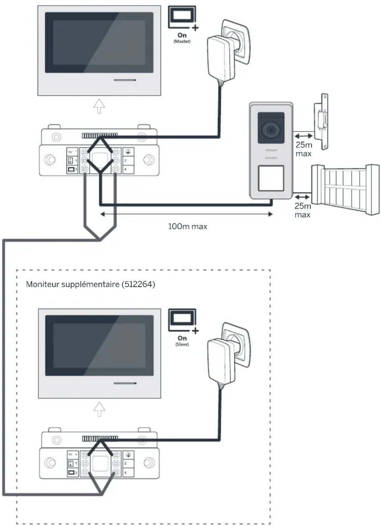
Figure 2
CONTENTS
A - SAFETY INSTRUCTIONS 07
1-OPERATING PRECAUTIONS 07
2 - MAINTENANCE AND CLEANING 07
3-RECYCLING07
B-PRODUCTDESCRIPTION08
1 - KIT CONTENTS 08
2 - GENERAL INFO 08
3-MONITOR 08
4-INTERCOM PANEL 09
5-WALLBRACKET 09
6 - MAINS ADAPTOR 09
C - INSTALLATION 10
1-WIRING 10
1.1 - Connecting the videophone (monitor, intercom panel and camera) 10
1.2 - Connecting a gate motor 10
1.3 - Connecting an electric strike plate or lock 10
2-CONFIGURATION OF THE INTERCOM PANEL 10
2.1 - Setting the volume of the intercom panel 10
2.2 - Configuration of the RFID function 10
3-INSTALLING THE SMART BRACKET 11
4 - DIAGNOSTICS AND INSTALLATION 12
5- INSTALLATION OF THE MAIN OR ADDITIONAL INTERCOM PANEL 13
D - USING THE PRODUCT 14
1 - USE OF THE VIDEO INTERCOM AND SETTINGS
E - FAQ 16
F - TECHNICAL AND LEGAL INFORMATION 18
1 - GENERAL CHARACTERISTICS 18
2 - WARRANTY 19
3- HELP AND ADVICE 19
4- PRODUCT RETURNS/ABTER-SALES SERVICE 19
5 - DECLARATION OF EC COMPLIANCE
14
19
1 - INTRODUCTION
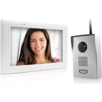
This video intercom system pairs two modules: a receiver-monitor and an easy-to-install and use intercom panel.
Key features:
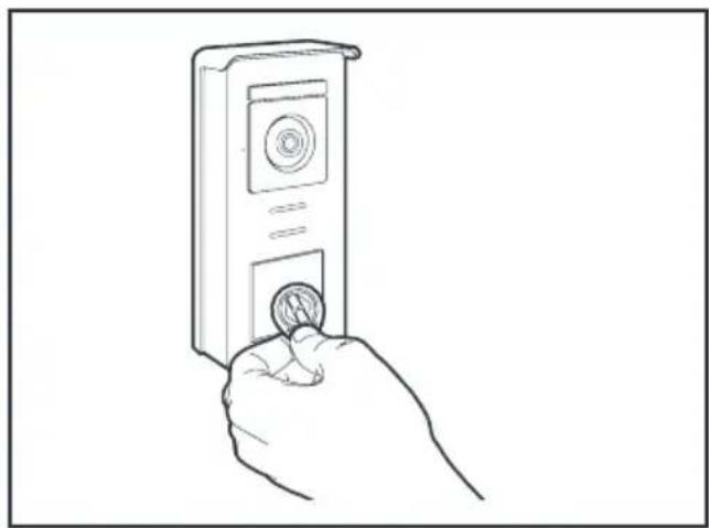
- Colour video reception: when a visitor touches the intercom panel call button, the panel immediately transmits the image to the screen and a chime indicates the visitor's presence.
- Short-circuit protection
- Reverse polarity protection
Automatic exposure correction: the video camera automatically adjusts its exposure to match the ambient light conditions. - The LEDs integrated in the intercom panel allow visitors to be identified without the need for additional lighting.
- Opening the door and a control system: by pressing buttons on the monitor, you can control an electric lock and a dry contact for an automatic control system (not included).
- Opening of the gate or the electric strike plate depends on the time it takes to read the RFID badge.
IMPORTANT: This notice should be read carefully prior to installation. In the case of any problems, our Hotline technicians are at your service to provide you with any information you may need.
WARNING: any connection error may cause damage to the device and void the warranty.
2 - MAINTENANCE AND CLEANING
Before installing your intercom, it is important to check the following points:
- Do not install in cases of extreme humidity, temperatures, corrosion risk or dust.
- Do not expose to direct sunlight, rain, or high humidity.
- Do not plug the device into a multi SOCKET plug adaptor or extension cord.
- Be careful not to lose the administrator badge (red colour) or your product will be locked and the warranty voided.
Keep it in a safe place.
A - SAFETY INSTRUCTIONS
- Do not install near other electronic devices such as computers, televisions or video recorders.
- Do not install near acidic chemicals, ammonia or sources of toxic gases.
- Do not clean with abrasive or corrosive products. Use a damp cloth with soapy water.
- Unplug the device if it is not being used for an extended period of time.
- Do not plug the device into national telecommunications installations.
- The cable between the monitor and intercom panel must not be extended. Avoid junctions (insulating screw joints, soldered joints, etc.)
3 - RECYCLING
This logo indicates that devices which are no longer in use must not be disposed of as household waste. They are likely to contain hazardous substances that are dangerous to both health and the environment.
Return the equipment to your local distributor or use the recycling collection service provided by your local council.

1 7"monitor
2 Smart" wall bracket
3 Intercom panel and protective shield
4 Plug-in power supply
5 5 RFID badges: 2 users (grey), 1 admin (yellow). 1 badge - (red), 1 badge + (blue)
2 - GENERAL INFORMATION
This videophone is composed of an interior response station with touch-sensitive buttons and an exterior panel with an intercom and camera, allowing the person inside to see and communicate with the visitor outside who rings the doorbell. The system is easy to install, with only two wires needed for all functions: the doorbell, the video feed, the intercom, and the strike plate and automated opening controls. For effective usage, please carefully read this instruction manual.
3-MONITOR
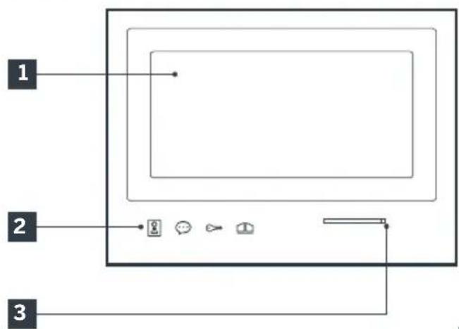
1 7" LCD screen
2 Touch-sensitive buttons
3 Microphone
4 Loudspeaker
5 Connector
6 Red: Connecting to power supply
7 Green: Connecting to intercom panel
8 Blue: Connecting to additional monitor
9 Indicator light for connecting an additional
monitor
Red = Connection error
Blue = Connection OK or monitor not present
10 Power supply indicator light
Red = Connection error
Blue = Power supply connected correctly
11 Intercom panel connection indicator light
Red = Reverse polarity
Blue = Wiring OK
12 Intercom panel connection indicator light
Red = intercom panel not connected (wire unplugged or cut)*
Blue = connection OK
- This is completely normal if the monitor is used as an additional monitor on an existing installation and no intercom panel is directly connected to it
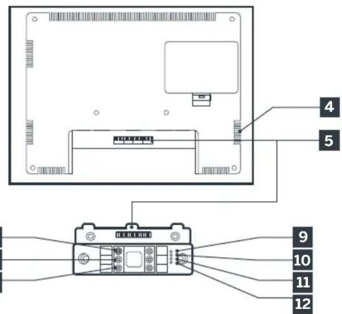
4 - INTERCOM PANEL
7
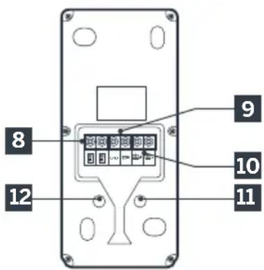
Notes:
- When the call button is pressed, the monitor rings inside and the video switches on.
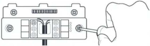
- To change the name plate label, remove the plastic protective cover on the front by sliding a small flat screwdriver into the notch provided for this purpose.
1 Twilight sensor
2 White LEDs (night vision)
3 Camera lens
4 Microphone
5 Loudspeaker
Backlit call button and RFID badge scan area
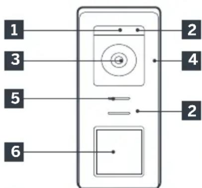
7 Tamper-resistant retaining screw
8 Connecting of the monitor
9 Connecting of the electric strike plate
10 Connecting of the dry contact (gate automation)
11 Loudspeaker volume setting (located under the rubber button)
12 RFID reset button (under the rubber plug)
5-WALL BRACKET
The monitor is designed to be fixed to the wall. A wall bracket and the necessary fasteners are included.
6 - MAINS ADAPTER
A 230 Vac 50 Hz/15 Vdc 1A mains adapter for powering the monitor is included in the kit. Do not use other power supplies as they could cause irreparable damage to the device and invalidate the warranty. Do not cut or extend the wire of the mains adapter or the warranty will be void. The 15V wire of the adapter is indicated by the presence of a red + 15V label. The ground wire of the adapter is indicated by the presence of a black ENL label.
C - INSTALLATION
Tips and important notes:
- In order to make the most of your intercom panel, we advise you to configure it (loudspeaker volume) before it is installed in its final location. To do this, you will need to connect it on a table, to ensure that the settings have been configured correctly.
- If you test your product before installing it, please do not do this with the intercom panel and the monitor in the same room, to avoid the emission of a high-pitched sound (Larsen effect).
- Do not expose the camera directly to the sun or facing a reflective surface.
- Tip: it is recommended for the wires to be covered by a sheath to protect them from bumps and the weather.
1. WIRING
To avoid the risks of interference and malfunction, do not pass the wire for your videophone through the same sheath as that housing the electrical wires (230V - 50Hz). Each cable connecting the monitor and the intercom panel must be a single part. Avoid joints (insulating screw joints, soldered joints, etc.)
Note: Do not under any circumstances double wires to increase the wire size.
1.1. Connecting the videophone (screen, intercom panel and camera, see fig. 1, fig. 2)
- Ensure proper connection of the wires, following one of the wiring diagrams depending on the desired configuration.
Take careful note of the label affixed to front of the smart device and at the back of the intercom panel.
Depending on the selected configuration, configure your monitor as a "Master" or "Slave". You can adjust this setting through the settings management menu of your monitor.
1.2. Wiring gate automation
- The intercom panel provides a dry-contact connection, without an electric current, to be connected to the control button for your automated gate.
- Connect it directly to the terminals identified on
the description of the intercom panel (Section 4 - Intercom panel) at the back of the board (no polarity to follow).
- The opening function can only be used if the respective intercom panel video is displayed.
1.3. Connecting an electric strike plate or lock
Important: The electric strike plate or lock that you install must be equipped with a mechanical memory. The power supply to the lock must not exceed 12V/1.1A.
- Connect it directly to the terminals identified on the description of the intercom panel (Section 4 - Intercom panel) at the back of the board (no polarity to follow).
- The opening function from the monitor can only be used if the respective intercom panel video is displayed.
2. CONFIGURATION OF THE INTERCOM PANEL (SEE FIG.1,FIG.2)
2.1. Intercom volume setting:
Setting the volume of the intercom and conversation volume can be done from the settings interface on the video intercom screen. More details are available in Section D - Use.
2.2. Configuration of the RFID function:
The RFID function enables opening to be managed using badges from the intercom panel, even when the screen is switched off.
2.2.1 Programming (or resetting) of administrator badges:
The first time these are activated, it is imperative for the badges to be configured in the following order:
- Press the reset button at the back of the intercom panel for 5 seconds, the intercom panel emits 6 short beeps.
- Swipe the administrator badge (yellow), a short beep confirms that it has been programmed.
-
Swipe the + badge (blue), a short beep confirms that it has been programmed.
-
Swipe the - badge (red), a long beep confirms the end of the programming of administration badges.
2.2.2 Adding one or more user badges:
- Swipe the badge - (blue), 4 long beeps confirm activation of programming mode.
- Swipe all user badges (grey) to be activated, a short beep confirms, for each badge presented, that it has been programmed.
- Once all the badges have been programmed, wait for 10 seconds. A long beep indicates the end of the programming process.
2.2.3 Deleting one or more user badges:
- Swipe the - badge (red), 4 long beeps confirm activation of programming mode.
- Swipe all user badges (grey) to deactivate, a short beep confirms, for each badge presented, that it has been cleared of any programming.
- Once all the badges have been cleared of any programming, wait for 10 seconds. A long beep indicates the end of the programming process.
2.2.4 Deleting all user badges:
- Swipe the administrator badge (yellow). 4 short beeps indicate activation of administration mode.
- Swipe 1 user badge (grey) that has been pre-added to the system, a short beep indicates that all the user badges have been cleared of any programming.
2.2.5 Use of badges:
To open the electric strike plate, quickly swipe your pre-programmed user badge (grey) over the RFID scan area. A short beep indicates the opening of the electric strike plate.
To initiate the gate motor, hold the badge in front of the RFID scanning area for 3 seconds. Two short beeps indicate that the gate is opening.
2.2.6 Replacing a badge
RFID badges do not have predefined functions. It is the programming step that sets the badge's function. Badge colours simply enable users to recognise their function. If a badge is lost, it can be replaced by any other badge by repeating the programming step.
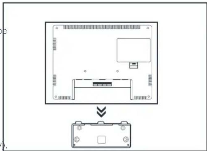
3 - INSTALLING THE INTELLIGENT BRACKET
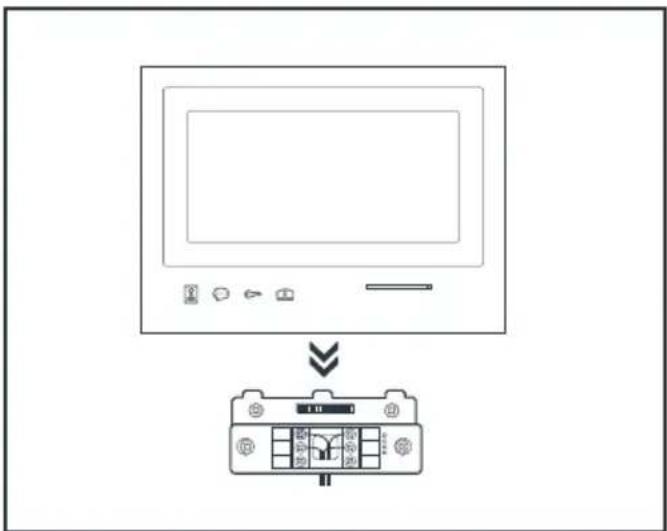
- The smart stand is magnetically attached to the back of the monitor. To gain access, please slide the support down.
- Position the bracket in the chosen location and check that it is in the optimum position for connecting the cables.
- If the cables do not emerge directly from the wall, break off the bottom plastic part.
C - INSTALLATION
1
2
3
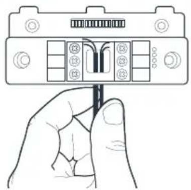
- Feed the wires into the space provided for this purpose.
- Mount the smart bracket using suitable screws and wall plugs for the type of bracket (the screws and wall plugs provided are suitable for solid walls).
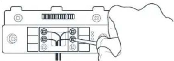
- Connect the connection terminals, ensuring you follow the colour coding accurately.
4-DIAGNOSTICS AND INSTALLATION
- Once the wiring has been completed and before installing the monitor, check the smart bracket status:
Indicator light for connecting an additional monitor
Red = Connection error
Blue = Connection OK or monitor not present
Power supply indicator light 4 :
Red = Connection error
Blue = Power supply correctly connected
Intercom panel connection indicator light 1:
Red = Reverse polarity
Blue = Wiring OK
Intercom panel connection indicator light
Red = intercom panel not connected (wire unplugged or cut)*
Blue = connection OK
-
This is completely normal if the monitor is used as an additional monitor on an existing installation and no intercom panel is directly connected to it
-
If all the indicator lights on the smart bracket are blue (with the possible exception of the one on the intercom panel, see above), place the monitor in its compartment. If not, check installation.
Warning: for this step, do not connect the 230V AC power supply.
5. INSTALLATION OF THE MAIN OR ADDITIONAL INTERCOM PANEL
Note: The product must not be connected to the power supply before the wiring has been completed.
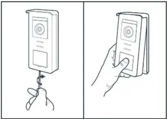
- Remove the tamper-resistant screw under the intercom panel.
- Tilt the intercom panel forwards.
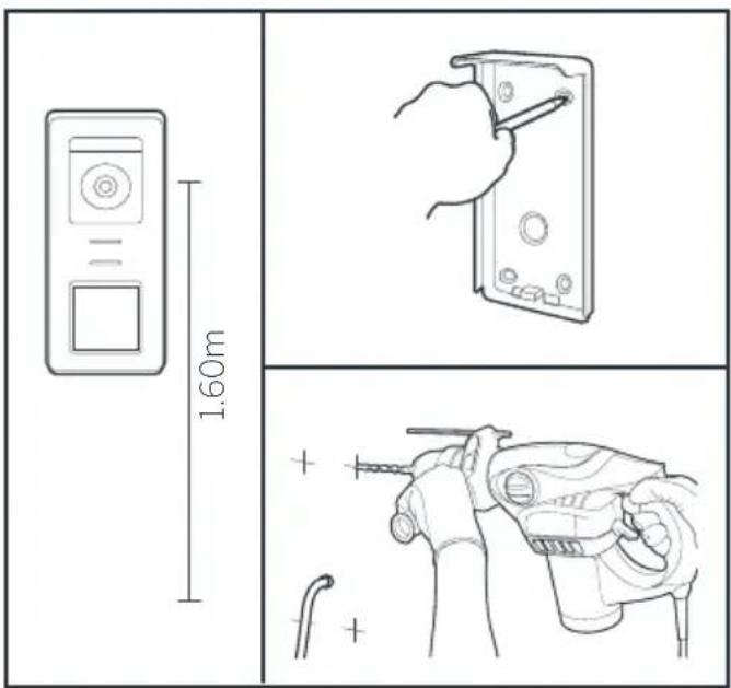
- The lens of the intercom panel must be placed at a height around 1.60m .
Make guiding marks. - Drill. Use wall plugs suitable for the nature of the material (the wall plugs provided are suitable for solid walls).
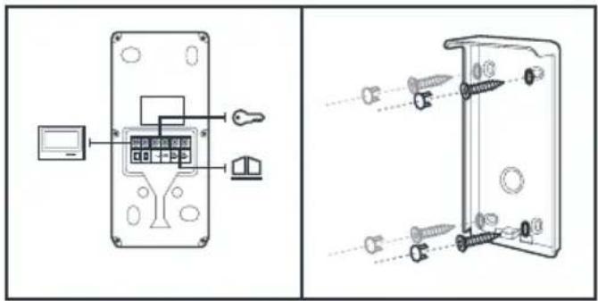
- Connect the two wires from the monitor and if necessary, connect the electric strike plate and the gate (see Section 1. Wiring).
- Check proper functioning (video call, etc.).
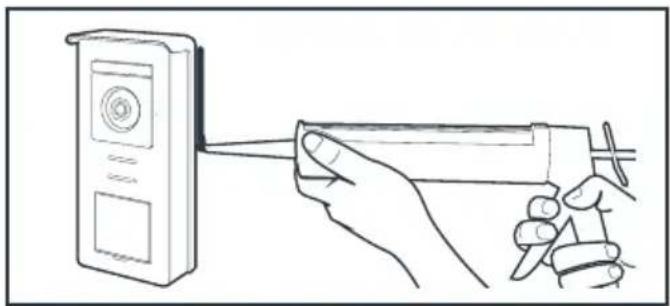
- Place a silicone* seal between the shield and the wall to avoid the infiltration of water. * Do use an acetic acid-based silicone (smells like vinegar). It is not recommended to run a silicone seal under the intercom panel
D - USING THE PRODUCT
1. USE OF THE GATE VIDEO AND SETTINGS
- The Thomson Smart Bracket II is controlled through touch-sensitive keys.
- The button functions vary depending on the menu accessed. The icons at the bottom left hand side of the screen help to guide you as to their use.
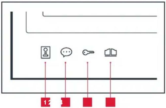
Monitor switched off: Spy mode: view intercom panel camera In the menus: navigation arrow
2 Monitor switched off: access the main menu During a call: answer the call/end the call In the menus: navigation arrow
3 Monitor switched off: access the main menu During a call: Open electric strike plate In the menus: OK/Selection
4 Monitor switched off: access the main menu During a call: Open dry contact (gate motor) In the menus: Back
WARNING: in Spy mode, the sound is not activated. You need to press on the key to start a discussion.
- Main menu
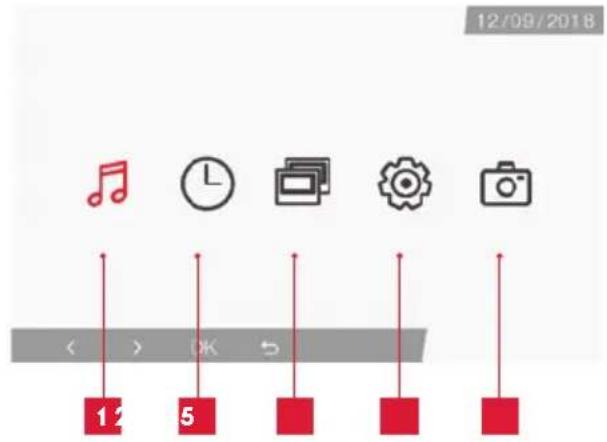
1 Doorbell melody selection and volume settings
2 Setting the date and time
3 When a second monitor is connected, select this icon and press on OK to call it
4 Adjusting the settings of your Smart Bracket II videophone
5 Management and viewing of photos captured
- Screen for doorbell melody and volume selection
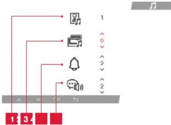
1 Doorbell melody selection (intercom panel)
2 Call volume setting (intercom)
3 Doorbell volume setting
Voice volume (intercom)
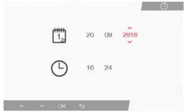
- Screen for managing date and time
- Screen for managing settings
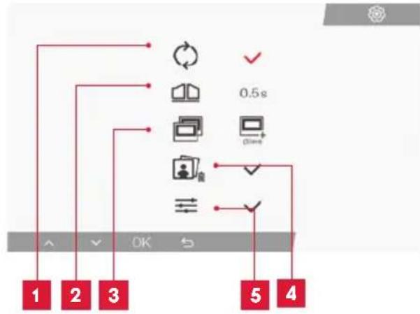
| 1 | Factory settings |
| 2 | Duration of dry contact activation for the motor |
| 3 | Monitor status ("Master" by default), only the additional monitor must be set to "Slave" |
| 4 | Erase all photos |
| 5 | Additional settings for contrast, light settings, etc. |
2. USE OF RFID BADGES
The RFID badges enable both the electric strike plates and the door controls to open. The function is selected according to how long the RFID badge is held under the scanner.
If scanned briefly, the electric strike plate opens. If held for a longer period (3 secs), the door control opens
F - FAQ
If your problem is not covered below, please contact our technical support department.
| Symptoms Possible causes Solutions | ||
| The intelligent bracket is showing an error (red light) when the screen is lit. | This is completely normal. The diagnostics run by the intelligent bracket should be relied on only when the screen is disconnected. | |
| The monitor will not switch on. | The adapter is not connected to the mains/the monitor is not inserted correctly into the intelligent bracket. | Check that all power supply cables are correctly connected. |
| No image on screen (black or blue screen). | The intercom panel and the intelligent bracket are not connected correctly. | Remove the screen of the intelligent bracket and run diagnostics. Check the connections. |
| The cable section used is not suitable for the distance between the monitor and the intercom panel. | Check the distance covered by the cable section with the help of this operating manual. | |
| The image is blurred. | The cable section used is not suitable for the distance between the monitor and the intercom panel. | Check the distance covered by the cable section with the help of this operating manual. |
| The cables that connect the intercom panel to the monitor are too close to 230V mains power cables. | If possible, use a separate duct for the cables that connect the monitor to the intercom panel. | |
| The intercom panel lens is dirty or scratched | Clean the lens of the intercom panel with a soft cloth. | |
| Background noise when talking. | The cable section used is not suitable for the distance between the monitor and the intercom panel. | Check the distance covered by the cable section with the help of this operating manual. |
| The cables that connect the intercom panel to the monitor are too close to 230V mains power cables. | If possible, use a separate duct for the cables that connect the monitor to the intercom panel. | |
| The gate control does not release the automated door. | The cable section used is not suitable. | Check the cable section with the help of this operating manual. |
| The intercom panel and the automated gate are not connected correctly. | Check the connections and input used for the automated gate with the help of the operating manual for the automated gate. | |
| The electric strike plate does not open the door. | The cable section used is not suitable. | Check the cable section with the help of this operating manual. |
| The intercom panel and the strike plate are not connected correctly. | Check the connections between the intercom panel and the electric strike plate. | |
| The style of electric strike plate used is not suitable. | Check that the strike plate is compatible with the specifications included in this manual. | |
| When speaking with a visitor, the monitor sound is low or distorted. | The intercom panel microphone is obstructed. | Check that the intercom panel microphone is clean (dirtiness, insects, etc.) |
| During a call, there is no sound or the product functions randomly | The monitor(s) is/are not in the correct "Master" or "Slave" mode | Check that the monitor is correctly configured by accessing the settings management menu |
G - TECHNICAL AND LEGAL INFORMATION
1 - GENERAL CHARACTERISTICS
| Monitor and smart bracket | ||
| Doorbells | Number 6 doorbell melo | dies to choose from (85dB) |
| Screen | Size 7 inches diagonally | (17.78cm), 16/9 |
| Resolution 800 x 480 | ||
| Picture memory capacity | 100 photos | |
| Supply voltage | 15V/1A | |
| Consumption | 400mA | |
| Temperature and humidity levels for use | -10°C to 50°C, 85% RH maximum | |
| Dimensions | 205(l)x157(h)x18(p) (mm) | |
| Intercom panel | |
| Sensor type | 1/4” CMOS |
| Viewing angle | 105° |
| Temperature and humidity levels for use | -10°C to 50°C, 85% RH maximum |
| Dimensions | 164(h)x78(l)x39(p) (mm) |
| Protection rating | IP44 |
G - TECHNICAL AND LEGAL INFORMATION
2 - WARRANTY
- This product is guaranteed for parts and labour for 3 years from the date of purchase. Proof of purchase must be retained for the duration of the warranty period.
- The warranty does not cover damage caused by negligence, knocks or accidents.
- None of the parts of this product may be opened or repaired by any persons not employed by Smarthome France.
- The warranty will be void if the device is tampered with.
3 - HELP AND SUGGESTIONS
- If, in spite of the care we have taken in designing our products and drafting these instructions, you do encounter difficulties when installing your product or you have any questions, we recommend you contact one of our specialists who will be glad to help.
- If you encounter operating problems during the installation or a few days afterwards, it is essential that you are in front of your installation when contacting us, so that one of our technicians can diagnose the source of the problem, as it will probably be the result of a setting that is incorrect or an installation that is not to specification. If the problem is caused by the product itself, the technician will give you an RMA number so that you can return the unit to the shop. Without this RMA number, the shop may refuse to exchange your product.
Contact our customer service technicians on:
0 892 701 369
Monday to Friday, 9AM to 12PM and 2PM to 6PM CET.
4 - PRODUCT RETURNS - AFTER SALES SERVICE
If, despite the care we have taken in designing
and manufacturing your product, it needs to be returned to our customer service centre, you can check the progress of the work on our website at the following address: http://sav.smart-home-france.com
Avidsen undertakes to keep a stock of spare parts for this product throughout the contractual warranty period.
5 - EC DECLARATION OF CONFORMITY
With the RED 2014/53/UE directive
Smarthome France hereby declares that the equipment designated below:
Smart Bracket II colour video intercom 512263
Complies with the RED directive and its conformity has been assessed pursuant to the applicable standards in force:
EN301489-1V2.2.0
EN 301489-3 V2.1.1
EN 300 330-1 V2.1.1
EN 300 328 V2.1.1
EN 62479: 2010
EN 62368 -1: 2014 +A11: 2017
IN Tours Alexandre Chaverot,
08/11/18 CEO

THOMSON is a TECHNICOLOR S.A. brand used under licence by:
SmartHome France
19 avenue Marcel Dassault - 37200 Tours - France
512263

De segunda a sexta-feira entre as 9h e as 12h e entre as 14h e as 18h.