
RF 14115 - Milling machine METABO - Free user manual and instructions
Find the device manual for free RF 14115 METABO in PDF.
| Brand | Metabo |
| Model | RF 14115 |
| Product type | Renovation router |
| Usage | Professional (industry and crafts) |
| Power supply | 230 V, 50 Hz (estimated) |
| Rated power input | 1600 W (estimated) |
| No-load speed | Variable, 1500 - 3000 rpm (estimated) |
| Weight (without cable) | 5.6 kg (estimated) |
| Protection class | II |
| Main applications | Removal of rendering, adhesive residues, milling formwork, concrete roughness, grinding with diamond cup wheels |
| Unsuitable applications | Cutting, coarse grinding, sanding with paper, polishing |
| Suction system | Connection for class M vacuum cleaner |
| Safety | Protective cover, spindle lock, sliding switch with lock, restart protection |
| Additional handle | Yes, angle adjustable |
| Depth adjustment | Tool-free depth stop |
| Maintenance | Cleaning with compressed air via ventilation slots |
| Repairs | By electrician or Metabo agency |
| Original accessories | Metabo (cutters, diamond cup wheels, etc.) |
Frequently Asked Questions - RF 14115 METABO
User questions about RF 14115 METABO
0 question about this device. Answer the ones you know or ask your own.
Ask a new question about this device
Download the instructions for your Milling machine in PDF format for free! Find your manual RF 14115 - METABO and take your electronic device back in hand. On this page are published all the documents necessary for the use of your device. RF 14115 by METABO.
USER MANUAL RF 14115 METABO
natural_image
Close-up of a black and white power tool with a circular base, no visible text or symbols
 | RF 14-115*1) Serial Number: 03823.. | |
| D_max | mm (in) | 115 ( 4^1/_2 ) |
| t_max1 | mm (in) | 6 ( ^1/_4 ) |
| M / I - / mm (in) | M 14 / 20 ( ^25/_32 ) | |
| n min | ^-1 (rpm) | 800 - 2800 |
| P_1 | W | 1450 |
| P_2 | W | 780 |
| m kg (lbs) | 4,3 (9.5) | |
| a_hV/K_hV | m/s ^2 | < 2,5 / 1,5 |
| L_pA/K_pA | dB(A) | 92 / 3 |
| L_WA/K_WA | dB(A) | 103 / 3 |

*2) 2004/108/EC (-> 19.04.2016) / 2014/30/EU (20.04.2016 ->), 2006/42/EC, 2011/65/EU
*3) EN 60745-1:2009+A11:2010, EN 60745-2-3:2011+A2:2013

2016-02-10, Volker Siegle
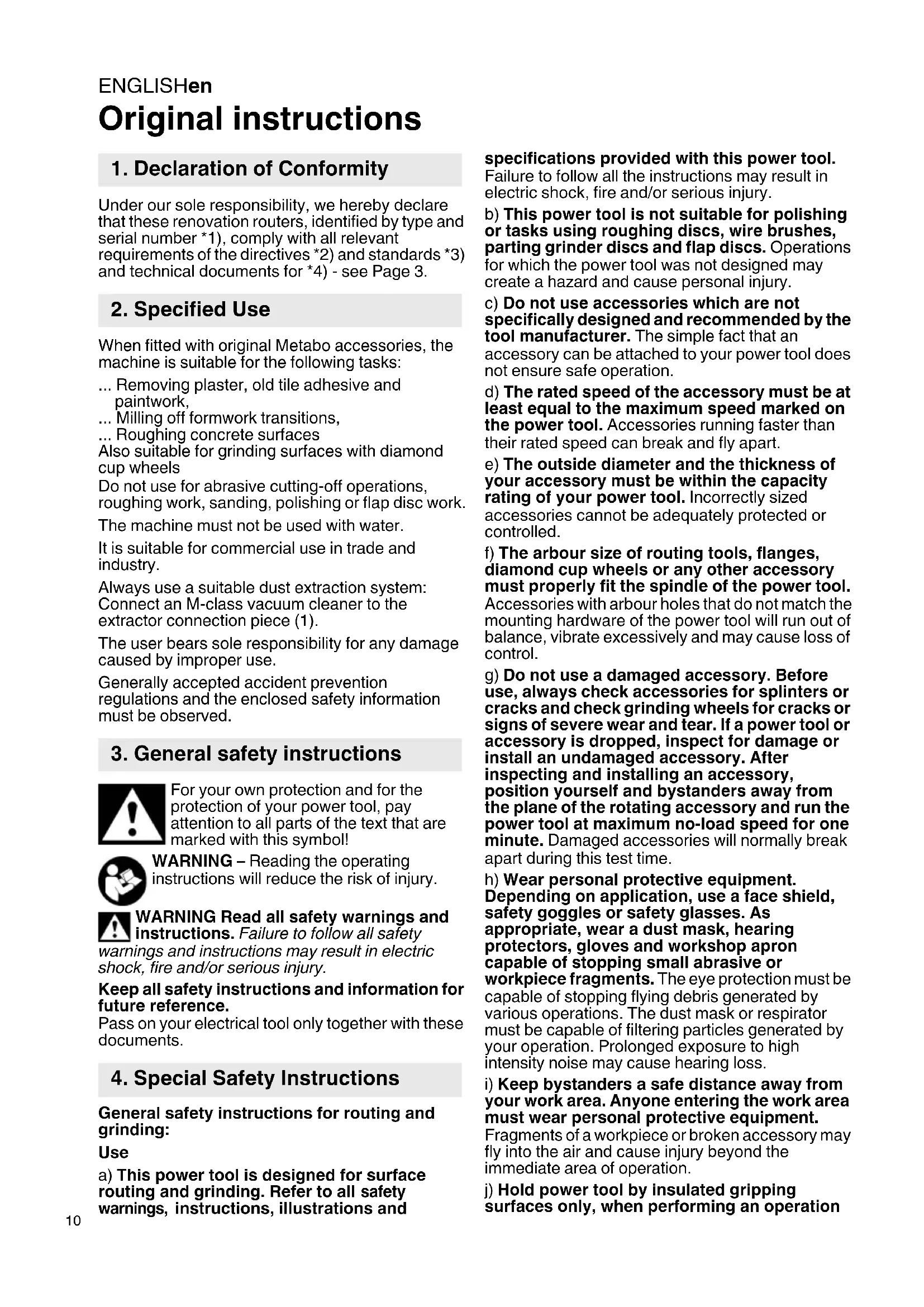
Original instructions
1. Declaration of Conformity
Under our sole responsibility, we hereby declare that these renovation routers, identified by type and serial number *1), comply with all relevant requirements of the directives *2) and standards *3) and technical documents for *4) - see Page 3.
2. Specified Use
When fitted with original Metabo accessories, the machine is suitable for the following tasks:
... Removing plaster, old tile adhesive and paintwork,
... Milling off formwork transitions,
... Roughing concrete surfaces
Also suitable for grinding surfaces with diamond cup wheels
Do not use for abrasive cutting-off operations, roughing work, sanding, polishing or flap disc work.
The machine must not be used with water.
It is suitable for commercial use in trade and industry.
Always use a suitable dust extraction system:
Connect an M-class vacuum cleaner to the extractor connection piece (1).
The user bears sole responsibility for any damage caused by improper use.
Generally accepted accident prevention regulations and the enclosed safety information must be observed.
3. General safety instructions

For your own protection and for the protection of your power tool, pay attention to all parts of the text that are marked with this symbol!

WARNING – Reading the operating instructions will reduce the risk of injury.

WARNING Read all safety warnings and instructions. Failure to follow all safety
warnings and instructions may result in electric shock, fire and/or serious injury.
Keep all safety instructions and information for future reference.
Pass on your electrical tool only together with these documents.
4. Special Safety Instructions
General safety instructions for routing and grinding:
Use
a) This power tool is designed for surface routing and grinding. Refer to all safety warnings, instructions, illustrations and
specifications provided with this power tool.
Failure to follow all the instructions may result in electric shock, fire and/or serious injury.
b) This power tool is not suitable for polishing or tasks using roughing discs, wire brushes, parting grinder discs and flap discs. Operations for which the power tool was not designed may create a hazard and cause personal injury.
c) Do not use accessories which are not specifically designed and recommended by the tool manufacturer. The simple fact that an accessory can be attached to your power tool does not ensure safe operation.
d) The rated speed of the accessory must be at least equal to the maximum speed marked on the power tool. Accessories running faster than their rated speed can break and fly apart.
e) The outside diameter and the thickness of your accessory must be within the capacity rating of your power tool. Incorrectly sized accessories cannot be adequately protected or controlled.
f) The arbour size of routing tools, flanges, diamond cup wheels or any other accessory must properly fit the spindle of the power tool. Accessories with arbour holes that do not match the mounting hardware of the power tool will run out of balance, vibrate excessively and may cause loss of control.
g) Do not use a damaged accessory. Before use, always check accessories for splinters or cracks and check grinding wheels for cracks or signs of severe wear and tear. If a power tool or accessory is dropped, inspect for damage or install an undamaged accessory. After inspecting and installing an accessory, position yourself and bystanders away from the plane of the rotating accessory and run the power tool at maximum no-load speed for one minute. Damaged accessories will normally break apart during this test time.
h) Wear personal protective equipment. Depending on application, use a face shield, safety goggles or safety glasses. As appropriate, wear a dust mask, hearing protectors, gloves and workshop apron capable of stopping small abrasive or workpiece fragments. The eye protection must be capable of stopping flying debris generated by various operations. The dust mask or respirator must be capable of filtering particles generated by your operation. Prolonged exposure to high intensity noise may cause hearing loss.
i) Keep bystanders a safe distance away from your work area. Anyone entering the work area must wear personal protective equipment. Fragments of a workpiece or broken accessory may fly into the air and cause injury beyond the immediate area of operation.
j) Hold power tool by insulated gripping surfaces only, when performing an operation
where the cutting accessory may contact hidden wiring or its own cord. A cutting accessory that comes in contact with a "live" wire may render exposed metal parts of the power tool "live" and give the operator an electric shock.
k) Position the cord clear of the spinning accessory. If you lose control, the cord may be cut or snagged and your hand or arm may be pulled into the spinning accessory.
I) Never lay the power tool down until the accessory has come to a complete stop. The spinning accessory may catch the surface and pull the power tool out of your control.
m) Do not run the power tool while carrying it at your side. Accidental contact with the spinning accessory could snag your clothing, pulling the accessory into your body.
n) Regularly clean the power tool's air vents. The motor's fan draws dust into the housing.
o) Do not operate the power tool near flammable materials. Sparks could ignite these materials.
p) Do not use accessories that require liquid coolants. Using water or other liquid coolants may result in electrocution or shock.
4.1 Kickback and Related Warnings
Kickback is a sudden reaction to a pinched or snagged routing or grinding tool or similar accessory. Pinching or snagging causes the rotating accessory to come to an abrupt halt, which in turn forces the uncontrolled power tool in the direction against the accessory's rotation at the point of jamming.
Kickback is the result of power tool misuse and/or incorrect operating procedures or conditions. It can be avoided by taking proper precautions as given below.
a) Maintain a firm grip on the power tool and position your body and arm to allow you to resist kickback forces. Always use the auxiliary handle, if provided, maximum control over kickback or torque reaction during start-up.
The operator can control torque reactions or kickback forces, if proper precautions are taken.
b) Never place your for hand near the rotating accessory. Accessory may kickback over your hand.
c) Do not position your body in the area where power tool will move if kickback occurs.
Kickback will propel the power tool in the direction against the accessory's movement at the point of jamming.
d) Use special care when working around corners, sharp edges etc. Avoid bouncing and snagging the accessory. The rotating accessory tends to jam around corners and sharp edges and also if bouncing occurs, thus causing loss of control or kickback.
e) Do not attach a saw chain woodcarving blade or toothed saw blade. Such blades create frequent kickback and loss of control.
4.2 Safety Warnings Specific for Routing Operations:
a) Use only routing tools that are recommended for your power tool and the specific guard designed for these routing tools. Routing tools that are not designed for use with the power tool cannot be guarded properly and are unsafe.
b) The guard must be securely attached to the power tool and positioned so as to minimise exposure of the routing body to the operator and thus maximise safety. The guard helps to protect the operator from broken fragments, accidental contact with the routing body and sparks that could ignite clothing.
c) Do not work on surfaces with exposed steel reinforcements or similar. Doing so may result in kickback or loss of control over the power tool.
d) Before commissioning, check that the routing wheels can move freely. Clean these, if necessary.
e) Do not use damaged routing wheels.
f) Exercise particular caution when working on corners, edges and ledges. There is a risk here of kickback or damaging the router.
g) Routing wheels have sharp edges and may be very hot after use. Caution! Risk of injury.
4.3 Safety Warnings Specific for Grinding with Diamond Cup Wheels:
a) Use only wheel types that are recommended for your power tool and the specific guard designed for the selected wheel. Wheels for which the power tool was not designed cannot be adequately guarded and are unsafe.
b) The guard must be securely attached to the power tool and positioned for maximum safety, so the least amount of wheel is exposed towards the operator. The guard helps to protect the operator from broken fragments, accidental contact with the wheel and sparks that could ignite clothing.
c) Wheels must be used only for recommended applications.
d) Always use undamaged wheel flanges that are the correct size and shape for your selected accessories. The correct flanges support the accessories.
4.4 Additional Safety Instructions

WARNING – Always wear protective goggles.

Wear a suitable dust protection mask.
Observe the specifications of the accessory manufacturer! Protect the accessories from grease and physical impact.
Accessories must be stored and handled with care in accordance with the manufacturer's instructions.
ENGLISHen
The workpiece must lay flat and be secured against slipping, e.g. using clamps. Large workpieces must be supported adequately.
If accessories with threaded inserts are used, the end of the spindle may not touch the base of the hole on the grinding tool. Make sure that the thread in the accessory is long enough to accommodate the full length of the spindle. The thread in the accessory must match the thread on the spindle. See page 3 and chapter 15. Technical Specifications for more information on the spindle length and thread.
Impurities that manage to enter the machine may block the switching
mechanism. This is why, when the machine is running, it is necessary to blow compressed air through the rear ventilation slots of the machine regularly, frequently and thoroughly. The machine must be held firmly in this case.
Dust from material such as paint containing lead, some wood species, minerals and metal may be harmful. Contact with or inhalation of the dust may cause allergic reactions and/or respiratory diseases to the operator or bystanders.
Certain kinds of dust are classified as carcinogenic, such as oak and beech dust, especially in conjunction with additives for wood conditioning (chromate, wood preservative). Material containing asbestos must only be treated by specialists.
- For efficient dust collection, use a suitable Metabo M-class vacuum cleaner together with this power tool.
- The work place must be well ventilated.
- The use of a dust mask of filter class P2 is recommended.
Follow national requirements for the materials you want to work with.
Materials emitting dusts or vapours that may be harmful to health (e.g. asbestos) must not be processed.
When working in dusty conditions, ensure that ventilation openings are not blocked. If it becomes necessary to remove dust, first disconnect the power tool from the mains supply (use non-metallic objects) and avoid damaging internal components.
Damaged, eccentric or vibrating tools must not be used.
Avoid damage to gas or water pipes, electrical cables and load-bearing walls (static).
Connect a FI circuit-breaker with max. release current (30 mA) upstream when using the machine outdoors!
Pull the plug out of the socket before making any adjustments, converting or servicing the machine.
A damaged or cracked additional handle must be replaced. Never operate a machine with a defective additional handle.
A damaged or cracked safety guard must be replaced. Never operate a machine with a defective safety guard.
5. Overview
See page 2.
1 Extractor connection piece
2 Threaded holes on gear housing (both sides)
3 Thumbs screws
4 Additional handle
5 Locking discs
6 2 - h o l e s p a n n e r
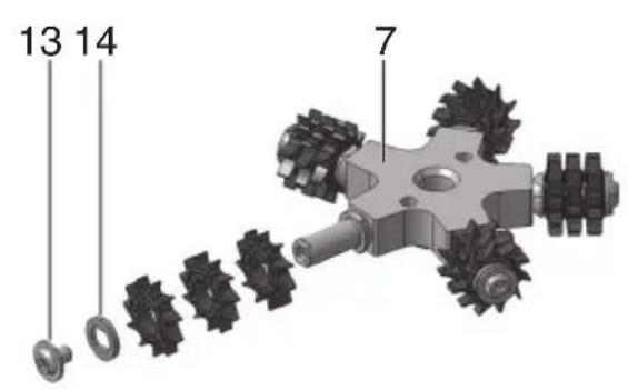
7 Routing tool*
8 Spindle
9 Spindle locking button
10 Clamping nut *
11 Diamond cup wheel*
12 Support flange *
13 Screw *
14 Safety disc*
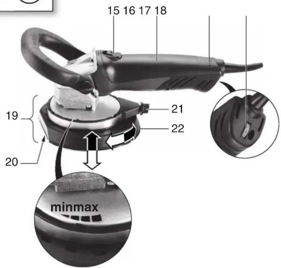
15 Sliding on/off switch
16 Handle
17 Electronic signal indicator
18 Speed adjustment wheel
19 Safety guard
20 Flat area for working close to edges
21 Wing nut
22 Depth stop
* depending on equipment/not in scope of delivery
6. Initial Operation
Before plugging in the device, check that the rated mains voltage and mains frequency, as specified on the rating label, match your power supply.
Australia: Always use a residual current device (RCD) protected supply with a rated residual current of 30 mA or less.
6.1 Attaching the additional handle
Always work with the additional handle attached (4)! Attach the auxiliary handle as shown.
See illustration A on page 2.
- Fit locking discs (5) to the left and right of the gear housing.
- Fit the additional handle (4) on the gear housing.
- Insert the thumb screws (3) to the left and right of the additional handle (4) and turn gently.
- Adjust the additional handle to the required angle (4).
- Manually tighten the thumb screws (3) to the left and right.
6.2 Adjusting the depth stop
For safety reasons, only use the safety guard (19) provided.
See figure, page 2.
- Release wing screw (21).
- Twist the depth stop (22) to adjust the height in relation to the accessory and the work task.
- Hand-tighten the wing screw (21) securely.
6.3 Dust extraction

Always use a suitable dust extraction system: Connect an M-class vacuum cleaner to the actor connection piece (1).
7. Attaching the accessory

Disconnect the mains plug before changing any accessories. The machine must be shed off and the spindle must be at a standstill.
7.1 Locking the spindle

Press in the spindle locking knob (9) only when the spindle is stationary!
- Press in the spindle locking button (9) and turn the spindle (8) by hand until you feel the spindle locking button engage.
7.2 Fitting/removing the routing tool

For safety reasons, use the safety guard (19) with the attached depth stop (22).
See illustration B on page 2.
To fit:
- Lock the spindle (see chapter 7.1).
- Screw on and tighten the routing tool (7) using the 2-hole spanner (6) in a clockwise direction.
To remove:
- Lock the spindle (see chapter 7.1). Unscrew the routing tool (7) with the 2-hole spanner (6) in an anticlockwise direction.
7.3 Fitting/removing the diamond cup wheel

For safety reasons, use the safety guard (19) with the attached depth stop (22).
See illustration C on page 2.
To fit:
- Fit the support flange (12) on the spindle. (8) The flange should not turn on the spindle when properly attached.
- Lay the diamond cup wheel (11) on the support flange (12) so that it lies flat along the support flange.
- The 2 sides of the clamping nut (10) are different. Screw the clamping nut onto the spindle so that the band of the clamping nut (10) is facing upward.
- Lock the spindle (see chapter 7.1). Turn the clamping nut (10) clockwise using the 2-hole spanner (6) to secure.
To remove:
- Lock the spindle (see chapter 7.1). Turn the clamping nut (10) anticlockwise using the 2-hole spanner (6) to unscrew.
8. Use
8.1 Setting speed
Set the optimum speed on the setting wheel (18), depending on the application.
8.2 Switching On and Off

Always guide the machine with both hands.

Switch on first, then guide the accessory towards the workpiece.

The machine must not be allowed to draw in additional dust and shavings. When switching machine on and off, keep it away from dust sits. After switching off the machine, only place own when the motor has come to a standstill.

Avoid inadvertent starts: always switch the tool off when the plug is removed from the socket or if there has been a power cut.

In continuous operation, the machine continues running if it is forced out of your ls. Therefore, always hold the machine with hands using the handles provided, stand in a position and concentrate.
Machines with slide switch:

Switching on: Push the slide switch (15) forward. For continuous activation, now tilt downwards until it engages.
Switching off: Press the rear end of the slide switch (15) and release.
9. Maintenance
Replace worn or damaged routing wheels (see figure, page 2):
- Removing the routing tool (see chapter 7.2).
- Extract the screw (13) in an anticlockwise direction. Remove the safety disc (14).
- Replace all routing wheels as shown.

(Always use the same type of routing wheels). -Reassemble all parts as shown.

Insert and turn the screw (13) in a clockwise direction and tighten with 7 Nm ± 1 Nm.
10. Cleaning
Motor cleaning: blow compressed air through the rear ventilation slots of the machine regularly, frequently and thoroughly. The machine must be held firmly in this case.
11. Troubleshooting

The electronic signal display (17) lights up and the load speed decreases. The coil temperature is too high! Run the machine in idling until the electronics signal indicator switches off.

The electronic signal display (17) flashes and the machine does not start. The restart protection is active. If the mains plug is inserted with the machine switched on, or if the current supply is restored following an interruption, the machine does not start up. Switch the machine off and on again.
ENGLISHen
12. Accessories
Use only genuine Metabo accessories.
Use only accessories that fulfil the requirements and specifications listed in these operating instructions.
For a complete range of accessories, see www.metabo.com or the catalogue.
13. Repairs

Repairs to electrical tools must be carried out by qualified electricians ONLY!
If you have Metabo electrical tools that require repairs, please contact your Metabo service centre. For addresses see www.metabo.com.
You can download spare parts lists from www.metabo.com.
14. Environmental Protection
The sanding dust generated may contain hazardous materials: do not dispose of with the household waste, but at a special collection point for hazardous waste.
Observe national regulations on environmentally compatible disposal and on the recycling of disused machines, packaging and accessories.

To protect the environment, do not dispose of power tools with household waste. Observe national regulations on separated collection recycling of disused machines, packaging and sories.
15. Technical specifications
Explanation of details on page 3. Subject to change in line with technical advances.
$$ \begin{array}{r l} D _ {\max} & = \text { max. diameter of accessory } \ t _ {\max, 1} & = \text { Max. permitted thickness of clamping } \ & \text { shank on accessory when using } \ & \text { clamping nut (10) } \end{array} $$
$$ M = S ^ {\prime} p i n d l e t h r e a d $$
I = Length of the grinding spindle
n^* = No-load speed (maximum speed)
P_1 = Nominal power input
P_2 = Power output
m = Weight without mains cable
Measured values determined in conformity with EN 60745.
□ Machine in protection class II
\~ Alternating current
* Energy-rich, high-frequency interference can cause fluctuations in speed. However, the fluctuations disappear as soon as the interference fades away.
The technical specifications quoted are subject to tolerances (in compliance with the relevant valid standards).

Emission values
Using these values, you can estimate the emissions from this power tool and compare these with the values emitted by other power tools. The actual values may be higher or lower, depending on the particular application and the condition of the tool or power tool. In estimating the values, you should also include work breaks and periods of low use. Based on the estimated emission values, specify protective measures for the user - for example, any organisational steps that must be put in place.
Vibration total value (vector sum of three directions) determined in accordance with EN 60745:
$$ \begin{array}{r l} {a _ {\mathrm{hV}}} & {= \text { Vibration emission level }} \ & {\quad (\text { grinding })} \end{array} $$
$$ K _ {h, \dots} = \text { Uncertainty (vibration) } $$
Typical A-effective perceived sound levels::
$$ L _ {p A} = \text { S o u n d p r e s s u r e l e v e l } $$
$$ L _ {W A} = \text { Acoustic power level } $$
$$ K _ {p A}, K _ {W A} = \text { Uncertainty } $$
During operation the noise level can exceed 80 dB(A).

Wear ear protectors!
K_n, = incertitude (vibration)
$$ K _ {p A}, K _ {W A} = \text {onzekerheid} $$
5 D is c o d i a r r e s t o
6 Chiave a due fori
8.1 Stille inn turtall
a_hV = Vibrationsemission (slibning)
K_h, = Usikkerhed (vibration)


- Original instructions
- Declaration of Conformity
- Specified Use
- General safety instructions
- Special Safety Instructions
- Kickback and Related Warnings
- Safety Warnings Specific for Routing Operations:
- Safety Warnings Specific for Grinding with Diamond Cup Wheels:
- Additional Safety Instructions
- ENGLISHen
- Overview
- Initial Operation
- Attaching the additional handle
- Adjusting the depth stop
- Dust extraction
- Attaching the accessory
- Locking the spindle
- Fitting/removing the routing tool
- To fit:
- To remove:
- Fitting/removing the diamond cup wheel
- Use
- Setting speed
- Switching On and Off
- Machines with slide switch:
- Maintenance
- Cleaning
- Troubleshooting
- Accessories
- Repairs
- Environmental Protection
- Technical specifications
- Emission values
- Wear ear protectors!
- Stille inn turtall
Brand : METABO
Model : RF 14115
Category : Milling machine